Abstract
Acoustics is an important factor in mosque prayer halls that had not been given extensive concern during the architectural design stages. Eventually, the importance of speech intelligibility became more important, given the integration of other activities into the prayer halls, such as the holy Quran recitation, speeches, and lectures. Early attempts have been made to control the propagation of sound and to maintain good acoustic quality within the prayer spaces. Architects during the conceptual design stage had barely paid attention to the design issues that affect the acoustic environment inside the prayer zones, which is either due to lack of time during the project development or, in most cases, a lack of simple design guidelines to overcome any drastic acoustical defects arising from the incorrect design, shape, or material selection. The basic guidelines for designers to select the appropriate shape, geometry, size, and finishing materials are an essential design tool. This work examines the three common design topologies of mosques, which differ in size, shape, and finishing materials. In this study, a geometric and material parametric analysis was conducted based on the shape, surface area, volume, and finishing materials of each of the three designs. For the geometric acoustics, a computer model employing the ray tracing theory was employed to investigate the three configurations. Different acoustic treatments were tested relative to the geometric disposition of each design. Finally, basic recommendations and design guidelines were presented.
Keywords
Acoustics ; Mosques ; Sound propagation ; Acoustic computer simulation
1. Introduction
Since Sinan (Mutbul Kayili, 2005 ) drew significant attention to the acoustics of mosque design, mosques have been considered multi-use architectural indoor spaces where various activities are performed. Several activities take place inside the mosque in separate or connected order. The primary activity is the performing prayers led by the Imam (Khateeb and Ismail, 2007 ). Another activity is a preaching speech, which may be delivered in an individual lecture or in conjunction with the weekly Friday prayers. An additional activity is the recitation of some of the verses of the holy Quran. Thus, the quality of the acoustic environment is important in the conduct of these multidisciplinary activities in the mosque.
Based on the prayer hall functions inside the mosque, acoustics should be the greatest determinant of the architectural design strategy (Hammad, 1990 ). The acoustical environment in the mosque is expressed in terms of its reverberation time (RT) value. Most contemporary mosque designers do not pay attention to such requirements during the conceptual design stage. Based on the prayer function, wherein the worshippers are ordered in subsequent rows, most of the mosques are generally rectangular with high length-to-width ratios and relatively elevated ceilings. A previous work (Abdou, 2003 ) examining different mosque shapes showed that the rectangular mosques exhibited better spatial distribution for acoustical quality indicators than other shapes. In addition, all mosque designs include a Mihrab (prayer niche) and Minbar (preacher platform). Most of the mosques also have a hemispherical dome constructed on the roof level as part of the basic design topology. Such geometrical characteristics were examined using computer modeling to study the various impacts of mosque size and form on the acoustic spatial distribution.
2. Contemporary mosque design
Nowadays, most contemporary mosques have sound-reflecting materials on most of its internal surfaces, except at the floor level and on horizontal surfaces that are usually laid out with carpet. Doors are constructed from wood, and large windows are probably filled with single glazing. The positioning of the central chiller units or stand-alone split units inside designated spaces or on roof tops amplifies the background noise levels inside the prayer areas, and affects the acoustic spatial tranquility of the space.
The Mihrab was initially designed to point towards the direction of Mecca and to give the Imam space to lead all worshippers who stand in rows behind him during prayers (Khateeb and Ismail, 2007 ). The circular shape and quarter spherical top of the Mihrab was geometrically developed to improve the reflected sound component towards the worshipper’s direction. However, in some contemporary architectural designs, the Mihrab was altered in size and shape without any attention to its acoustical implications.
The mosque plan, the conventional rectangular shape, and the large prayer halls are similar and have a common design topology that is still tied to the past. The rectangular prayer halls have better acoustical quality and performance than other shapes (Abdou, 2003 ). The advance in public address system technology and the use of loudspeakers offers the architect flexibility to shape up the prayer space according to his conceptual criteria. However, the rectangular shape is still applied in the modern design of mosques because of its historical significance. In old designs, the high ceiling, domes, and large windows allowed natural ventilation, acted as a passive environmental control, and provided day lighting. Furthermore, arches and domes were used as main structural elements to cover larger spans. With the advance in artificial air-conditioning and ventilation, natural ventilation is less of a determining factor in modern mosque designs. Moreover, daylight became less important after the development of artificial lighting technologies.
3. Mosque geometric parameters
The purpose of this work is to identify some of the common factors and differences in the acoustics of mosques of different sizes. The acoustic data and information about the mosques were obtained from architectural design data, as well as the material schedules, offered by the mosque designers, considering real case scenarios. The goals of this research are:
- To characterize mosques according to main acoustical and architectural features.
- To compare the acoustical behavior of mosques of different sizes and shapes.
The acoustic and architectural parameters implemented in this work were based on the selection of three different-sized prayer halls. Two of the prayer halls selected are located in the Dewela Mosque in Kuwait. The third prayer hall selected is the Damascus City Centre Mosque, Mudun Cities of Arabia Project. The mosque geometrical data are presented in Table 1 .
| Dewela Mosque main prayer hall | Dewela Mosque daily prayer | Damascus City Centre Mosque | |
|---|---|---|---|
| Area | 11204.913 m2 | 2372.343 m2 | 1458 m2 |
| Effective volume | 186369.000 m3 | 20689.637 m3 | 9556.322 m3 |
| Max. length | 138.80 m | 113.91 m | 69.2 m |
| Max. width | 82.00 m | 21.44 m | 21.2 m |
| Max. height | 48.00 m | 8.40 m | 23.6 m |
| Min. height | 16.70 m | 7.00 m | 5.95 |
| Total effective surface area | 27047.330 m2 | 7002.034 m2 | 4106.869 m2 |
The set of prayer halls examined presented the main design topologies related to the historical roots of mosque design. As shown in Fig. 1 , the Dewela Mosque main prayer hall represents a big enclosed prayer space and crowned at the centre by a big hemispherical dome, which is a typical design of many old historical Ottoman period mosques such as the Suleymaniya and Selimiye Mosques in Istanbul (Mutbul Kayili, 2005 ). The daily prayer hall in the Dewela Mosque represents an extended rectangular space that is relatively smaller than the main prayer hall with a flat roof and ornaments. The Damascus City Centre Mosque represents an internal pitched roof prayer hall (Rowaq), which is lifted on an array of internal vertical columns and covered centrally by a lifted dome. The Damascus City Centre Mosque contains an open prayer zone (Sahn). However, this part was excluded in the simulation, and only the enclosed iwan was simulated.
|
|
|
Fig. 1. Relative scales of the three mosques. |
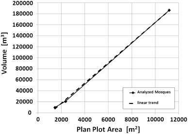
The selection criteria were set to maintain various cross relationship geometrical parameters with increasing mosque size, as shown in Fig. 1 . The relationship of the mosque plot area and volume is shown in Fig. 2 . Evidently, the linear relationship demonstrated by the graph proves that the selected mosques maintain a linear volume and plot area relationship. The volume increases with increasing plot area. The linear relationship should ensure a linear increase in RT with the increase in volume, and any deviation is due to the effect of the geometrical disposition of each mosque and its design aspects if the finishing materials are of similar absorption characteristics.
|
|
|
Fig. 2. Volume plot area relationship. |
The linear increase in volume with increasing surface area is represented in Fig. 3 . The relative data are represented in terms of its relationship to the plot area of the mosque prayer hall. The steady relationship between the effective surface areas relative to the surface area of the plan is shown by the solid circle lines. However, the resultant volume from the integration of these surface areas resulted in a relative increase in the effective volume to plan the surface area ratio for some geometries. This result is most probably due to the presence of the dominant hemispherical domes in the main prayer and daily prayer halls of the Dewela Mosque.
|
|
|
Fig. 3. Prayer halls geometrical parameters relationship. |
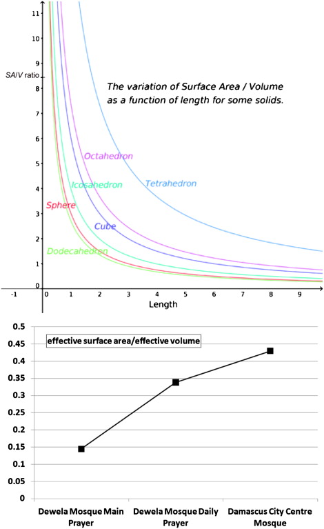
The ratio of the effective surface area to the effective volume for the three prayer halls is plotted in Fig. 4 . The effect of the large hemispherical domes in reducing the surface area is represented by the solid square plots. The upper curves in Fig. 4 clearly show the low surface area/volume (SA/V) ratio of the sphere compared with the other geometrical shapes.
|
|
|
Fig. 4. SA/V ratio. |
The SA/V ratio for a unit volume of a sphere is 4.836. By contrast, the SA/V ratio of a cube is 6 ( Schmidt-Nielsen, 1984 ; Vogel, 1988 ). Thus, using geometrical shapes that are similar to the curved surface of a sphere, such as icosahedrons and dodecahedrons, reduces the SA/V ratio.
4. Characteristics of the architectural finishing materials of mosques
The acoustical behavior, impact of acoustical material, and perception of sound inside the mosque prayer halls are rarely considered during the conceptual design stage. Although acoustics is an important factor due to the importance of speech intelligibility in such spaces, the selection of materials is always subject to other design factors of architectural and visual impacts.
In most contemporary mosques, the walls and ceilings are probably constructed of hard reflective materials because of the ease of maintenance and hygienic issues. A common material used in walls because of its luxurious and rich visual characteristics is marble. The hand-crafted ornaments in marble have been replaced in present-day mosques with GRC because of its mass production potential and ease of construction. In most cases, the materials selected for walls and ceilings are made of hard reflective materials. The floor is commonly laid with carpet. The high acoustic absorption characteristics of the carpet regulate the effect of creating a highly reverberant space, if installed above the underlay. A list of common finishing materials used in contemporary mosques and the three halls examined in this work is shown in Table 2 .
| Place | Height | Size | Mounting | Remarks |
|---|---|---|---|---|
| Summarized list of common finishing materials | ||||
| 1. Walls | ||||
| Marble Panels, on plastered masonry Brickwork | +1.5 m F.F.L. | As per drawings | Mechanical If above +4.5 F.F.L | Columns, Mihrab, side walls |
| Single Glazed window panels | ATD | As per drawings | Wall embedded | – |
| Paint on 1.5–2.0 cm cement plaster | ATD | As per drawings | Wall partition | – |
| Walls [plastered Brick work] | ATD | As per drawings | Masonry Wall partition | – |
| Granite Panels, on plastered masonry Brickwork | ATD | As per drawings | mechanical | Columns, Mihrab, side walls |
| 1.1 Parapet, windows sills and cross beams | ||||
| Single Glazed window screen | ATD | As per drawings | Wall embedded | – |
| Paint on 1.5–2.0 cm cement plaster | ATD | As per drawings | Wall partition | – |
| 2. Ceiling | ||||
| Gypsum Boards | ATD | Ceiling embedded | As per drawings | – |
| Paint | ATD | Ceiling embedded | As per drawings | – |
| GRC | ATD | Ceiling embedded | As per drawings | – |
| 2.1 Ironmongery, and Handrails | ||||
| Metal | - | As per drawings | As per drawings | – |
| 3. Floors | ||||
| Carpet | – | As per architectural design | As per architectural design | Most of the floor |
| Carpet Underlay | – | As per drawings | As per drawings | Under carpet |
| Wooden floor | – | As per architectural design | As per architectural design | – |
| 4. Windows | – | – | Single glazed windows | |
| 5. Doors | Doors | – | ||
ATD— according to design.
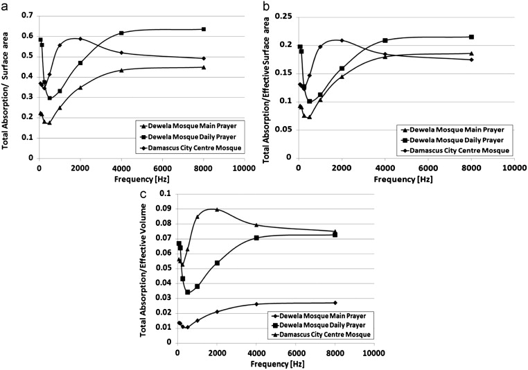
The analysis of the relative relationship of the geometrical parameters and selected material characteristics is shown in Fig. 5 for each octave band frequency. The equal trends shown by curves a and b also reflect the linear increase in volume with increasing surface area. The curves reflect an increase of 2.5 times of an order in the main and daily prayer halls of the Dewela Mosque and 2 times in the Damascus City Centre Mosque ( Fig. 3 ).
|
|
|
Fig. 5. Architecture finishing materials characteristics. (a) Total absorption/surface area, (b) total absorption/effective surface area, (c) total absorption/effective volume. |
The results show the common absorption characteristics in the three prayer halls examined.
The SA/V ratio effect is also shown in Fig. 5 c, with the presence of curved surfaces, such as the hemispherical domes, in the main and daily prayer halls of the Dewela Mosque and the rectangular shaped abstract form of the Damascus City Centre Mosque. Plotting the absorption characteristics relative to volume, resulted in lower values for the Damascus City Centre Mosque prayer hall because of its low SA/V ratio.
5. The computer model simulation
Given the nature and complexity of the interior geometry of the three prayer halls examined, implementing a feasible computer model theory is important to obtain good quality data. The examined halls are large architectural spaces. Thus, aside from the near field effect, the far field contribution is important to model in the three-dimensional space. Simplified and two-dimensional approaches (Clayden et al ., 1975 ; Holmes and Lyon, 1974 ) are not suitable.
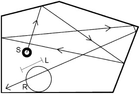
Thus, in this work, the ray tracing model was implemented during the computer predictions. The ray tracing technique (Heutschi, 1995 ) is based on following the reflections on the surface areas of each ray emitted from the source location (Fig. 6 ) as it undergoes reflections and diffraction at building surfaces until the order of the reflection of the rays exceeds a specified amount. The intensity at a point due to direct sound is calculated using the inverse square law. The numbers of rays generated in each run must be large enough to acquire quality data. The generation is repeated several times and usually more than 100,000 rays are used. The ray tracing approach (Heutschi, 1995 ) has proven to be very accurate and reliable, as long as a sufficient number of rays are used. The number of rays is easily verified for each space and volume individually by increasing the number of rays in packets of 500 until a convergence criterion is reached.
|
|
|
Fig. 6. Ray tracing analysis. |
6. RT evaluation
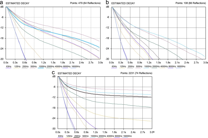
Once the source position was determined, the software generated the number of rays required, which interacted with the modeled surface reflections, to obtain an estimated RT. The rays continued to lose energy with increasing reflection order until it attenuated to a certain quantity (e.g., 40–60 dB). At this point, the rays were considered completely absorbed and contributed no more energy to the resultant sound field. The collective behavior was resumed in the estimation of the RT for each frequency. The resultant decay curves for the three examined prayer halls are shown in Fig. 7 , which presents the geometrical features of the three prayer halls and the absorption coefficients of materials.
|
|
|
Fig. 7. Decay curves before acoustic treatment. (a) Dewela Mosque main prayer, (b) Dewela Mosque daily prayer hall, (c) Damascus City Centre Mosque. |
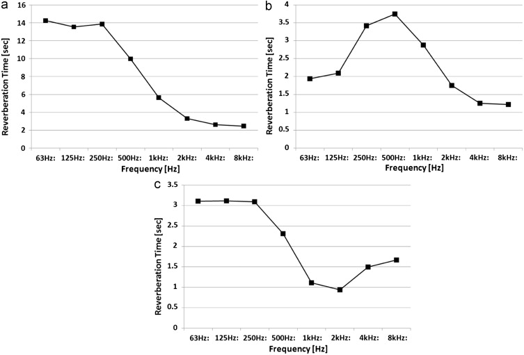
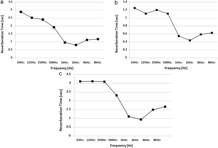
The RT values extracted from the decay curves are shown in Fig. 8 .
|
|
|
Fig. 8. Reverberation time before acoustic treatment. (a) Dewela Mosque main prayer, (b) Dewela Mosque daily prayer hall, (c) Damascus City Centre Mosque. |
The predicted RT values exceeded the optimum values. Previous studies (Marsilio et al ., 2001 ; Karabiber, 2000 ) show that the values of RT are high, providing the room with a preferred feeling of majesty and confers a holy atmosphere among the worshippers. The prayer halls are generally poorly suited for delivering speeches because of the excess reverberation, although the situation seems somehow compensated by the additional absorption contributed by the floor area. These provide better speech communication that can be established in the short range. This treatment and the addition of some acoustic treatments to the internal building fabric regulate the RT.
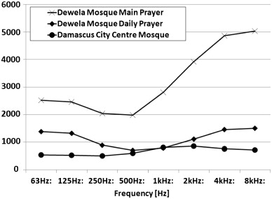
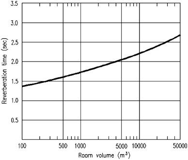
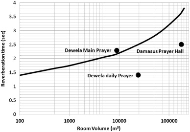
The results of the reverberation time shown in Fig. 8 are clearly inversely proportional to the total absorption shown in Fig. 9 . The high absorption rates obtained at high frequency ranges in the main prayer hall of the Dewela Mosque are due to the large surface area of the gypsum ornaments of the dome and the dome cylindrical supporting neck. This phenomenon was also observed in the Damascus City Centre Mosque, and supports the previous finding, given that these two types of prayer halls have hemispherical domes constructed in the ceiling. Thus, providing additional absorption for this large surface area of hemispherical geometry at mid- and low-frequency ranges is important. On the other hand, at the Dewela Mosque, the prayer hall needs additional absorption at mid-frequency ranges. The RT values predicted were compared with the preferred values suggested in previous literature (Sinan Eserlerinde Akustik, 1989 ; Everest, 1994 ), as shown in Fig. 10 . These studies reported plots of RT values versus room volume for different purposes. The values of the three prayer halls were not suitable for the purpose of prayer, and the RT values were too high to ensure good speech intelligibility.
|
|
|
Fig. 9. Total absorption. |
|
|
|
Fig. 10. Recommended reverberation time RT for mosques. |
7. Acoustic treatment
The results for the predicted RT values require the need for an acoustical corrective design for the three prayer halls. The data analysis revealed high RT values, especially for mid- and low frequencies. This configuration is not suitable for the intelligibility and perception of speech in prayer environments. Thus, the acoustic treatment proposed aims to reduce the RT. The ideal behavior of sound rays in the prayer halls was modeled using the Autodesk© Ecotect software (Square One, 2004 ) in the previous stage and acoustic treatment evaluation stage. This software is a building design and environmental analysis tool that simulates and analyzes the acoustical response of a building. Moreover, this tool allows designers to work with three dimensions and furnish an impressive presentation of the final design and acoustical behavior of the architectural space under analysis. The actual geometry of the three prayer halls was fully modeled using the Ecotect software framework. The first step was drawing the project geometrically. The acoustic characteristics of the different construction materials were considered, which is very critical to the purpose of modeling sound absorption. The simulation of the source was performed by assuming an isotropic source placed at the center of the hall near the Minbar. Different analyses were then performed, such as RT evaluation, reflection analysis, and materials analysis, among others.
As outlined previously, the Dewela Mosque main prayer hall and the Damascus City Centre Mosque require more absorption applied to the hemispherical dome surface area at low- and mid frequencies. The dome form is one of the most inconvenient forms in acoustics design because of the concave curvatures. The propagating sound energy does not escape without reflecting several times inside the dome shell. Given this effect, the reflected sound energy from the dome returns to the main space with a time delay, resulting in echoes or noise in the main prayer hall and the reduction in the percentage of intelligibility. The reflected sound energy that is increasingly delayed, especially in large domes, is the cause of echoes.
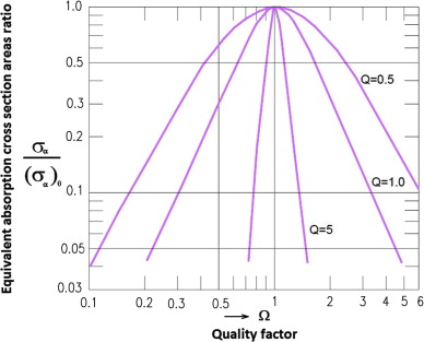
The traditional solution implemented during the Ottoman period (Mutbul Kayili, 2005 ) is the installation of cavity resonators inside the dome structure. Helmholtz resonators, or cavity resonators, built inside the dome absorb a considerable amount of sound energy and reradiate the residual sound throughout the main hall. By diffusing the incident sound energy in all directions, the room becomes a diffuse sound field, preventing dangerous echoes due to the delayed reflections from the dome shell. Aside from creating a diffused field, the sound energy directly reflected from the dome, creates a divine atmosphere of worship. This application became a tradition in Ottoman architecture. The cavity resonator system absorbs a narrow frequency band with the frequency concentrated at the site where resonance frequency occurs. By decreasing the system quality factor (i.e., by increasing the interior resistance and volume), widening the absorption frequency band to a certain degree is possible (Mutbul Kayili, 2005 ), as shown in Fig. 11 .
|
|
|
Fig. 11. Equivalent absorption cross section areas ratio of resonators vs. quality factor Q . |
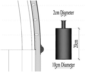
In this situation, a slight decrease in absorption was observed. The cavity resonators are usually installed as shown in Fig. 12 .
|
|
|
Fig. 12. A detailed cross section and installation in a cavity resonator. |
In designing the correct Helmholtz resonator to be installed in the dome, numerous design issues needed to be resolved such as obtaining the right frequency, the number and size of resonators, as well as placement of the damping.
The equations for the resonant frequency were derived assuming open-air conditions. Under a closed room, the interaction between the resonator and the room can alter its resonance frequency, but this effect is marginal and could be neglected (Unnikrishnan et al., 2010 ). In the equation below, f is the resonance frequency, v is the speed of sound in air, A is the surface area of the hole, V is the volume of air in the resonator body, and L is the length of the neck or port.
|
|
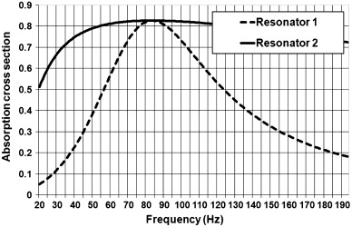
Unnikrishnan et al., 2010 recommend that the resonator volume should not be more than 1% of the room volume. A resonator volume higher than this value does not lead to more absorption. In the Dewela Mosque, the volume in the main prayer hall dome is 3407.913 m3 , and 1% of it is 34.08 m3 . The single resonator volume (Fig. 12 ) is about 0.002 m3 . Thus, a 17,000 resonator should be installed. However, changing the dimensions of the resonator and increasing the volume were not feasible because of the structural constraints of the dome. Thus, 1800 resonators were equally distributed along the inside of the dome hemispherical surface, as shown in Fig. 12 . Ingard (1953) constructed an excel worksheet for the design of acoustic resonators, which is used to calculate the designed resonator absorption with and without internal lining on the resonator base. The results are displayed in Fig. 13 .
|
|
|
Fig. 13. Absorption cross section of designed resonator continuous line with damping. |
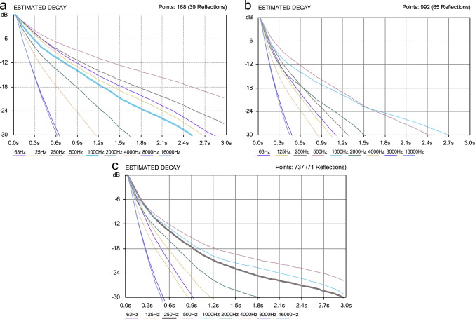
The resonators were designed to provide absorption at a low-frequency range. Other absorptive materials were installed in the ceiling of the three prayer halls to provide the rest of the absorption needed at the mid-frequency range. The model was rerun for the three spaces, and the decay curves after acoustic treatment are shown in Fig. 14 .
|
|
|
Fig. 14. Decay curves after acoustic treatment. (a) Dewela Mosque main prayer, (b) Dewela Mosque daily prayer hall, (c) Damascus City Centre Mosque. |
Based on the RT curves in Fig. 15 , the installation of Helmholtz resonators inside the dome shell, as well as the additional absorptive materials in the ceiling of prayer halls, adjusted the acoustic environment inside the prayer halls to acceptable limits. Fig. 16 shows the RT values of the three prayer halls plotted against the recommended RT values for mosques indicated by Mutbul Kayili (2005) .
|
|
|
Fig. 15. Reverberation time after acoustic treatment. (a) Dewela Mosque main prayer, (b) Dewela Mosque daily prayer hall, (c) Damascus City Centre Mosque. |
|
|
|
Fig. 16. Predicted reverberation time against recommended. |
8. Conclusion
In this work, the acoustic environment of contemporary mosques was evaluated. The sound behavior in mosques lacked adequate research in all relevant technical sciences. As with acoustics, many technical data have yet to be sufficiently evaluated. The common types of mosque designs were discussed and analyzed. A geometrical parametric analysis of three examples of contemporary mosques that represent the three different common configurations of prayer halls was conducted. The prayer halls that have large hemispherical domes have a low-SA/V ratio relative to rectangular prayer halls.
This low-SA/V ratio in prayer halls with hemispherical domes resulted in a reduction of the total absorption of the space. The computer simulation for the three prayer halls with finishing materials specified by each consultant revealed that the materials commonly used for the three design topologies needed acoustic treatment. This treatment will introduce more absorption to the spaces and reduce any negative acoustic phenomena that might occur from having surfaces that focus large amounts of acoustic energy at certain areas of the prayer halls. The decay curves at each frequency revealed that additional absorption was needed at low- and mid-frequency ranges.
The installation of Helmholtz resonators in domes where the scattering of sound attenuates any focusing phenomena, as well as the addition of absorption by changing the ceiling material characteristics-enhanced acoustic quality, indicating that these techniques are effective. A decrease in RT was observed. This decrease was not restricted to the resonant frequency, considering additional damping layers were introduced inside the resonators.
Another effect is the increase in clarity and definition of speech. These effects should be investigated along with the increase in the number of resonators used. On the other hand, the position of the Helmholtz resonators in the corners where the efficiency is greater shows a kind of knowledge on the acoustic behavior of closed spaces by Tilemachos and Dimitris (2007) . This area needs therefore further investigation.
References
- Abdou, 2003 Abdou, A., 2003. Comparison on the acoustical performance of Mosque geometry using computer model studies. In: Eighth International IBPSA Conference, 11–14 August 2003, Eindhoven, The Netherlands.
- Clayden et al., 1975 A.D. Clayden, R.W.D. Culley, P.S. Marsh; Modelling traffic noise mathematically; Applied Acoustics, 8 (1975), pp. 1–12
- Everest, 1994 F.Alton Everest; The Master Handbook of Acoustics; TAB books, McGraw-Hill (1994)
- Hammad, 1990 R. Hammad; RASTI measurements in mosques in Amman; Jordan Applied Acoustics, 30 (1990), pp. 335–345
- Heutschi, 1995 K. Heutschi; A simple method to evaluate the increase of traffic noise emission level due to buildings, for a long straight street; Applied Acoustics, 44 (1995), pp. 259–274
- Holmes and Lyon, 1974 Holmes, G., Lyon, R.H., 1974. A numerical model of sound propagation in urban areas. In: The Second Interagency Symposium on University Research in Transportation Noise, North Carolina State University.
- Ingard, 1953 Uno Ingard; On the theory and design of acoustic resonators; Journal of Accoustics. Society ofAmerican, 25 (1953), p. 1037
- Karabiber, 2000 Karabiber, Z., 2000. A new approach to an ancient subject: CAHRISMA project. In: Proceedings of the 7th ICSV Conference.
- Kayilli, 2005 Kayili, M., 2005. Acoustic Solutions in Classic Ottoman Architecture. Foundation for Science technology and Civilization. May 2005.
- Khateeb and Ismail, 2007 A. Khateeb, M.R. Ismail; Sounds from the past the acoustics of Sultan Hassan Mosque and Madrassa; Journal of Building Acoustics, 14 (2007), pp. 109–132
- Marsilio et al., 2001 Marsilio, M., Prodi, N., Pompoli, R., 2001. On the prediction of reverberation time and strength in mosques. In: Proceedings of the Conference ICA 2001.
- Schmidt-Nielsen, 1984 K. Schmidt-Nielsen; Scaling: Why is Animal Size so Important?; Cambridge University Press, New York, NY (1984)
- Sinan Eserlerinde Akustik, 1989 Sinan Eserlerinde Akustik, 1989. Turk Vakif medeniyeti Cercevesinde “Mimar Sinan ve Donemi Sempozyumu”. Vakiflar Genel Mudurlugu publications, Istanbul.
- One, 2004 Square One, 2004. Ecotect User Manuel, v5.2, Cardiff, UK.
- Unnikrishnan et al., 2010 S. Unnikrishnan, C.D. Shete, A. Subramoniam, K.L. Handoo, C. Padmanabhan; Experimental and computational investigation of coupled resonator–cavity systems; Applied Acoustics, 71 (1) (2010), pp. 61–67 2010
- Vogel, 1988 S. Vogel; Life’s Devices: The Physical World of Animals and Plants; Princeton University Press, Princeton, NJ (1988)
- Tilemachos and Dimitris, 2007 Zakinthinos Tilemachos, Skarlatos Dimitris, 2007. The effect of ceramic vases on the acoustics of old Greek orthodox churches. Applied Acoustics 68 (11–12), 1307–1322.
Document information
Published on 12/05/17
Submitted on 12/05/17
Licence: Other
Share this document
Keywords
claim authorship
Are you one of the authors of this document?

