Abstract
An ideal dental implant is a design that maximizes the anchorage strength of implants in human jawbones and minimizes peak stress values in bone-implant interfaces under given standard loads. The stress concentration at the bone-implant contact is controlled by implant design, which determines the bone biological response. Implant design has improved as a result of marketing demands. The modification of shape, size, material, and surface topography of primary designs has been the focus of dental implant design in response to marketing needs. Since the integration of bone-implant has been highlighted in dentistry investigations, improving implant design depends on the prediction of mechanical reactions and remodeling response of bony tissues around implants. There are four types of implants design including Screws, cylinders, Conical cylinders, and Blades type implants. The major difference between these designs is in implant primary stability. With the development of computational technologies, researchers can predict long term oral bone remodeling around implants by use of the finite element method. This review considers the design parameters of dental implants in which affect stress, strain in bone-implant interfaces, and bone remodeling around the implant.
Keywords: Dental implants, design parameters, implantology, osseointegration
1. Introduction
Dental implants have been used for a few decades; however, implant design has been improved due to marketing desires rather than biomechanical analyses. It seems the dental implant industry will continue to manufacture screw-shaped implants with different thread configurations and dissimilarities in surface roughness. Nevertheless, it is still unclear whether implant design or loading history regulates the bone adaptation algorithm. The effects of loading history might be greater than implant structure for the marginal bone maintenance [1,2].
Dental implants unlike other load-bearing implants (that have orthopedic, oral, and maxillofacial, craniofacial, and plastic and reconstructive purposes); have to play the role of integument to separate the body from oral tissue. Consequently, dental implants not only have to endure the masticatory forces, but they are also expected to withstand other factors such as oral micro-flora, para-functional loads, temperature change, change in pH, and electro-galvanic currents. A combination of these factors with effects of other elements such as implant design, bone density, prosthesis type, and loading history would yield marginal bone loss around dental implants [1,2]. Dental implant systems are used for the replacement of partially or fully edentulous patients. For a single tooth replacement in the molar or premolar region where implants stand in a straight line under large masticatory forces, high strength values for implant material are advised. Implants with lower strength values could be used for full arch replacement where implants are located in a horseshoe formation that provides maximum strength and stability [3,4].
Natural teeth transmit percussive forces through the ligament to the surrounding bone; in contrast, dental implants spread masticatory forces over the implant-bone interface directly, as the ligament is lost in tooth vacation [5]. With the development of computational technologies, nowadays researchers can predict a long-term oral bone remodeling around implants by use of the finite element method (FEM). Even though some studies have compared FEM results with clinical documents such as X-ray images or CT scans, still there is a lack of feasibility and accuracy of remodeling algorithms [6]. Osseointegration is defined as a tight connection between bone and implant, which makes a unit structure under withstanding loads. The implant system is a substitution for missing teeth and oral cavity reconstruction. Osseointegrated dental implants consist of titanium fixture, prosthesis, and abutment. Occlusal forces are transmitted from prosthesis to abutment and then through titanium fixture distributed over the bone-implant interface.
Osseointegrated dental implants were introduced in the 1960s as a direct bone-implant connection in the interface. Through his experimental and clinical investigations, the bony interfacial showed a different reaction to what intervening fibrous tissue was known as the unavoidable result of the insertion of the metal device into the bone. Once the possibility of direct anchorage of metal devices into bone was recognized, the Osseointegration term was rapidly spread in the implant industry. The clinical investigations have shown the success rate of osseointegrated implants depends on the osseointegration degree and level of fibrous integration between bony tissue and implant surface. Bone Implant Contact (BIC) is a measurement method of osseointegration degree in implants. Histomorphometric studies on BIC of immediately loaded implants showed a 40% to 70% osseointegration level in successful osseointegrated dental implants [7]. Clinical studies suggested that the osseointegration pattern of dental implants which describes the actual implant surface involved in osseointegration is more significant than the integration percentage [8]. Since the introduction of osseointegrated dental implants, the popularity of these implants has been increased, however, time dependant bone resorption has been known as a problem and still unavoidable [9,10,11].
2. Dental implant design
Implant design controls the stress concentration at the bone-implant interface and shapes bone biological response. Increasing the roughness of the implant surface would lead to an increase in the contact area and a decrease in stress and strain level in the vicinity of the implant. Though, it should be taken into consideration that magnitude of strains in the bony area surrounding the implant must be kept within physiological levels to preserve bone mass [12].
Current dental implants in the market have been made of metal alloys covered by biocompatible surface coating to improve the healing process and osseointegration. Since the integration of bone-implant has been highlighted in dentistry investigations, improving implant design depends on the ability to predict mechanical reactions and remodeling response of bony tissues around implants [13]. Implants lifetime consists of two phases, unloaded healing period and functional loading phase. Failure could occur in each phase but usually for different reasons. In the healing phase, implant failure could happen in a short period, associated with inflammation. In the second phase, failure occurs under occlusal loading and is usually associated with bone loss [14].
Implant size has a significant role in the retention area in the bone-implant interface. Other factors such as occlusal forces, bone quality, position, and the number of implants, determine the biomechanical status of the implant-bone interface. In a study by Holmgren et al., the distribution of stress is related to implant diameter, shape, and load direction [29]. Implant size could be limited by many reasons such as bone injuries, alveolar bone reduction, wearing of removable dentures, and anatomic structure restrictions for instance nasal cavity, canine fossa, mandibular canal, and antrum. Concerning all of these limitations, implants might lose their capability in the distribution of masticatory forces efficiently [15].
In the case of design, four types of implants are considered: Screws, cylinders, Conical cylinders, and Blade type implants. The major difference between these designs is in implant primary stability. Primary stability provides mechanical strength for the implant to endure early loading with minimum safe micromotions [16]. An ideal dental implant is a design that maximizes the anchorage strength of implants in human jawbones and minimizes peak stress values in bone-implant interfaces under given standard loads. On the other hand, Wolf’s law emphasizes that maximizing stress in the adjacent bone would lead to bone remodeling stimulation. According to Wolf’s law, an optimum implant design maximizes minimum stresses in bone by a standard load upon implant, because minimizing peak stresses increases average stress magnitudes in less stressed regions. Therefore, there is an agreement between the engineering paradigm and Wolf’s law. A dental implant should be designed in a way that high-stress peaks are avoided in the neighboring bone. The greater the applied force results in the higher stress in the surrounding bone [13]. The design of an implant consists of macro-structure and microstructure, which are characterized by basic properties including implant outline, thread shape, abutment connection, surface structural design, and chemical composition [17].
2.1 Thread geometry
The contact area between implant threads and surrounding bones plays a significant role in the stability of the bone-implant interface. Furthermore, thread design has a great influence on stress distribution and marginal bone resorption. In particular, thread pitch and flank angles rule the strength of push in and pull out the capability of implants. Thread height, pitch, and two radii of implant threads have a dominant effect on the fatigue strength of implants. It has been proved that the first thread in the implant neck is the most stressed place and locates the immature osseointegration and initial microfracture [18]. Mechanical and biological fixations determine bone-implant interface stability. Implant thread is the mechanical fixation and provides initial stability for the interface and osseointegration performs as the biological fixation and is responsible for the long-term stabilization of the implant. To provide a mechanical base for masticatory activity, steady osseointegration is required in the interface. Osseointegration in the contact area of threads delivers stability under masticatory activity. The fundamental concerns for implant designers are the dimensions of the contact area and stress distribution over the interface [18].
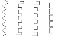
Thread geometry consists of configuration, pitch, and depth. Thread configurations of the conventional implant could be categorized into four basic formations: V shape threads (used by Nobel Biocare, 3I, Paragon, and Lifecore dental implants), reverse buttress (used by Steri-Oss implants), square thread shapes (used by BioHorizons implants), thin threads (used by IMTEC Sendax MDI implants). Branemark implant system (Nobel Biocare as well) has used a V-shape thread configuration to insert into the threaded osteotomy. In 1983, this design was developed to self-tapping to be placed into the cancellous bone in a non-pre-tapped osteotomy site. Later, other modifications such as increasing threads number, expanding threads cutting angle, bigger bone chip space, conical angle, and three cutting edges were added to this implant [18].
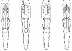
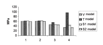
Lee et al. studied on role of thread designs in the distribution of stress. In this work, thread designs were categorized by shape and tapering [19]. Symmetrical, buttressed and square thread configurations plus cylindrical and conical profiles were studied. The measured contact area for the same thread pitch represents a higher contact area for the square threads pattern. Same to other studies, the highest stress was located in the root radii of the first thread. The square shape threads had the least stress concentration. Besides, it was demonstrated that the smaller pitches could lead to a bigger contact area and consequently less stress. However, the peak stress for conical and cylindrical implants appeared almost the same [19]. Geng et al. studied four different thread configurations under the oblique load of 141 N with an angle of 45º inclination in cortical bone, the thread shapes were V-shape (V), thin thread (T), square thread forms of 24 mm (S1), and 36 mm (S2) thread width [18]. Based on this study, the optimal thread configurations are the V shape threads and 36 mm square thread for the stepped screw implant (Figure 1).
|
|
| Figure 1. Four thread-form configurations of stepped screw implant (left) and their bodies (right) [18] | |
Thin thread configuration is used for shortening the implant placement. The reverse buttress thread is designed for pull-out load and has a flat top. For better load distribution, it has been manufactured with different thread pitches and shallower thread depth. Square thread is ideal to reduce shear stress by a factor of 10 and increase compressive resistance. Geng et al. reported that maximum stress concentrations of thin shape threads (T) and smaller square thread configurations (S2) are 190% and 30% more than peak stress values of V-shape and bigger square threads in the bone-implant interface, respectively [18]. Besides, implant thread shape did not have a great influence on stress distribution in cortical bone. On the other hand, trabecular bone is greatly influenced by thread shape configuration. Also, the T-shape thread has the highest stress concentration and the V shape has the lowest (Figure 2).
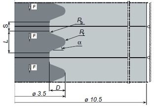
Patra et al. analyzed the design of the Branemark implant [20]. According to the results, tapered design implants demonstrated a higher amount of stress compared with parallel profiles, which appeared to have a more uniform stress distribution. In a finite element study by Chun et al., on optimum thread design of implants; an oblique load of 100 N with 15 degrees inclination was applied, generated stress in cortical bone was higher for plateau thread designs than triangular and square shapes [21]. In a study by Albrektsson et al., a rounded thread top was recommended to avoid stress concentration on thread edges [22]. Van Oosterwyck et al. did a finite element study on Branemark implant system and concluded that when the bone-implant interface is assumed to resist under compressive, tensile, and shear stresses, peak Von-Mises stress concentrations occur outside thread top, however, in a finite element study by Hansson and Werke when the interface was loaded by compressive stresses, peak Von-Mises stresses appeared on the lower flank where passes into curved top [17,23]. The parameters that characterized the thread profile were depth (D), the top radius of curvature (Rt), flank angle (a), the bottom radius of curvature (Rb), and a straight part of length (S) at bottom of the thread. The length of the curved part was designated L (Figure 3). The authors were confident that as long as the top radius of curvature is 10% of thread depth, the accuracy of peak tensile stress is acceptable due to a less favorable element shape. Therefore, a thread depth of 0.1 mm could be as effective as 0.4 mm thread depth if the thread profile is favorable. A small ratio of “top radius of thread over thread depth” will cause high-stress concentration because of the creation of sharp edges [17].
|
| Figure 3. The profile of the thread: Thread depth (D), Top radius of curvature (Rt), Bottom radius of curvature (Rb), Flank angle (a), Straight part at bottom (S) [17] |
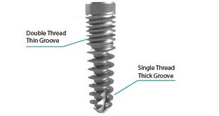
Hansson and Werke concluded that a straight part at bottom of thread has beneficial influence concerning peak values of tensile stress [17]. On the other hand, the straight part led to high compressive stress magnitudes. It was concluded that in most of the dental implants a straight bottom is a disadvantage and a bigger bottom radius of curvature at the bottom would reduce flank support. Therefore, he suggested that for most of the implant design, a straight part at the bottom and a big bottom radius of curvature are of benefit. HDTS dental implant is a unique implant with double thin thread in cortical bone area and single tick thread in cancellous (Figure 4). This exclusive design provides a bigger integrated contact area in the bone-implant interface and a more favorable distribution of load [24]. This design has shown higher stiffness and higher resistance under axial load comparing to classical implant designs. The HDTS implant stiffness is matched with the stiffness of the Branemark implant, which is 180 Kg/mm in cancellous bone.
|
| Figure 4. Hybrid Dual Tread Screw (HDTS) implant [24] |
2.2 Thread pitch
Thread geometry characteristics could be defined by pitch, depth, thickness, helix, and face angle. These factors determine the functionality and biomechanical properties of dental implants. However, most clinical importance is given to thread pitch as the dominant factor in implant function, convenience, and insertion speed. Screw-shape thread configurations are used widely in the implant industry as improved early stability, increased initial contact, maximized interface area, and well dissipation of interfacial stresses [25]. Thread pitch is defined as the number of threads per unit length. Pitch has a very significant role in implant mechanical characteristics, as has a straight influence on the integrated contact area between the threads and bone. Increasing pitch and also thread depth would lead to the improved contact area between bone and implant and can change the biomechanical properties of the implant. The influence of threads can be easily understood as the greater the numbers and depth of threads, the more functional surface area. Thread number influence on stress distribution was less in cortical than cancellous bone. In other words, thread pitch favors stress distribution in cancellous rather than cortical bone. Kong et al. studied the effect of thread pitch on peak Von-Mises stresses [26]. The study covered a range of 0.5 to 1.6 mm. The results demonstrated that thread pitch had more influence on cancellous bone and plays a more significant role under axial load. Kong et al. study suggested that with biomechanical concerns, 0.8 mm thread pitch is an optimum design dimension for screw-shaped dental implants.
2.3 Implant diameter
Measurement of the outermost thread site to the same point on the other side is defined as implant diameter. Conventional implants in the market have a diameter of 3 to 7 mm. The implant platform is measured at the implant-abutment interface and often wider than the implant diameter. The wider implants can increase bone-implant interface and greater engagement with the surrounding bone. Additionally, higher torque needs to be applied in implant surgery. However, the application of a wider implant is subject to residual bone limit and also aesthetic necessities. A wider implant has several advantages such as a higher level of bi-cortical engagement, wider bone-implant interface, more possibility of immediate settlement, and lower stress and strain in abutment. Besides, in severely resorbed maxilla a wider implant can be used as a replacement for bone grafting. Sonic digitizer measurement showed that wider dental implants had more surface contact with the surrounding bone in standard photomicrographs. Increasing diameter from 3 to 4 mm increases implant surface by 35% over the same length. Since more contact area brings more initial stability and more stress resistance. It is believed that implant functional area is more significant than diameter and length [25].
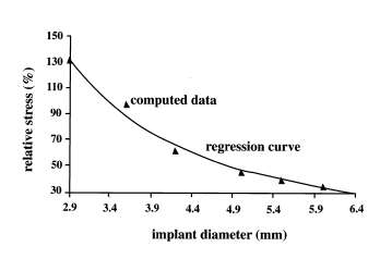
Increasing the diameter of implants can improve strength and increase fracture resistance. Strain analyses tests show that increasing diameter for a standard load can reduce abutment strains. Six mm diameter implants have shown the lowest stress value. However, there is a critical diameter size that must be beaten to reach the minimum peri-implant stress level. Wider dental implants have a better distribution of occlusal forces. Increasing the implant surface would reduce the stress level on the bone-implant interface and any point in the osseointegrated area. Generally, authors consider wider implants as an improvement in implant-bone engagement and less initial micromotion. Studies have shown that implant crown displacement in buccolingual and mesiodistal directions of 5.00 mm diameter compared to 3.75 mm has a 50% reduction. Double bridge implants under off-center standard load had the least mesiodistal movement. In the case of a missing molar tooth in the mandible, dentists can use a wider diameter or a two implants bridge [27]. Himmlová et al. studied implant diameter influence using a standard implant with 12 mm length and 2.9, 3.6, 4.2, 5.0, 5.5, 6.0, and 6.5 mm diameter [28]. The exponential regression curve expresses the relationship between relative stress and diameter (Figure 5). The most noticeable stress relief was about 31% was between 3.6 to 4.2 mm, and a 16.4% reduction between 4.2 to 5.00 mm.
|
| Figure 5. Stress relieve for different implant diameters [28] |
One of the disadvantages of wide implants is the higher possibility of over instrumentation and consequently higher heat generation. Implants with a diameter of less than 5 mm are suggested for the reduction of heat generation in the drilling process and less bone damage. However, it could be concluded that higher heat generation over a larger area of a wider implant so less amount of heat is distributed over each unit area. Though, statistics have shown higher failure rates for 5.00 mm diameter implants than 3.75 mm or 4.0 mm, because wider dental implants are used usually as replacement of failed implants. Narrow diameter dental implants are used for narrow jawbone edges that are too thin for standard implants and also for low interdental width edentulous bones. Mandibular and maxillary incisors are replaced by narrow diameter dental implants. So, narrow-diameter dental implants have less occlusal loading resistance and should be used when axial and tangential loads are small. However, mini implants are different types of implants that have a diameter of less than 2.7 mm. Mini implants are used for the replacement of transitional prostheses (temporary implants) and not fixed ones [25]. Though increasing implant diameter can yield stress reduction, it is more noticeable in cortical bone. So wider diameters would yield less amount of force transmitted to surrounding cortical bone and less bone resorption. An oversized implant invades the available amount of cortical bone and produces an inappropriate amount of stress [29].
2.4 Implant length
The distance between the platform and the apex of dental implants is defined as implant length. In implant dentistry, it is assumed that longer implants are associated with a higher success rate. Though, there is no proven document or investigations that prove the linear relationship between implant success and length. However, a 7 mm length implant has shown the highest failure rate compared to other sizes. Longer dental implants can increase implant stability to a limited certain degree. Since short dental implants have a small contact surface, and occlusal forces need to be contributed over the implant-bone interface area to avoid inappropriate stress levels, short implants are not recommended in dentistry. In a finite element study of Lee et al., it is shown that masticatory forces generate stress over the cortical bone interface and not the cancellous area [25]. Since occlusal forces are usually small in amount, cortical bone can tolerate the generated stress. Therefore, implant diameter especially in the crestal bone area is a more important factor compared to the length. Clinical reports have shown a high failure rate for implants shorter than 7 mm. It is believed that bone type and interface area are more significant parameters in implant stability than implant length. It should be taken into consideration that short dental implants are usually used for the posterior maxilla that has lower bone quality [25].
In a study by İplikçioğlu and Akça, lower compressive and tensile stresses were seen for wider implants and it was concluded that length does not decrease stress values [30]. In this study, stress levels in two wide supported implants with a diameter of 4.1 mm have been compared with three implants supported prostheses with a 3.75 mm diameter. The magnitude of stress distribution in the surrounding cortical bone was lower for the two-unit supported implants than the three units. The results showed that wider diameter has the greatest effect on stress level and changes in length and number of units do not decrease the magnitude of stress.
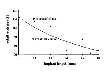
In a Finite element study by Himmlová et al., a three-dimensional simulation of implants with different lengths of 8 mm, 10 mm, 12 mm, 14 mm, 16 mm, 17 mm, and 18 mm with a diameter of 3.6 mm, were placed in the simulated jawbone with vertical alignment [28]. Based on the results, over 10 mm range of implant length, level of stress relief become much less than implant diameter. Stress level variations between 8 mm and 17 mm are about 7.3% (Figure 6). A similar path trend for stress level is seen for both diameter and length. However, there was a smaller effect of implant length than the implant diameter. There are a few studies that give more importance to implant length than diameter; however, most of the observations have proved less influence of length than the diameter in stress dissipation.
|
| Figure 6. Stress relieve for different implant length [28] |
3. Implant outline
Implant design defines a three-dimensional (3D) structure that includes implant shape, thread configuration, abutment, surface chemical composition, and topography. Implant design is considered to have a significant influence on the contribution of stress. Implant designs can be categorized as Root form, Blade, and Sub-periosteal dental implants. The conventional implants are root-form screw or cylinder implants with hollow or solid shapes. Most modifications on screw shape dental implants have been given to the crystal and apical part of the implant to reduce heat generation and ease self-tapping. Implant designs have been developed to imitate teeth anatomy, such as stepped cylindrical implants that have similarities to tooth roots at both apical and cervical segments. The stepped cylindrical implants have less level of stress distribution compared to cylindrical and tapered dental implants, and also these designs improve loading resistance in cortical bone [25].
Steigenga et al. studied the effects of dental implant design on the strength of osseointegration and quality of bone-implant interface [31]. The dental implant's strength consists of geometry, mechanical properties, initial stability, and long-term osseointegration. Design factors can be used to increase strength, stability, and load transfer. Implant design, material biocompatibility, surface, host bone quality, surgical technique, and loading history are significant factors in bone-implant interface strength. Siegele et al. studied the distribution of stress under a standard vertical load for different implant designs [32]. They concluded surfaces with geometric discontinuities and a slight range of curvature, like stepped designs, present a higher level of stress compared to cylindrical or screw shape dental implants. This study showed that peak stress level for a standard lateral load is concentrated in the soft tissue region for cylindrical implants and the first thread of screw implants.
The design evolution of dental implants has been focused on modification of shape, size, material, and surface topography of primary designs, based on marketing demands rather than scientific researches. Though the relationship between load and stress magnitude could be defined in a formula, geometry has a complex structure that does not allow a simple formula for the relationship of design geometry and stress distribution. In a finite element study by Bozkaya et al., the effects of external geometry of 5 conventional dental implants in the distribution of occlusal forces were studied [33]. Ankylos, Astra, Bicon, ITI, and Biocare dental implants were simulated and analyzed under an occlusal load of 300 N as moderate force and greater than 1000 N for extreme cases.
3.1 Anchorage
In a study by Hsu et al., conical dental implants showed higher insertion torque and also greater pullout strength compared to cylindrical implants [34]. Based on the results, conical screw shape dental implants require a higher level of insertion torque and also pullout force than cylindrical implants and this characteristic would be emphasized by increasing the foam bone density. As expected, a bigger outer diameter provided a wider bone-implant contact area and consequently higher interface stiffness and also more pullout strength. However, there are many studies on the comparison of conical and cylindrical with different conclusions. For instance, in a study by Kwok et al., higher insertion torque was seen for conical implants but similar pullout strength for conical and cylindrical implants [35]. In studies of Abshire et al. and Ono et al., with the same geometrical properties, greater pullout strength was reported for tapered than cylindrical implants [36,37]. Choi et al. study stated higher pullout strength for tapered shape than straight cylindrical implants [38]. In a study by Lill et al., the pullout strength of conical and cylindrical implants under cyclic load was measured and reported lower pullout strength for conical than cylindrical implants [39]. The difference in results could be because of the dissimilar experiment methodology, different bone quality, and other involved factors in the experimental pullout test.
In a study by Cehreli et al. on Branemark, ITI, and Astra Tech dental implants, compressive and tensile strain under vertical and oblique loads of 100 and 150 N were measured [1]. According to Saint Venant’s principle, when the load distribution at the end of a structure is changing while the resultant load is constant, only the stress magnitudes in the adjacent area close to the end will change. Therefore, the position and amount of stresses in the marginal bone surrounding the implant are essential. Consequently, conical designs demonstrated lower stress magnitudes than cylindrical designs according to finite element results. He reported insignificant differences between cylindrical and conical implants under 100 N and 150 N loads for Astra Tech, Branemark, and ITI. However, these results approve an even slightly better distribution of strain and stress for conical shapes compared to cylindrical ones with the same geometrical characteristics [1,2].The study of Hsu et al. exhibited a linear relationship between mineral bone density with pullout strength and insertion torque [34]. The higher the bone density, the more significantly higher pullout and insertion torque for conical shape implants. Tapered design implants in denser bone compared to straight cylindrical implants could better compact the bone in the insertion process and show higher maximal pullout strength. The obtained results demonstrate that the maximal insertion torque is related to the pullout strength [34]. Rieger et al. conducted a finite element study on conical shape dental implants. Based on his findings, the conical shape implants with high elastic modulus are the most suitable choice for singular implants [40]. It was concluded that tapered design dental implants with a high module of elasticity are the most appropriate implants; however, to avoid bone resorption the design must be in a way to reduce the peak stress concentration in the implant neck. In another study, Rieger et al. concluded that tapered dental implants are a better choice than cylindrical implants in case of punching stresses [41]. He reported that truncated retentive elements such as fins, threads, or serrations are a better choice than the un-truncated ones.
3.2 Abutment and crown
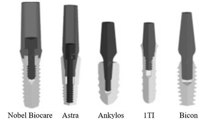
A dental implant consists of an implant root that is placed into the jawbone; an abutment that connects the dental prosthesis to the main body once the implant is osseointegrated successfully with the bone. The implant abutment connection could be a screw or clamped mechanism that depends on the design structure. There are two types of implant-abutment mating systems; screw system and tapered-interface fit which is also called Morse taper. In Figure 7, different abutment systems of commercial dental implants are displayed. Branemark and Astra implant systems have screw-type mating, Ankylos and ITI use a screw with a tapered ending system, and Bicon only uses tapered-interface fit [42].
|
| Figure 7. Different implant–abutment attachment methods [42] |
In the screw-type system, the connection is established by a specific amount of torque during the installation of the abutment into the implant. The tapered-interface fit system secures the connection by contact pressure coming from friction in the interface. Screw loosening, when the occlusal loads exceed the threshold and screw creep deformities are the clinical disadvantages of a screw-type mating system. However, screw loosening is not a common issue between tapered fit interface abutments. Also, occlusal loads assist implant-abutment connection as they perform in the abutment insertion direction. Only pullout force and loosening torque are considered as disconnection mechanisms for this mating system fit.
Burguete et al. suggested that the implant abutment mating system should be designed in a way that minimizes shear stress and strain magnitudes at the interface [43]. The mechanical and biomechanical characteristics of the interface fit the mating system depending on the surface material, coefficient of friction, contact area, tapered angle, diameter, and insertion depth. The amount of 45 N.cm torque is recommended for abutment screw tightening. In an experimental study, different tightening torque of 25, 30, 35, and 40 N.cm were applied to observe the influence on abutment screw loosening. This study suggested that the application of tightening torque of a minimum of 30 N.cm improves the implant-abutment connection stability [25].
Friction and lock mechanism are the principal factors in the Morse taper abutment connection. In the screw mating system, abutment threads are responsible to secure the connection under occlusal forces. However, in the interface fit system, masticatory loads are tolerated by the tapered design of the mating system to keep the abutment balanced. High normal stress is expected over the contact area of a tapered interface fit system that stabilizes the implant abutment position by the use of friction. In a screw-type mating system, a compressive force is applied to tighten the abutment screw and make a contact between implant abutment threads' surface. Abutment stretch capacity, tightening load, and maintenance of the tightening preload are the determinant factors in screw joint success. Screw loosening and low tightening preload would threaten joint stability and yield to clinical failure. The most important reasons for joint unsteadiness are insufficient preload, unsatisfactory screw design, weak element fit, poor surface roughness, disproportionate loading, and bone elasticity. Because of the tapered interface fit characteristic, occlusal forces perform in appropriate direction that keeps the abutment and secures the connection, so screw loosening is not a complication. Any external pullout force which is smaller than tightening preload would increase the tensile stress and decrease the compressive stresses on the implant. To reach this balance in the screw joint, the tightening preload must be kept within a limited amount that does not allow the joint to open up.
Conclusion
Dental implants are used to replace partial or fully edentulous patients. The dental implant industry will probably produce screw-shaped implants with different thread configurations and dissimilarity in surface roughness. The marketing demands have caused improvement in implant design. According to marketing demands, the design of dental implants has concentrated on modification of shape, size, material, and surface topography of primary designs. Since the introduction of osseointegrated dental implants, the popularity of these implants has been increased, however, time dependant bone resorption is inevitable. Implant design controls the stress concentration at the bone-implant interface and shapes bone biological response. The growth of the roughness of the implant surface causes an increase in the contact area and a reduction in stress and strain level in the vicinity of the implant. The magnitude of strains in the bony area surrounding the implant must be kept within physiological levels to preserve bone mass. At present, dental implants in the market are made of metal alloys covered by biocompatible surface coating to enhance osseointegration and the healing process. Since the integration of bone-implant has been highlighted in dentistry investigations, improving implant design depends on the prediction of mechanical reactions and remodeling response of bony tissues around implants.
Acknowledgement
We acknowledge Global College of Engineering and Technology of Oman for supporting this study.
References
[1] Cehreli M., Duyck J., Cooman M.D., Puers R., Naert, I. Implant design and interface force transfer. Clinical Oral Implants Research, 15(2):249-257, 2004.
[2] Çehreli M., Şahin S., Akça K. Role of mechanical environment and implant design on bone tissue differentiation: current knowledge and future contexts. Journal of Dentistry, 32(2):123-132, 2004.
[3] Christensen G.J. Implant prosthodontics: from single tooth to complex cases. Journal of Oral Implantology, 28(5):244-248, 2002.
[4] Haas R., Mailath‐Pokorny G., Dörtbudak O., Watzek G., Polak C., Fürhauser R. A long‐term follow‐up of 76 Brånemark single‐tooth implants. Clinical Oral Implants Research, 13(1):38-43, 2002.
[5] VanSchoiack L.R., Wu J.C., Sheets C.G., Earthman J.C. Effect of bone density on the damping behavior of dental implants: An in vitro method. Materials Science and Engineering: C, 26(8):1307-1311, 2006.
[6] Li W., Lin D., Rungsiyakull C., Zhou S., Swain M., Li Q. Finite element based bone remodeling and resonance frequency analysis for osseointegration assessment of dental implants. Finite Elements in Analysis and Design, 47(8):898-905, 2011.
[7] Chou H., Jagodnik J.J., Müftü S. Predictions of bone remodeling around dental implant systems. Journal of Biomechanics, 41(6):1365-1373, 2008.
[8] Papavasiliou G., Kamposiora P., Bayne S., Felton, D. 3D-FEA of osseointegration percentages and patterns on implant-bone interfacial stresses. Journal of Dentistry, 25(6):485-491, 1997.
[9] Åstrand P., Engquist B., Dahlgren S., Gröndahl K., Engquist E., Feldmann H. Astra Tech and Brånemark system implants: a 5‐year prospective study of marginal bone reactions. Clinical Oral Implants Research, 15(4):413- 420, 2004.
[10] Moberg L., Sagulin G., Köndell P., Heimdahl A., Gynther G.W., Bolin A. Branemark system and ITI dental implant system® for treatment of mandibular edentulism. Clinical Oral Implants Research, 12(5):450-461, 2001.
[11] Steenberghe D., Mars G., Quirynen M., Jacobs R., Naert I. A prospective split‐mouth comparative study of two screw‐shaped self‐tapping pure titanium implant systems. Clinical Oral Implants Research, 11(3):202-209, 2000.
[12] Frost H.M. Wolff's law and bone's structural adaptations to mechanical usage: an overview for clinicians. The Angle Orthodontist, 64(3):175-188, 1994.
[13] Morgan M., James D. Force and moment distributions among osseointegrated dental implants. Journal of Biomechanics, 28(9):1103-1109, 1995.
[14] Himmlová L., Dostálová T., Kácovský A., Konvic̆ková S. Influence of implant length and diameter on stress distribution: a finite element analysis. Journal of Prosthetic Dentistry, 91(1):20-25, 2004.
[15] Wiskott H., Belser U.C. Lack of integration of smooth titanium surfaces: a working hypothesis based on strains generated in the surrounding bone. Clinical Oral Implants Research, 10(6):429-444, 1999.
[16] Skalak R. Biomechanical considerations in osseointegrated prostheses. Journal of Prosthetic Dentistry, 49(6):843-848, 1983.
[17] Hansson S., Werke M. The implant thread as a retention element in cortical bone: the effect of thread size and thread profile: a finite element study. Journal of Biomechanics, 36(9):1247-1258, 2003.
[18] Geng J., Ma Q., Xu W., Tan K., Liu G. Finite element analysis of four thread‐form configurations in a stepped screw implant. Journal of Oral Rehabilitation, 31(3):233-239, 2004.
[19] Lee C., Lin S., Kang M., Wu S., Fu P. Effects of implant threads on the contact area and stress distribution of marginal bone. Journal of Dental Sciences, 5(3):156-165, 2010.
[20] Patra A.K., DePaolo J.M., D’Souza K.S., DeTolla D., Meenaghan M.A. Guidelines for analysis and redesign of dental implants. Implant Dentistry, 7(4):355-368, 1998.
[21] Chun H.J., Cheong S.Y., Han J.H. Evaluation of design parameters of osseointegrated dental implants using finite element analysis. Journal of Oral Rehabilitation, 29:565−74, 2002.
[22] Albrektsson T., Branemark P.I., Hansson H.A., Kasemo, B. The interface zone of inorganic implants in vivo: titanium implants in bone. Annals in Biomedical Engineering, 11:1–27, 1983.
[23] Van Oosterwyck H., Duyck J., Van der Sloten J., Van der Perre G., De Cooman M., Lievens S., Puers R., Naert I. The influence of bone mechanical properties and implant fixation upon bone loading around oral implants. Clinical Oral Implants Research, 9:407–418, 1998.
[24] Arni U., Weissberg I., Gihon O. Hybrid dual thread screw implant-analytical and experimental research. ARDS Implants, 2007.
[25] Lee J., Frias V., Lee K., Wright R.F. Effect of implant size and shape on implant success rates: a literature review. Journal of Prosthetic Dentistry, 94(4):377-381, 2005.
[26] Kong L., Zhao Y., Hu K., Li D., Zhou H., Wu Z., Liu B. Selection of the implant thread pitch for optimal biomechanical properties: a three-dimensional finite element analysis. Advances in Engineering Software, 40(7):474-478, 2009.
[27] Geramy A., Morgano S.M. Finite element analysis of three designs of an implant-supported molar crown. Journal of Prosthetic Dentistry, 92(5):434-440, 2004.
[28] Himmlová L., Dostálová T., Kácovský A. Konvic̆ková S. Influence of implant length and diameter on stress distribution: a finite element analysis. Journal of Prosthetic Dentistry, 91(1):20-25, 2004.
[29] Holmgren E.P., Seckinger R.J., Kilgren L.M. Mante F. Evaluating parameters of osseointegrated dental implants using finite element analysis-a two-dimensional comparative study examining the effects of implant diameter, implant shape, and load direction. Journal of Oral Implantology, 24(2):80-88, 1998.
[30] İplikçioğlu H., Akça K. Comparative evaluation of the effect of diameter, length and number of implants supporting three-unit fixed partial prostheses on stress distribution in the bone. Journal of Dentistry, 30(1):41-46, 2002.
[31] Steigenga J.T., Al-Shammari K.F., Nociti F.H., Misch C.E., Wang H. Dental implant design and its relationship to long-term implant success. Implant Dentistry, 12(4):306-317, 2003.
[32] Siegele D., Soltesz U. Numerical investigations of the influence of implant shape on stress distribution in the jaw bone. International Journal of Oral & Maxillofacial Implants, 4(4):333-340, 1989.
[33] Bozkaya D., Muftu S., Muftu A. Evaluation of load transfer characteristics of five different implants in compact bone at different load levels by finite elements analysis. Journal of Prosthetic Dentistry, 92(6):523-530, 2004.
[34] Hsu C., Chao C., Wang J., Hou S., Tsai Y., Lin J. Increase of pullout strength of spinal pedicle screws with conical core: biomechanical tests and finite element analyses. Journal of Orthopaedic Research, 23(4):788-794, 2005.
[35] Kwok A.W.L., Finkelstein J.A., Woodside T., Hearn T.C., Hu R.W. Insertional torque and pull-out strengths of conical and cylindrical pedicle screws in cadaveric bone. Spine, 21(21):2429-2434, 1996.
[36] Abshire B.B., McLain R.F., Valdevit A., Kambic H.E. Characteristics of pullout failure in conical and cylindrical pedicle screws after full insertion and back-out. The Spine Journal, 1(6):408-414, 2001.
[37] Ono A., Brown M.D., Latta L.L., Milne E.L., Holmes D.C. Triangulated pedicle screw construct technique and pull-out strength of conical and cylindrical screws. Journal of Spinal Disorders, 14:323-329, 2001.
[38] Choi W., Lee S., Kim J.W., Kim J.K., Goel V. Assessment of pullout strength of various pedicle screw designs in relation to the changes. In: 48th Annual Meeting of the Orthopaedic Research Society, 2002.
[39] Lill C.A., Schlegel U., Wahl D., Schneider E. Comparison of the in vitro holding strengths of conical and cylindrical pedicle screws in a fully inserted setting and backed out 180 degrees. Journal of Spinal Disorders, 13:259-266, 2000.
[40] Rieger M., Adams W., Kinzel G. A finite element survey of eleven endosseous implants. The Journal of Prosthetic Dentistry, 63(4):457-465, 1990.
[41] Rieger M., Fareed K., Adams W., Tanquist R. Bone stress distribution for three endosseous implants. The Journal of Prosthetic Dentistry, 61(2):223-228, 1989.
[42] Bozkaya D., Müftü S. Mechanics of the tapered interference fit in dental implants. Journal of Biomechanics, 36(11):1649-1658, 2003.
[43] Burguete R.L., Johns R.B., King T., Patterson E.A. Tightening characteristics for screwed joints in osseointegrated dental implants. The Journal of Prosthetic Dentistry, 71(6):592-599, 1994.Document information
Published on 07/03/22
Accepted on 24/02/22
Submitted on 26/09/21
Volume 38, Issue 1, 2022
DOI: 10.23967/j.rimni.2022.03.002
Licence: CC BY-NC-SA license
Share this document
Keywords
claim authorship
Are you one of the authors of this document?
