Abstract
The finite formulation of the 4-node thin shell element based on Co-rotational (CR) and Timoshenko's theory was presented for the analysis of laminated composite structures. Based on the Timoshenko's theory the present thin shell element avoids shear locking behavior, and a bilinear in-plane displacement field is introduced for the coupling of in-plane and bending actions, and such element performs simple formulation and highly efficienct. A highly efficient CR formulation was also established to define the motion of the element with large displacement. The characteristics of the element are more pronounced when shells get thin, each node of the 4-node element has five degrees of freedom. An incremental iterative method based on the Newton Raphson method was used to solve the nonlinear equilibrium equations. A number of numerical examples were given to verify that the formula is computationally efficient and the results showed good agreement.
1. Introduction
Many nonlinear shell element formulations are based on the total Lagrangian (TL) and update Lagrangian (UL), including complex formulations and increasing calculation interval. However, in order to maximum the computational efficiency, a nonlinear finite element method (FEM) is required. A named “CR” approach was introduced by Wempner [1] and Belytschko [2] firstly.
As a new method for improving the computational efficiency of nonlinear element with large displacement problems, the CR has attracted more and more researchers in the last decade. The core of the method is to decompose the analytic process of the element into large displacement and large rotation of the rigid body and local small deformation. When the CR method is used in the process of structural geometric nonlinear analysis, the deformation in the local coordinate system reflects the small strain of the element. However, the translation and rotation of the rigid body reflects the large displacement of the element.
Most of the studies mainly apply the CR method to beam and shell structures. Crisfield et al. [3] based on the CR method to establish a universal model for the analysis of beam, shell and solid structure, the formulas used to build the model are simpler than many of the earlier procedures. Afterwards Hsial et al. [4] and Wen et al. [5] established an axisymmetric thin-walled beam element with second-order accuracy using CR and TL formulation. Tham et al. [6] analyses multi-layered composite plate and shell structures using CR kinematic framework. Cortivo et al. [7] carried out plastic buckling and failure analysis for thin shell structures using CR and ANDES finite element formulations. A triangular shell element formula based on CR method has been obtained by Nour-Omid et al. [8], and then Pacoste [9] and Eriksson et al. [10] developed the instability analysis of the shell structure using the established triangular plate element CR formulations, the difference between them is the parameterization of the rotations.
In order to improve the computational efficiency, Battini [11] introduced three modifications in the CR framework, including local rotations, the number of element local degrees of freedom from 18 to 15 and the parameterization of the global finite rotations. Kim et al. [12] believes that the actual superimposition and the correction factor are not necessary and improve the the transverse shear stiffness, according to it Kim et al. [13] introduced the ANS method and CR formulation with second order accuracy and defines the transverse shear stiffness. To ensure computational efficiency, Kim et al. [14] also improved the 4-node shell element by combining an EAS and ANS. Nowadays, this approach based on beam [15,17,19], rod [18] and shell [16] element is widely used in many fields.
The purpose of the paper is to improve the computational efficiency of the thin shell structures modelling by a high efficiency nonlinear 4-node thin shell element. In the local element formulation, a simple and high efficiency laminated composite element was presented et al. [20], the tangential rotation and the shear strain were obtained by Timoshenko laminated composite beam theory, and a bilinear in-plane displacement field was introduced for the coupling of in-plane and bending actions. In order to consider the movement of the element with large translation and rotation, a highly efficienct CR method was obtained. In the current work, the main idea introduced by Pacoste [9] and Battini [11] was employed. At last, a high efficiency tangent stiffness matrix of 4-node thin shell element was obtained in this paper.
2. Local deformation
In local coordinate, Cen [20] show that tangential rotation and shear strain were obtained by Timoshenko beam theory. Shear strain and rotation fields within the element are then determined by improved rational interpolation, and a bilinear displacement field is introduced for the coupling of in-plane and bending actions. Finally, in order to analyze random laminated composite structures, the 20 degrees of freedom quadrilateral bending element can be used.
2.1 Element shear strain and in-plane strain field of the mid-plane
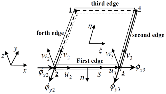
As shown in Figure1, the local deformational displacements and rotations for random 4-node elements can be written as
|
|
(1) |
|
| Figure 1: Local displacement and rotation at the mid-plane of a laminated composite element. |
based on the local deformation of the element mid-plane, displacement and rotation of random point for the elmenet can be written as
|
|
(2) |
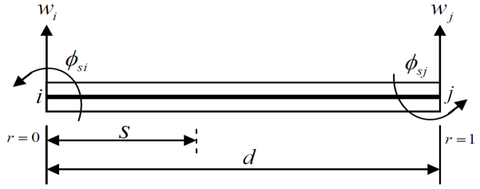
The element is shown in Figure 2. Based on Timoshenko beam theory, the tangential rotation and the shear strain along each element side can be written as
|
|
(3) |
|
|
(4) |
with
|
|
(5) |
|
| Figure 2: Laminated composite beam element. |
Based on the Equation (4), element shear strain of every edge can be written as
|
|
(6) |
with
|
|
(7) |
where is the length of element edge, is the y orientation distance between two adjacent nodes, is the orientation distance between two adjacent nodes. , are the shear and bending stiffness.
According to the element shear strain of every edge , can be written as
|
|
(8) |
Based on the geometrical relationship of two adjacent edges, shear strain on the crossing point 1 can be written as
|
|
(9) |
Shear strain of the other nodes can be written similarly. So shear strain field can be written as
|
|
(10) |
with
|
|
(11) |
2.2 Rotation and in-plane displacement field
The element normal and tangential of the first edge is shown in Figure 1, each edge of the element is assumed to be linearly distributed.
Based on the Equation (3), the normal and tangential rotations of the first edge can be written as
|
|
(12) |
Normal and tangential rotations of the other edges can be obtained similarly.
In global coordinate, Normal and tangential rotations of the midpoint on the first edge are represented as
|
|
(13) |
Element rotation field can be written as
|
|
(14) |
with
|
|
(15) |
The bilinear in-plane displacement and can be written as
|
|
(16) |
where are the quadrilateral element shape functions.
2.3 Element in-plane strain and curvature field of the mid-plane
Element in-plane strain can be written as
|
|
(17) |
with
|
|
(18) |
According to section 2.2, element curvature field can be given
|
|
(19) |
where is bendding strain matrix.
Based on the constitutive equation of laminated composite plate, the relationship between strain and displacement in mid-plane can be written as
|
|
(20) |
2.4 Element stiffness matrix
The stiffness matrix of the 4-node element is derived from the principle of minimum potential energy, element shear strain and in-plane strain field:
|
|
(21) |
where shear strain matrix and in-plane strain matrix of the mid-plane can be found in Equations (10) and (20), respectively, is stress-strain matrix of laminated composite plate, is shear stiffness, and is the Jacobian determinant. The element stiffness matrix was reduced to a matrix, which was calculated by Gauss integral.
3. Co-rotational formulation
CR approach is more efficient than TL and UL to analyze thin wall structure models. Based on CR description, a lot of plate and shell elements including 3 node and 4 node were established and confirmed by many numerical illustrations and tests. According to CR description, element kinematics from initial undeformed to final deformed attitude can be divided into two sections [7]. The first section is rigid rotation removing deformational part.and translation. The second step is a local deformation and rotation under local coordinate system. Element deformation displacement and rotation were established conveniently in section 2.
3.1 Parameterization of the rigid rotations and coordinate systems
In order to represent large three-dimensional rotations, a parameterization approach of the rigid rotations is introduced [9]. Orthogonal matrix can be obtained by three separate parameter variables. Firstly, the rotational vector can be defined by
|
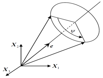
According to the definition above, as shown in Figure 3, rotation can be obtained by an angle defined by the unit vector . So the value of is obtained by
|
|
(23) |
where () are the components of .
|
| Figure 3: Rotational vector. |
In terms of the definition above, the orthogonal matrix can be written as
|
|
(24) |
Based on the conception of the rigid rotation, the global rotation matrix at point can be defined by .
|
(25) |
|
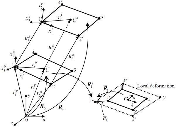
| Figure 4: Element kinematics and coordinate systems. |
As shown in Figure 4, we define as the vectors of the local frame in the current deformed configuration. Then, the matrix [9] defining rotations can be obtained as
|
|
(26) |
with
|
|
(27) |
where and denote displacement from the initial to current coordinate, respectively. and denote displacement vector of initial nodes and in the global system, respectively. and denote displacement vector along the orientations and of the line connecting two nodes, respectively.
The local deformation of point can be expressed by , as shown in section 2. According to the define of rigid frame in the local coordinate, can be redefined as
|
|
(28) |
As shown in Figure 4, noting that , the local rotations are defined by the matrices
as
|
(29) |
The differentiation can be given by
|
|
(30) |
where , , and the corresponding associated vectors , , denote spatial angular variations, which superimposed onto orthogonal matrices , and .
Using Equations (28), (29) and (30), the differentiation of Equations (28) can be given as
|
|
(31) |
with
|
|
(32) |
The differentiation of Equation (30) can be given as
|
|
(33) |
According to Equations (30) and (33), the following expression is obtained as
|
|
(34) |
3.2 Transformation matrix
The transformation matrix is needed to convert the internal force and tangent stiffness matrix. In the global coordinate, the 4-node element displacement is defined as
|
|
(35) |
where are the global displacement vectors of the nodes, denotes the spatial angular variations, defined in Equation (30).
Referring to Equations (23), (25) and (30), the transformation matrix was defined by
|
|
(36) |
with
|
|
(37) |
where are the components of , is the unit diagonal matrix.
Using Equations (31), (32) and (34), the matrix can be written as
|
|
(38) |
The blocks is the matrix removing deformational part:
|
|
(39) |
where is the unit diagonal matrix. can be found in section 3.1. , , and more detail process of the element kinematics are defined by local and global displacement and rotation vector [9,11].
According to the rotate transformation relation obtained by the change of variables from to .
|
|
(40) |
Using Equations (38) and (40), the final transformation matrix is obtained as
|
|
(41) |
3.3 Element internal force and tangent stiffness matrix
According to the transformation matrix in section 3.2, the element global internal force can be defined as
|
|
(42) |
where and denote the internal force vector of the node for translation and rotation, respectively. The internal force of local deformation is defined and expressed in [20].
The element local stiffness matrix and established transformation matrix by CR can be found in sections 2.3 and 3.2, Using Equations (21) and (41), the element global tangent stiffness matrix is defined as
|
|
(43) |
with
|
|
(44) |
In Equation (43), the element tangent stiffness matrix is reduced from a matrix to a matrix. In Equation (44), the denotes zero matrix, Equation (44) is explained in detail in [11].
4. Numerical experiments
The 4-node thin shell element is used to carry out linear and geometrically nonlinear analysis. This part is mainly to assess the accuracy and efficiency of the element by numerical experiments. All of the numerical results are compared with references and standard 4-node (QUAD 4) thin shell element, which is established and extensively used based on standard updated Lagrangian formulation (UL). The standard 4-node thin shell element tangent stiffness matrix is still a 24×24 block. Generally speaking, the results from the standard finite element with small grid can be used as the standard of structure design. So the numerical results from the present element can be compared with the results of the QUAD 4, for which the model can be divided into grids small enough. At the same time, the convergence feature of the present method was also verified by analytical solution for simply supported orthotropic symmetry plates.
4.1 Linear analysis
4.1.1 Simply supported laminated composite plates
All edges are provided with a simple supported restraint and a uniform load applied to the surface. The plate with meshes is used in the analysis. The geometry and material properties of T700S/5405 can be obtained as
|
|
The center deflections are presented in the non-dimensional form using the equation [14]
|
|
(45) |
and are compared with standard element and analytical solution in Table 1. The ply stacking sequence and ply angle influence the stiffness and strength of laminated composite plate in aircraft structural design. Hence, the laminated composite plate is more designable than isotropy plate.
| Analytical solution | standard element () | Present element () | |
| [45/-45]s | |||
| [90/0]s |
4.1.2 Simply-supported laminated composite plates
The plate with meshes is used in the analysis. Aspect ratio () is used to verify present element. The relevant parameters are as follows:
|
|
Maximum displacements are obtained using the equation (45), and are compared with the strandard element and the references by Kim et al. [13-14] and Pucha et al. [21] in Table 2. The results show that present element can be well applied to the analysis of the actual engineering structure.
| Solution method | Mesh | 5/-5 | 15/-15 | 30/-30 | 45/-45 |
| Present | 7.083 | 9.34 | 10.77 | 10.25 | |
| Strandard element (UL) | 7.145 | 9.82 | 10.36 | 10.17 | |
| Kim et al. [13] | 7.015 | 9.505 | 10.52 | 10.12 | |
| Kim et al. (EAS-ANS) [14] | 7.025 | 9.468 | 10.56 | 10.16 | |
| Pucha et al. [21] | 7.1298 | 9.1077 | 9.1718 | 9.0793 |
4.1.3 Simply supported laminated spherical shell
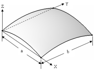
A laminated spherical shell shown in Figure 5 is analyzed. The surface of the structures is applied with a uniform load. meshes are used to analyze the spherical shell structure with lay-ups of (0/90/0/90/0/90/0/90/0). The relevant parameters are used as follows:
|
|
|
| Figure 5: Geometry proprieties of laminated spherical shell. |
The center deflection of the laminated spherical shell structure is compared with the non-dimensional form (as shown in Equation (45)) of the standard element and the references by Kim et al. [13,14] and Noor et al. [22]. The results are tabulated in Table 3.
| Solution method | Mesh | Non-dimensional center deflection |
| Present | 5.874E-05 | |
| Standard element (UL) | 5.92E-05 | |
| Kim et al. [13] | 5.844E-05 | |
| Kim et al. (EAS-ANS) [14] | 5.890E-05 | |
| Noor et al. [22] | 5.916E-05 |
4.2 Nonlinear analysis
4.2.1 Laminated composite plate
A multi-layer laminated composite plate is used to nonlinear analyze. meshes and lay-ups of [45/-45/0/0/45/-45/90/90] are used in this analysis. The length of the plate is . The total thickness is . All edges are clamped. The surface of the structures is applied with a uniform load. The material properties are used as follows:
|
|
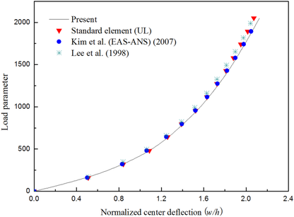
Maximum displacements of the plate is compared with that of the standard element with meshes and the references by Kim et al. [14] and Lee et al. [23]. The results are shown in Figure 6, normalized deflection: .
|
| Figure 6: Load-deflection curve of laminated composite plate. |
4.2.2 Pinched cantilever cylinder
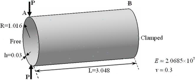
In this example, nonlinear analysis of pinched cantilever cylinder is carried out. The cylinder is depicted in Figure 7, which clamped at B face and applied two opposite loads at A face. regular meshes are used to analyze the structure.
|
| Figure 7: Pinched cantilever cylinder. |
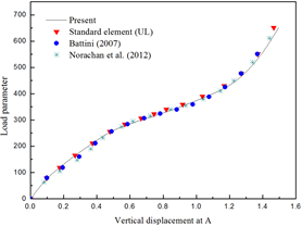
It is clear that this example reflects the nonextensional deformations for the element, this phenomenon will not occur in actual engineering. By the large deformation analysis, the vertical displacement at A of the cantilever cylinder is compared with that of the standard element (UL) with and the references by Battini [11] and Norachan et al. [24] as shown in Figure 8. The results analyzed by present element showed a satisfied precision and efficiency.
|
| Figura 8: Load-displacement curve of cantilever cylinder. |
4.2.3 Double-curved thin shell structure
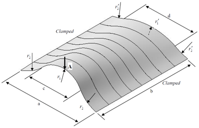
Double-curved thin shell structure can be seen everywhere in the actual project. The numerical example is to use present element to carry out the nonlinear analysis of the double-curved structure, which is always used in many engineering structures and shows significant different nonlinear. meshes and lay-ups of are used in this analysis. The length of and width of are shown in Figure 9, and the radius of the two sides in the direction of width are , and , , respectively, the length of the section with radius as in the direction of width is , the length of the section with radius as in the direction of width is , the total thickness of the laminates is . The material properties of T700/QY9511 are used as follows:
|
|
|
| Figure 9: Geometry proprieties of double-curved thin shell structure. |
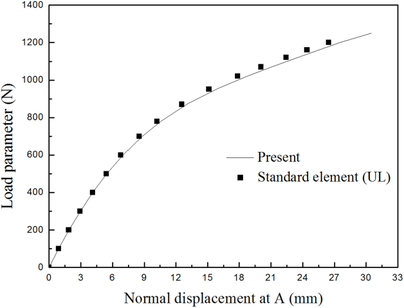
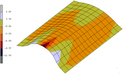
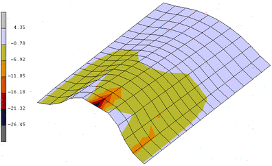
The normal displacement at A of the double-curved thin shell structure is compared with that of the standard 4-node thin shell element with 80×40 meshes in Figure 10, displacements of double-curved thin shell structure are obtained by load of 1.2 KN using standard element and present element, respectively, as shown in Figure 11. The relative error between present element with big grid and standard element with small grid is 4%, and the relative error between big grid and small grid models using standard element is 56.7%. The results showed that the present element is acceptable for the double-curved structure.
|
| Figure 10: Load-displacement curve of double-curved thin shell structure. |
style="padding:10x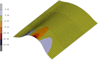
|
| (a) using standard element (80×40) |
|
| (b) using standard element (16×10) |
|
| (c) using present element (16×10) |
| Figure 11: Displacements of laminated thin cylinder by 1.2 KN. |
5. Conclusions
This paper mainly presented a highly efficient nonlinear computer modelling approach for laminated composite thin shell structures. The analysis method mainly includes 3 points:
- In the local coordinate, a simple and highly efficienct 4-node thin shell element formulation was presented, and the number of local degrees of freedom was reduced,
- A 4-node thin shell element CR formulation was established considering the element with large displacement,
- Finally, a highly efficienct element tangent stiffness matrix reduced from a 24×24 matrix to a 20×20 matrix was established to analyze laminated composite thin shell structures.
The test results presented in Section 4 show that all of the numerical results are the same, but the element presented in this paper is more efficient than the standard element. Especially, large deformation analysis of pinched cantilever cylinder (Example 4.2.2) and double-curved thin shell (Example 4.2.3) can be used to detect the results of geometric nonlinear analysis for other engineering structures. It is indicated that the present element is more effective since it can save much computation time, which is more applicable for engineering computation. The present work can be applied in designing and analyzing composite thin shell structure.
Acknowledgements
The work presented in this article was supported by the National Natural Science Foundation of China (Grant Nos. 51175424 & 51475369), the Basic Research Foundation of Northwestern Polytechnical University (Grant No. JC201238), and the Aeronautical Science Foundation of China (Grant No. 2016ZD53036).
References
[1] G.A. Wempner, Finite elements, finite rotation and small strains of flexible shells, International Journal of Solids and Structures, 5 (1969) 117-153.
[2] T. Belytschko, L. Schwer, Non-linear transient finite element analysis with convected co-ordinates, International Journal of Numerical Methods and Engineering, 7(9) (1973) 255-271.
[3] M.A. Crisfield, G.F. Moita, A unified co-rotational framework for solids, shells and beams, Solids Structures, 33 (1996) 2969-2992.
[4] K.M. Hsial, Y.L. Wen, A co-rotational formulation for thin-walled beams with monosymmetric open section, Computer Methods in Applied Mechanics and Engineering, 190 (2000) 1163-1185.
[5] Y.L. Wen, K.M. Hsial, Co-rotational formulation for geometric nonlinear analysis of doubly symmetric thin-walled beams, Computer Methods in Applied Mechanics and Engineering, 190 (2001) 6023-6052.
[6] C.L. Tham, Z. Zhang, A. Masud, An elasto-plastic damage model cast in a co-rotational kinematic framework for large deformation analysis of laminated composite shells, Computer Methods in Applied Mechanics and Engineering, 194 (2005) 2641-2660.
[7] N.D. Cortivo, C.A. Felippa, H. Bavestrello, W.T.M. Silva, Plastic buckling and collapse of thin shell structures, using layered plastic modeling and co-rotational ANDES finite elements, Computer Methods in Applied Mechanics and Engineering, 198 (2009) 785-798.
[8] B. Nour-Omid, C.C. Rankin, Finite rotation analysis and consistent linearization using projectors, Computer Methods in Applied Mechanics and Engineering, 93 (1991) 353-384.
[9] C. Pacoste, Co-rotational flat facet triangular elements for shell instability analysis, Computer Methods in Applied Mechanics and Engineering, 156 (1998) 75-110.
[10] A. Eriksson, C. Pacoste, Element formulation and numerical techniques for stability problems in shells, Computer Methods in Applied Mechanics and Engineering, 191 (2002) 3775-3810.
[11] J.M. Battini, A modified corotational framework for triangular shell elements, Computer Methods in Applied Mechanics and Engineering, 196 (2007) 1905-1914.
[12] K,D. Kim, G.R. Lomboy, S.C. Han, A co-rotational 8-node assumed strain shell element for postbuckling analysis of laminated composite plates and shells, Comput. Mech. 30(4) (2003) 330-42.
[13] K.D. Kim, C.S. Lee, S.C. Han, A 4-node co-rotational ANS shell element for laminated composite structures, Composite Structures, 80 (2007) 234-252.
[14] K.D. Kim, S.C. Han, S. Suthasupradit, Geometrically non-linear analysis of laminated composite structures using a 4-node co-rotational shell element with enhanced strains, International Journal of Non-Linear Mechanics, 42 (2007) 864-881.
[15] R. Alsafadie, M. Hjiaj, J.M. Battini, Corotational mixed finite element formulation for thin-walled beams with generic cross-section, Comput. Methods Appl. Mech. Engrg. 199 (2010) 3197-3212.
[16] F.S. Almeida, A.M. Awruch, Corotational nonlinear dynamic analysis of laminated composite shells, Finite Elements in Analysis and Design, 47 (2011) 1131-1145.
[17] T.N. Le, J.M. Battini, M.A. Hjiaj, Consistent 3D corotational beam element for nonlinear dynamic analysis of flexible structures, Comput. Methods Appl. Mech. Engrg. 269 (2014) 538-565.
[18] S. Faroughi, H.H. Khodaparast, M.I. Friswell, Non-linear dynamic analysis of tensegrity structures using a co-rotational method, International Journal of Non-Linear Mechanics, 69 (2015) 55-65.
[19] W. Wang, X.P. Zhu, Z. Zhou, J.B. Duan, A method for nonlinear aeroelasticity trim and stability analysis of very flexible aircraft based on co-rotational theory, Journal of Fluids and Structures, 62 (2016) 209-229.
[20] S. Cen, Y.Q. Long, Z.H. Yao, A new element based on the first-order shear deformation theory for the analysis of laminated composite plates, Engineering Mechanics, 1(19) (2002) 1-8.
[21] N.S. Pucha, J.N. Reddy, A mixed shear flexible finite element for the analysis of laminated plates, Comput. Meth. Appl. Mech. Eng. 44(2) (1984) 213-27.
[22] N A.K. oor, M.D. Mathers, Anisotropy and shear deformation in laminated composite plates, AIAA J, 14 (1975) 282-5.
[23] K.D. Lee, K W. anok-Nukulchai, A nine-node assumed strain finite element for large deformation analysis of laminated shells, Int. J. Num. Meth. Eng. 42 (1998) 777-798.
[24] P. Norachan, S. Suthasupradit, K.D. Kim, A co-rotational 8-node degenerated thin-walled element with assumed natural strain and enhanced assumed strain, Finite Elements in Analysis and Design, 50 (2012) 70-85.
Document information
Published on 03/01/18
Accepted on 05/06/17
Submitted on 02/03/17
Volume 34, Issue 1, 2018
DOI: 10.23967/j.rimni.2017.8.001
Licence: CC BY-NC-SA license
Share this document
Keywords
claim authorship
Are you one of the authors of this document?