Abstract
A computational procedure for analysis of the melting, burning and flame spread of polymers under fire conditions is presented. The method, termed Particle Finite Element Method (PFEM), combines concepts from particle-based techniques with those of the standard finite element method (FEM). The key feature of the PFEM is the use of an updated Lagrangian description to model the motion of nodes (particles) in the thermoplastic material. Nodes are viewed as material points which can freely move and even separate from the main analysis domain representing, for instance, the effect of melting and dripping of polymer particles. A mesh connects the nodes defining the discretized domain where the governing equations are solved using the FEM. An incremental iterative scheme for the solution of the nonlinear transient coupled thermal-flow problem, including radiation, loss of mass by gasification and combustion is used. Examples of the possibilities of the PFEM for the modelling and simulation of the melting, burning and flame spread of polymers under different fire conditions are described.
1 INTRODUCTION
Thermoplastic polymer objects, including mattresses, upholstered furniture, and molded objects such as electronic housings and automobile parts, respond to fire by burning, melting and dripping onto the surface below. The flow of polymer material affects heat and mass transport within the object, and the accumulating melt pool below the object extends the flaming zone and increases the overall rate of heat release [1]–[3]. The spread rate of the melt pool and its burning behavior (including whether it is even able to sustain ignition) are affected by the flooring material as well as by the properties of the melt.
Computer modeling and simulation of the burning, melting flow and flame spread of thermoplastics is extremely complex involving fluid flow, heat transfer, material degradation, flame chemistry, surface tension, and complex material properties [1]. In addition, the drastic changes in shape pose a severe challenge to traditional modelling methods [4].
The Particle Finite Element Method (PFEM) [5]–[13] is a powerful Lagrangian technique for modelling and analysis of complex multidisciplinary problems in fluid and solid mechanics involving coupled thermal effects, fragmentation and separation of fluid particles and fluid-structure interaction effects, among others. In the PFEM, the particles represent the nodes of a finite element mesh. The particles can move freely according to the velocity field, transporting their momentum and physical properties. A robust and efficient remeshing algorithm connects the nodes into a finite element grid for solution of the state variables in the new configuration. An advantage of the Lagrangian formulation in the PFEM is the elimination of the convective terms in the fluid flow and thermal equations, which favours the simplicity and symmetry of the formulation.
The PFEM has been used to solve a variety of free surface, fluid-structure interaction, and multiphase problems, including breaking waves in harbours, ship hydrodynamics, dam bursting and metal casting, among many others [5], [6]–[13]. Applications of the PFEM to modelling polymer melt flow are reported in [14]–[18], [30].
This paper describes the key aspects of the PFEM for analysis of the burning, melting flow and flame spread of polymer objects including loss of mass by gasification. The underlying ideas of the paper follow the original work of the authors in this field as presented in [15]–[17].
In the next section the basis of the PFEM is summarized. Then, the essential governing equations and an overview of the discretization procedure and the general solution scheme are given. The potential of the PFEM for the simulation of the burning, melt flow and spread of thermoplastic objects in fire is shown in examples of application for different heated samples.
2 THE PARTICLE FINITE ELEMENT METHOD. AN OVERVIEW
2.1 Basic steps of the PFEM
In the PFEM the analysis domain is modeled with an updated Lagrangian formulation [6,7,10,20]. The analysis domain can include the polymer and the surrounding air and fluid subdomains. All variables in the fluid and solid domains are assumed to be known in the current configuration at time . The new set of variables in both domains is sought in the next configuration at time . The finite element method (FEM) is used to solve the continuum equations in both domains. Hence a mesh discretizing these domains must be generated in order to solve the governing equations for both the fluid and solid problems in the standard FEM fashion [19,20]. To do this, the nodes discretizing the analysis domain are treated as material particles whose motion is tracked during the transient solution. This is useful to model the separation of particles from a solid domain, such as in the dripping of melt particles from a thermoplastic object, and to follow their subsequent motion as individual particles with a known density, an initial acceleration and velocity, and subject to gravity forces. Every node is a material point and hence is characterized by the density of the polymer material. The mass of a given domain is obtained by integrating the density at the different material points over the domain.
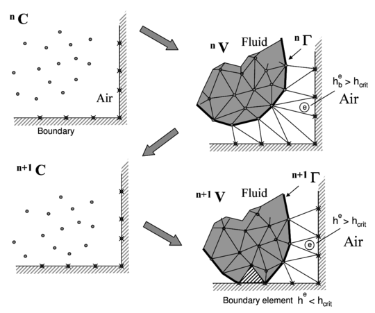
The way the PFEM solution process operates for the problems we are solving in this paper is schematically shown in Figure 1. The figure represents a polymer object hanging from a wall and subjected to an incoming heat flux acting at the lower part of the object.
The collection or cloud of nodes pertaining to the polymer analysis domain will be defined as (), the volume defining the thermoplastic analysis domain as (), and the mesh discretizing this domain as ().
A typical solution with the PFEM involves the following steps:
- The starting point at each time step is the cloud of points in the domain. For instance, and are the clouds at the initial time and at time , respectively (Figure 1).
- Identify the boundaries defining the analysis domain . This is an essential step as some boundaries, such as the free surface in the melting zone, may be severely distorted during the solution process. Some nodes may even separate from the boundary. The Alpha-Shape method [21] is used for the boundary definition. The analysis domain can include different subdomains formed by the polymer object and the dripping and spread zones (Figure 1).
- Discretize the analysis domain with a finite element mesh . In our work mesh generation scheme based on the extended Delaunay tessellation is typically used [7].
- Solve the coupled Lagrangian equations of motion for the polymer domains. Compute the relevant state variables at the next (updated) configuration for : velocities, strain rates, strains, pressure, viscous stresses and temperature in the polymer.
- Move the mesh nodes to a new position , where denotes the time . For the updated Lagrangian formulation discussed here, the nodes are moved according to the forces determined in step 4.
- Go back to step 1 and repeat the solution process for the next time step.
The quality of the numerical solution depends on the discretization chosen as in the standard FEM [19,20]. Adaptive mesh refinement techniques can be used to refine the mesh at the onset of the solution for each time step in order to improve the solution in zones where large motions of the fluid or the structure occur. Remeshing implies the introduction of new nodes in the mesh for which the state variables must be assigned via a projection method. The error introduced by the projection is corrected using an implicit algorithm which searches for a converged solution at the next configuration. In the examples shown in the paper the number of nodes during the transient solution has been kept constant.
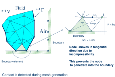
The contact between two solid interfaces is treated by introducing a layer of contact elements between the two interacting domains. This layer is automatically created during the mesh generation step by prescribing a minimum distance () between the two interacting boundaries that controls the accuracy of the contact model. If the distance is greater than the minimum value () then the generated elements are given the properties of air and treated as standard fluid elements, or else they are removed from the analysis domain (Figure 2). Otherwise, the elements are treated as contact elements where a relationship between the tangential and normal forces and the corresponding displacements (or velocities) is introduced so as to model frictional contact effects. This technique also prevents nodes in a fluid domain from crossing over rigid boundaries [6,7,11,12].
|
|
| Figure 2: Modelling of contact between the melting object and a fixed boundary using PFEM | |
2.2 Governing equations
It is assumed that the polymer melt flow is governed by the equations of a quasi-incompressible fluid with a temperature dependent viscosity. A quasi-rigid behaviour of the polymer at room temperature is reproduced by setting the viscosity to a sufficiently high value that the unheated polymer moves a negligible distance over the duration of the problem. As temperature increases in the polymer due to heat exposure, the viscosity decreases by several orders of magnitude as a function of temperature. This induces the melt and flow of the particles in the heated zone. The behaviour of the air surrounding the polymer, on the other hand, is also modelled with the equations for a quasi-incompressible fluid with a temperature dependent density (Boussinesq assumption). The key equations to be solved in the analysis domain (the polymer and the air), written in the Lagrangian frame of reference, are the following:
Momentum
|
|
(1) |
Mass balance
|
|
(2) |
Heat transport
|
|
(3) |
In the above equations is the velocity along the ith global (cartesian) axis, is the temperature, , , and are the density, the bulk modulus, the specific heat and the conductivity of the material along the ith coordinate direction, respectively, and are the body forces and the heat source per unit volume, respectively, and are the (Cauchy) stresses related to the velocities by the standard constitutive equation (for an incompressible Newtonian fluid)
|
|
(4) |
|
|
(5) |
In Eqs.(4) are the deviatoric stresses, is the pressure (assumed to be positive in tension), is the rate of deformation and is the viscosity. In the following we will assume and the viscosity to be a known function of temperature, i.e. .
As mentioned above, the dependence of the density of the air with the temperature follows the standard Boussinesq assumption as where is the density of the material at the reference temperature and is a dilatation parameter [3].
In Eqs. (1)–(3) means the material derivative of any variable with respect to time.
Indexes in Eqs.(1)-(4) range from , where is the number of space dimensions of the problem (i.e. for two-dimensional (2D) problems).
Eqs.(1)-(4) are completed with the standard boundary conditions of prescribed velocities and surface tractions in the mechanical problem and prescribed temperature and prescribed normal heat flux in the thermal problem [9,10,13,16,17]. For surfaces exposed to fire conditions, energy losses due to radiation and convection must be taken into account, and the thermal boundary condition is:
|
|
(6) |
with
|
|
(7) |
where is the derivative of temperature within the polymer object along the direction normal to the Neumann boundary , is the outgoing heat flux per unit area along the normal to the boundary surface, and the last two terms of Eqs.(2.2b) are the radiative and convective heat losses respectively, is the emissivity, is the Stefan-Boltzmann constant, and is the convection coefficient.
Eqs.(1)-(4) are the standard ones for modeling the deformation of viscoplastic materials using the so-called “flow approach” [22,23]. In our work we have limited the viscosity to be a non linear function of the temperature. Other dependencies of the viscosity with the shear rates and the yield stress, typical of the non-Newtonian flow of solids, can be easily incorporated in the model, thus broadening its applicability to other materials.
2.3 Discretization of the equations
A key problem in the numerical solution of Eqs.(1)-(4) is the satisfaction of the incompressibility condition (Eq.(2)). A number of procedures to solve this problem exist in the finite element literature [19]. In our approach, we use a stabilized formulation based on the so-called finite calculus procedure [13], [24]–[26]. The essence of this method is the solution of a modified mass balance equation that is written as
|
|
(8) |
where
|
|
(9) |
and is a stabilization parameter given by [25]
|
|
(10) |
In Eq.(10), is a characteristic length of each finite element (such as for 2D elements), and is the modulus of the velocity vector.
The variational equations for the whole problem are obtained by applying the standard Galerkin technique to the governing equations (1), (3) and (6) and the appropriate boundary conditions for the numerical and thermal problems [9,10,13,16,17].
We interpolate in the standard finite element fashion the set of problem variables. For 3D problems these are the three velocities , the pressure and the temperature . In our work we use an equal order linear interpolation for all variables over meshes of 3-noded triangles (in 2D) and 4-noded tetrahedra (in 3D) [7,11,12,13,19]. The resulting set of discretized equations has the following form
Momentum
|
|
(11) |
Mass balance
|
|
(12) |
Heat transfer
|
|
(13) |
In Eqs.(9)-(11) denotes nodal variables, . The different matrices and vectors are given in [12,13,16,17].
The solution in time of Eqs.(9)-(11) can be performed using any time integration scheme typical of the updated Lagrangian FEM. A basic algorithm following the conceptual process described in Section 2.1 is presented in Box I where denotes the values of the nodal variables at time and iteration . Note that the position of the analysis domain in the next equilibrium configuration at time is also an output of the solution, as is typical in updated Lagrangian methods. We recall the coupling of the flow and thermal equations via the dependence of the viscosity in the polymer and the density in the air with the temperature.
3 ACCOUNTING FOR GASIFICATION EFFECTS
The effect of gasification in the polymer can be introduced by adding a (nonlinear) energy loss term in the energy equation. This term represents the energy that migrates from the condensed phase object to the gas due to the gasification of a part of the material during the heating process. The volumetric gasification heat flux has the following form
|
|
(14) |
where is the enthalpy of vaporization,
|
|
(15) |
where expresses the (generally nonlinear) relation between the rate of volume variation due to the temperature, , and the temperature itself. In our work, the following Arrhenius function is chosen, consistent with single-step, first-order thermal decomposition kinetics [4]
|
|
(16) |
where is the pre-exponential function, is the activation energy, is the universal gas constant, and is the absolute temperature expressed in Kelvin.
Once the temperature field is known at each iteration of a time step, the rate of volume variation is fixed at every point of the mesh. This allows defining a continuum distribution of the term over the whole polymer domain.
The computed mass loss rate has to be included in the problem to ensure that the volume variation of the sample is correctly modeled. The approach is thus to solve the momentum and heat transfer equations, prescribing as constraints the local rate of volume variation and the gasification heat flux.
From a practical point of view this simply implies adding the gasification heat flux as an additional volumetric heat source term in vector in the heat transfer equations and adding the volumetric deformation rate into the stabilized mass balance equation (6) as [16]
|
|
(17) |
The new discretized mass balance equation is
|
|
(18) |
where with is the forcing term contributed by the gasification heat flux.
4 ACCOUNTING FOR RADIATION EFFECTS IN THE AIR
Radiation effects can be accounted for in the air by modifying the heat source in Eq.(3) as
|
|
(19) |
where are the component of the radiative heat flux and is the standard heat source excluding radiation effects.
For a nongray medium the radiative term in Eq.(17) is computed as
|
|
(20) |
where is the spectral intensity at time t, in position , within wavelength and propagating along direction with speed [27]. The conservation equation of radiant transfer, which describes the behavior of the spectral intensity, is written as
|
|
(21) |
with being the speed of light. For most of engineering applications, is so large compared to local time and length scales that with sufficient accuracy the unsteady term in (21) may be omitted and the radiation transfer equation may be considered in the quasi-steady limit. The source term on the right-hand side of Eq. (21) can be written as
|
|
(22) |
where is the absorption coefficient, is the scattering coefficient, is the Planck function and is the phase function [27]. Both absorption and scattering coefficients are functions of wavelength, chemical composition of the medium, temperature and pressure. Equation (21) must be subject to boundary conditions into the inflow boundary of the type
|
|
(23) |
where is the unit normal vector pointing outwards at , is the diffuse reflection wall coefficient, is the emissive wall coefficient, and the wall temperature at . To compute the reflected intensity we need to integrate over all the outgoing directions at a boundary point . In our work, the gray gas simplifying assumption is considered, which implies that absorption and emission coefficients are independent of the wavelength of radiation. Equations (20-21) are simplified, if scattering is neglected, to
|
|
(24) |
and
|
|
(25) |
with the boundary condition
|
|
(26) |
The radiation transport equation (25) involves not only spatial discretization but also the angular integration over the solid angle. To solve this equation numerically, both the spatial domain and the angular domain must be discretized. The angular domain at any spatial location is divided into a finite number of discrete, non-overlapping solid angles, using the quadrature sets introduced by Lathrop and Carlson [28]. The system of equations arising from the monochromatic radiative transfer equation (25) are discretized in space by the finite element method can be written in matrix form as a system of convection reaction equations in the following form:
|
|
(27) |
for a set of discrete directions (). Once this system is solved, the radiative heat flux through the interface is evaluated as
|
|
(28) |
For the sake of simplicity we have omitted here the details about the stabilization of the governing equations. In the present work, the GLS method was implemented [17].
5 A SIMPLE MODEL FOR THE BURNING OF POLYMERS
In our work we have simulated the burning of polymers with PFEM using a simplified phenomenological combustion model.
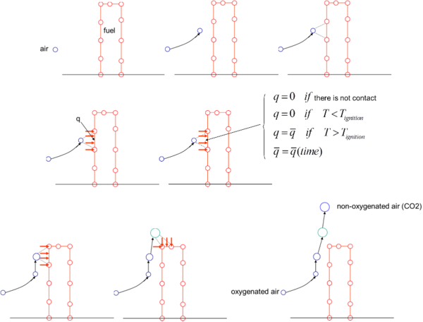
Air particles are assumed to be transported by the convective flow generated by the temperature gradient in the air domain. Once an air particle is adjacent to the polymer surface, a transfer of heat between the particle and the polymer surface is activated during a prescribed time. Once this time is elapsed, air particles are transformed into CO particles that move away from the polymer due to the convective flow.
Mass loss effects due to gasification can be accounted for in the ignited polymer following the Arrhenius model described in Section 3.
Melt flow and dripping effects are modelled using the PFEM technology as explained in Section 2.1.
Figure 3 shows a schematic representation of this simple and effective combustion model.
Extension of the combustion model to account for the competing effect of charring, flame inhibition, gasification and melt flow/dripping are under development by the authors.
6 NUMERICAL EXAMPLES
The examples were run in the PFIRE code in which the formulation described above has been implemented using the Kratos software platform [29] (www.cimne.com/kratos).
6.1 Melting and flow of a rectangular slab
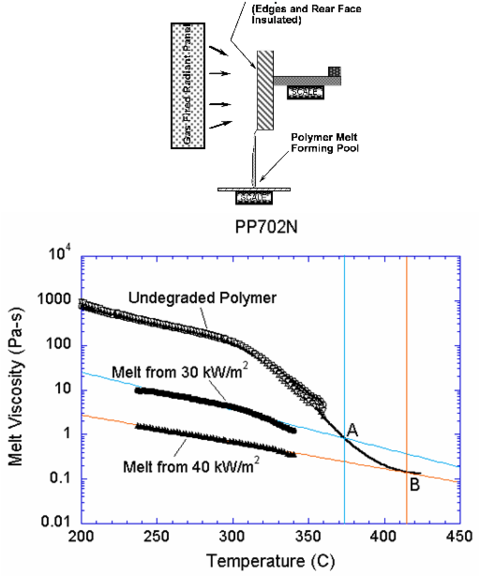
In this example, the PFEM is used to simulate an experiment performed at NIST in which a slab of PP702N polypropylene material is mounted vertically and exposed to uniform radiant heating on one face. Degradation of the polymer decreases its viscosity by several orders of magnitude and produces fuel gases. Polymer melt is captured by a pan below the sample.
A schematic of the apparatus used in the experiments is shown in Figure 4. The sample is insulated on its lateral and rear faces. The melt flows down the heated face of the sample and drips onto a surface below. A load cell monitors the mass of polymer remaining in the sample, and a laboratory balance measures the mass of polymer falling onto the catch surface. Details of the experimental setup can be found in [4,14,15,16]. The height and thickness of the sample in our analysis were 25cm and 5cm, respectively following the data of the experimental tests [31]. The effect of the air surrounding the polymer is neglected in this example.
| Parameter | Symbol | Value | Units |
| Density | 900 | kg/m | |
| Thermal conductivity | 0.25 | W/m-K | |
| Specific heat | 2400 | J/kg-K | |
| Reference temperature | 298 | K | |
| Emissivity | 1.0 | - | |
| Convective heat transfer coefficient | 8 | W/m-K | |
| Heat of vaporization | J/kg | ||
| Pre-exponential function | s | ||
| Activation energy divided by universal | |||
| gas constant | 24400 | K | |
| Stefan-Boltzmann constant | 5.67 | W/m- K |
The 2D computational representation of this problem is a rectangle of polymer material with steady heat flux applied to one side and adiabatic and no-slip conditions applied to the opposite side, top and bottom. The heated side is defined as a free surface, and is subject to radiative and convective losses. Gasification is not considered in this first example. Material properties except for viscosity are taken as constant, with values as given in Table 6.1. The temperature dependence of viscosity is shown in Figure 4. For details see [16,31].
The problem was solved with an initial PFEM mesh of 2818 three-noded triangular elements discretizing the polymer. No nodes were added during the course of the analysis in this and all the other examples shown in the paper.
The addition of a catch pan to capture the dripping polymer melt tests the ability of the PFEM model to recover mass when a falling particle or set of particles reaches the catch surface. Heat flux was only applied to free surfaces above the midpoint between the catch pan and the base of the sample. However, every free surface is subject to radiative and convective heat losses. The problem was studied for three heat flux levels of 20, 30 and 40 kW/m. The catch pan is set to 250 C, a temperature that is high enough to keep the melt fluid [31].
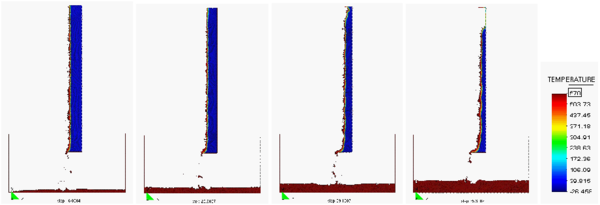
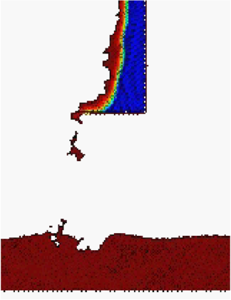
Figure 5a shows four snapshots of the time evolution of the melt flow into the catch pan using the finer grid and a heat flux level of 20 kW/m.
|
| Figure 5: Evolution of the melt flow into the catch pan at t = 400s, 550s, 700s and 1000s |
|
|
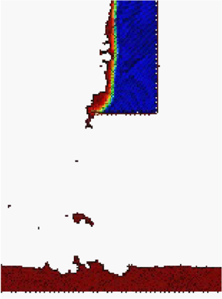
| Figure 6: Detail of the flow of the melt as it drips into the pan at and 1000s | |
Figure 5 shows a detail of the flow of the melt as it drips into the pan at two different times.
Figure 6 presents a detail of the melt flow into the catch pan at times s and 1000s. PFEM results for the spread of the flame on the catch pan for different inclinations of the catch pan surface can be found in [16,30]
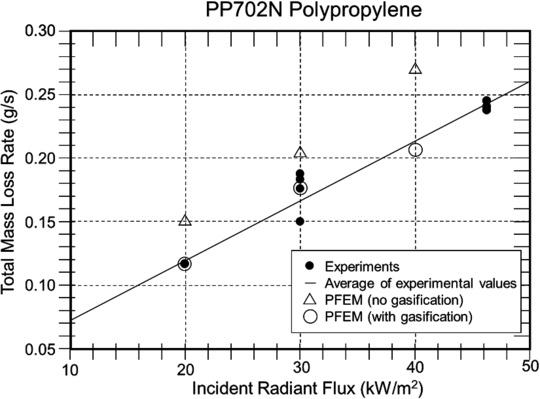
Figure 7 compares the mass loss rate of the quasi-steady period with that obtained from experiments at three levels of heat flux performed at NIST [31]. The mass loss rate follows the same trend, although the values are about 25% higher than the experimental data. Note that this solution includes only melt flow in response to heating at a steady heat flux with radiative and convective losses.
6.2 Inclusion of gasification effects
The same problem of previous section was solved next including gasification effects. The parameters in the gasification heat flux model chosen for the computations (Eqs.(12)–(16)) are given in Table 1.
The general trend of the numerical results including gasification is not very different from the results shown in Figures 5 and 6. Gasification effects however have an influence on the mass loss rate.
Results for the mass loss rate including gasification are represented by circles in Figure 7. The computational results fall within experimental error for the range of heat fluxes considered. This shows the importance of accounting for gasification effects in this type of problem. The decrease in mass loss rate when gasification is added to flow demonstrates two competing effects: the loss of additional mass as gas is released and the cooling caused by the endothermic process of polymer decomposition.
Note that this model is not yet complete, since phenomena such as in-depth absorption, the melting of the crystalline fraction of the polymer, and the temperature dependence of other material properties are not yet included. However, these phenomena are not difficult to add to the model and will be included in future development.
The solution of this melt flow problem took 1 CPU hour in a standard Pentium 4 PC. Further information on the PFEM solution of this problem can be found in [11,30].
The PFEM solution of the same problem accounting for convection and radiation effects in the surrounding air have been reported in [17].
|
| Figure 7: Comparison of PFEM results to experiments for mass loss rate as a function of incident radiant flux |
6.3 3D analysis of the melting of a polymer cover for three cables
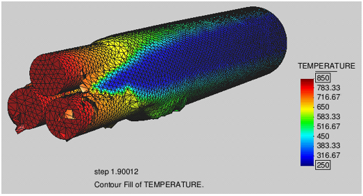
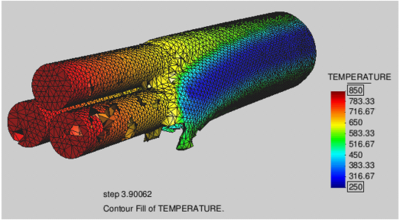
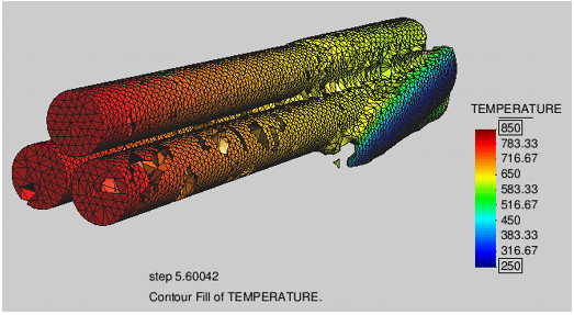
The ability of the PFEM to solve 3D polymer melt flow problems was tested in the analysis of the melting and dripping of a polymer cover protecting three cables under the action of an external heat source. The initial discretization has some 25000 nodes and 100000 four-noded tetrahedra. The runtime for this problem was slightly over 4 hours in a standard Pentium 4 PC. The shape of the polymer cover and the temperature field at different times after heating begins are displayed in Figure 8. Once again the effect of the surrounding air was not taken into account in the analysis.
Although the resolution of this problem is not fine enough to achieve high accuracy, the qualitative and the ability to carry out this problem in a reasonable amount of time indicate that the PFEM can be used to model melt flow, dripping and spread of complex 3D polymer geometries.
6.4 Burning of a rectangular polymer in a closed cavity
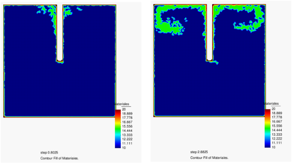
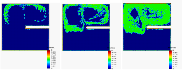
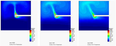
Figure 9a shows the 2D PFEM results for the analysis of the burning of a rectangular polymer object in a closed square cavity. We note that the shape of the polymer has been artificially kept the same during the whole combustion process. The flame was initiated by a high temperature of 1500 at the left-end of the polymer. Figure 9a shows the evolution of CO in the cavity as the burning progresses. Clearly, as the cavity is closed, the flame extinguishes when the amount of CO filling the cavity prevents oxygen to reach the polymer tip. The evolution of the flame at the onset and final stages of the burning is shown in Figure 9b.
|
|
| (a) | (b) |
| Figure 9: Burning of a rectangular thermoplastic object in a closed cavity. (a) Evolution of CO filling the cavity until the flame extinguishes. (b) Evolution of the flame for three time instants corresponding to the CO levels of Figure 9a | |
6.5 Burning of a candle
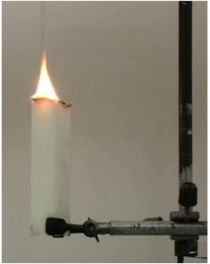
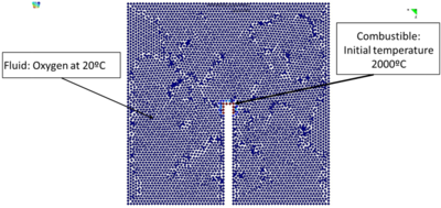
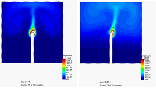
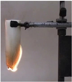
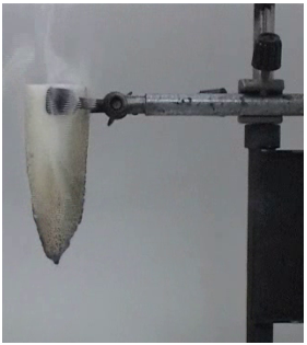
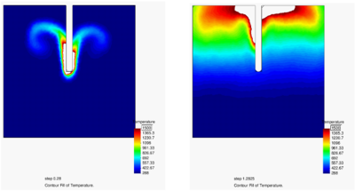
Figures 10 and 11 show the 2D FPEM results for the analysis of the burning of a polymer candle for which experimental results are available. The geometry of the candle is assumed to be constant during the burning, for simplicity. PFEM results in Figure 10 show that when the candle burns in the standard manner (with the flame on the top) the burning process evolves in time as expected. However, if the candle is ignited from the bottom, the flame extinguishes after a few seconds due to the convective effects in the air surrounding the flame. This result is clearly shown in Figure 11 where the experimental results for the onset of the flame and its extinction are also shown.
We note that the PFEM analysis has been carried out with the candle placed in a closed cavity. Hence, we can expect that the accumulation of CO in the cavity contributes to extinguish the flame faster than when the flame is in an open air situation. In any case the PFEM results reproduce the two burning escenarios in a qualitatively realistic manner.
One more, the geometry of the flame was assumed to be constant during the burning process, for simplicity.
6.6 Burning and melting of a rectangular polymer
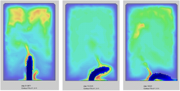
The final example is the 2D PFEM analysis of the burning of a rectangular polymer object in a closed rectangular cavity. The change of the geometry of the polymer due to gasification and melting during burning was taken into account in this case.
Figure 12 shows three instants of the evolution of the polymer shape as it burns, melts and drips into the base of the cavity.
This simple example shows the potential of the PFEM for the analysis of the burning of polymer objects accounting for the change in their shape due to combustion, melting and dripping.
|
| Figure 12: Burning of a rectangular thermoplastic object in a close cavity. Evolution of the burning, melting and dripping process for three instants of time |
7 CONCLUDING REMARKS
The PFEM is a powerful technique to model the combustion, melting flow and flame spread of thermoplastic objects in fire situations. The method allows to track the motion of the polymer particles as they burn, melt, flow over the surface of the object and fall and spread on the underlying floor. The PFEM can also predict the spread of the flame in a floor of arbitrary geometry for different ambient temperature conditions and effect of gasification, in-depth absorption and radiation problems.
The examples presented have shown the potential of the PFEM to model the drastic change of shape of polymer objects as they burn, melt, drip and spread in the floor, including self-contact situations.
ACKNOWLEDGMENTS
The authors thank Dr. Katheryn Butler from NIST for providing advice and access to experimental results for the 2D rectangular slab problem [31].
Thanks are given to Dr. P. Dadvand for his advice and support in the development of the PFIRE code using the Kratos software platform [29].
This work was carried out with partial support of the SAFECON and REALTIME projects of the ERC programme of the European Commission and the HFLUIDS project of the National RTD Programme of Spain.
BIBLIOGRAPHY
[1] Zhang J, Shields TJ, Silcock GWH. Effect of melting behaviour on flame spread of thermoplastics. Fire & Materials 1997; 21(1):1–6.
[2] Fleischmann CM, Hill GR. Burning behaviour of upholstered furniture. Interflam 2004; 907–916.
[3] Sherratt J, Drysdale D. The effect of the melt-flow process on the fire behaviour of thermoplastics. Interflam 2001; 149–159.
[4] Butler KM, Ohlemiller TJ, Linteris GT. A progress report on numerical modeling of experimental polymer melt flow behavior. Interflam 2004; pp. 937–948.
[5] Idelsohn SR, Oñate E, Calvo N, Del Pin F. The meshless finite element method. International Journal for Numerical Methods in Engineering 2003; 58(6): 893–912.
[6] Idelsohn SR, Oñate E, Del Pin F. The particle finite element method: a powerful tool to solve incompressible flows with free-surfaces and breaking waves. International Journal for Numerical Methods in Engineering 2004; 61:964–989.
[7] Oñate E, Idelsohn SR, Del Pin F, Aubry R. The particle finite element method. An overview. International Journal of Computational Methods 2004; 1(2):267–307.
[8] Aubry R, Idelsohn SR, Oñate E. Particle finite element method in fluid-mechanics including thermal convection-diffusion. Computers and Structures 2005; 83(17-18):1459–1475.
[9] Aubry R, Idelsohn SR, Oñate E. Fractional step like schemes for free surface problems with thermal coupling using the Lagrangian PFEM. Computational Mechanics 2006; 38(4-5):294–309.
[10] Oñate E, Idelsohn SR, Celigueta MA, Rossi R. Advances in the particle finite element method for the analysis of fluid-multibody interaction and bed erosion in free surface flows. Computer Methods in Applied Mechanics and Engineering 2008; 197(19-20):1777–1800.
[11] Oñate E, Celigueta MA, Idelsohn SR. Possibilities of the particle finite element method for fluid–soil–structure interaction problems. Computational Mechanics 2011; 48(3):307–318.
[12] Oñate E, Franci A, Carbonell JM. A FIC-based stabilized Lagrangian formulation with negligible mass losses for incompressible fluids. Application to free-surface flows using PFEM. Publication CIMNE, No. PI394 2013. Submitted to Int. J. Num. Meth. Fluids.
[13] Idelsohn SR, Mier-Torrecilla M, Oñate E. Multi-fluid flows with the Particle Finite Element Method. Comput. Methods Appl. Mech. Engrg 2009; 198:2750–2767.
[14] Butler KM, Oñate E, Idelsohn SR, Rossi R. Modeling polymer melt flow using the particle finite element method. 11th International Interflam Conference (Interflam'07), September 3–5 2007, London, England, Volume 2, pp. 929–940.
[15] Rossi R, Butler KM, Oñate E, Idelsohn SR. Modeling polymer melt flow using the Particle Finite Element Method. Advanced Research Workshop on Fire Computer Modeling, Gijón, Spain, October 18-20, 2007.
[16] Oñate E, Rossi R, Idelsohn SR, Butler K. Melting and spread of polymers in fire with the particle finite element method. Int. J. Numer. Meth. Engng. 2010; 81(8):1046-1072.
[17] Marti J, Ryzhakov P, Idelsohn SR, Oñate E. Combined Eulerian-PFEM approach for analysis of polymers in fire situations. Int. J. Numer. Meth. Engng. 2012; 92:782–801.
[18] Kempel F, Schartel B, Marti JM, Bulter KM, Rossi R, Idelsohn SR, Oñate E, Hofmann A. Modelling the vertical UL 94 test: Competition and collaboration between melt dripping, gasification and combustion. Submitted to Fire and Material, 2012.
[19] Zienkiewicz OC, Taylor RL, Nithiarasu N. The Finite Element Method. Vol. 3 Fluid Mechanics, Elsevier, 2005.
[20] Zienkiewicz OC, Taylor RL, The Finite Element Method. Vol. 2 Solid Structural Mechanics, Elsevier, 2005.
[21] Edelsbrunner H, Mucke EP. Three dimensional alpha shapes. ACM Trans. Graphics 1999; 13:43–72.
[22] Zienkiewicz OC, Jain P C, Oñate E. Flow of solids during forming and extrusion: Some aspects of numerical solutions. International Journal of Solids and Structures 1978; 14:15–38.
[23] Zienkiewicz OC, Oñate E, Heinrich JC. A general formulation for the coupled thermal flow of metals using finite elements. International Journal for Numerical Methods in Engineering 1981; 17:1497–1514.
[24] Oñate E. Derivation of stabilized equations for numerical solution of advective-diffusive transport and fluid flow problems. Computer Methods in Applied Mechanics and Engineering 1998; 151:233-265.
[25] Oñate E. A stabilized finite element method for incompressible viscous flows using a finite increment calculus formulation. Computer Methods in Applied Mechanics and Engineering 2000; 182(3-4):355-370.
[26] Oñate E. Possibilities of finite calculus in computational mechanics. International Journal for Numerical Methods in Engineering 2004; 60(1):255–281.
[27] Modest M.F., Radiative heat transfer. Academic Press, 2003.
[28] Lathrop K.D. and B.G. Carlson. Discrete-ordinates angular quadrature of the neutron transport equation. Technical Information Series Report LASL-3186, Los Alamos Scientific Laboratory, 1965.
[29] Dadvand P, Rossi R, Oñate E. An object-oriented environment for developing finite element codes for multi-disciplinary applications. Archives of Computational Methods in Engineering 2010; 17:253–297.
[30] Butler KM. A model of melting and dripping thermoplastic objects in fire. Fire and Materials 2009, San Francisco, USA, January 26–28, 2009, pp. 341–352.
[31] Ohlemiller TJ, Shields JR. Aspects of the Fire Behavior of Thermoplastic Materials. NIST Technical Note 1493 2008.
Document information
Published on 01/01/2016
Licence: CC BY-NC-SA license
Share this document
claim authorship
Are you one of the authors of this document?


