1 Introduction
Fiber reinforced polymer (FRP) composites, with their high strength-to-weight ratio, high stiffness, fatigue and corrosion resistance etc., are widely used in applications such as aerospace, flywheels, ultralight vehicles and construction reinforcement etc.
However, interlaminar properties in advanced laminated composites severely limit the overall performance of these systems, particularly problematic are delaminations caused by many sources including transverse impact. Nano-scale reinforcement using nanofillers like carbon nanotubes (CNTs) in between the plies of a composite offers the opportunity to reinforce the interlaminar bonding with minimal weight penalty and effectively avoids reductions in in-plane properties. These nanocomposites exhibit remarkable structural performance and multifunctional properties by synergistically combining the characteristics of both components if proper structural and interfacial organization is achieved. Interlaminar strength is thus increased by the reinforcement in the z-direction, and crack growth is forestalled by a “pinning” mechanism that occurs between the plies [1-3].
In this work, macroscopic CNT veils with controlled nano-meso structure were drawn from the gas-phase using a semi-industrial process. These veils, then, can be easily deposited in between the primary carbon fabric layers before infusion. Thus, the viscosity of the composite matrix is not affected. Interlaminar fracture toughness (ILFT) of the resulting composites was determined in Mode-I (opening mode) conditions. What is more, crack propagation and interlaminar toughening mechanisms were systematically analyzed by means of optical microscope and Raman analysis. The results show that the degree of compaction of the starting CNT fiber veil is the dominant factor with respect to the critical strain energy release rate in mode-I delamination (GIC).
2 Experimental
2.1 Materials
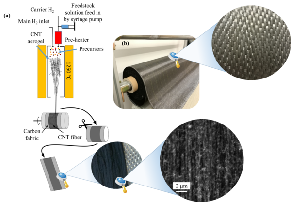
Macroscopic veils of CNT fibers were synthesized by the direct spinning process, whereby a CNT web (aerogel) is directly drawn from the gas-phase during growth of CNTs by floating catalyst chemical vapor deposition (FCCVD [4]). As displayed in Figure 1a, the CNT fibers were continuously drawn out at the exit of the furnace and directly deposited onto the surface of a piece of carbon fabric. The carbon fabrics used in this study was the G0926 Hexcel woven fabric with a weave style of 5H satin (Figure 1b). DERAKANE 8084 was chosen as matrix which is an elastomer-modified bisphenol-A epoxy vinyl ester resin for structural applications and provided by Ashland Inc. Both the MEKP hardener and Cobalt octoate catalyst were available from Plastiform S.A.
2.2 Laminate preparation
The interleaves were produced by winding continuous fiber of CNTs directly onto CF fabric wrapped around a cylindrical winder (Figure 1a). A optimized VARTM method was used for manufacturing the target laminate [5]. Before starting infusion, resin was degassed for 10 minutes in a vacuum chamber under a vacuum degree of -0.88 bar. After completing the infusion process, the laminate was cured at room temperature (RT) for 24 hours, followed by a post curing step at 60℃ for 2 hours. Note that CNT-interleaved composites and baseline (without CNT) were manufactured in a same batch to minimize the influence of other uncontrollable factors on the testing results.
2.3 Characterization
The DCB tests were carried out in accordance with ASTM Standard D5528-01 [6], which specifies either hinges or end blocks for load introduction. Measurements were conducted in a standard testing machine (Instron 3384) at loading rate of 1 mm/min. Force was detected by utilizing a 500 N load cell and the displacement recorded by load frame, both of which were digitally stored by the machine. Crack growth was visually observed every millimeter and listed in an experimental sheet. Scanning electron microscope (SEM) and optical microscope were used to investigate the morphology of CNT fiber veils as well as the fracture surfaces of the laminates. Raman spectroscopy (530 nm wavelength) analysis was also performed to identify constituents at the fracture surface.
3 Results and Discussion
3.1 Load–extension curves, R-curves and GIC
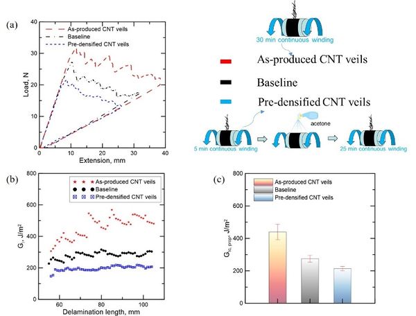
Pristine and CNT veil-interleaved woven composites were produced with the 5H Satin weave fabrics as described and tested as discussed above. Though the load-extension curves of woven composites always display stick-slip crack propagation behavior, as shown in Figure 2, the data can still be utilized to generate R-curves [7].
There is moderate fiber bridging in the pure woven laminates, resulting in a relatively flat R-curve, which is in line with similar systems [8]. For the control samples without CNT veils, the difference between GIC,ini and GIC,prop is marginal, especially when compared with the differences observed in unidirectional fiber reinforced composites [8, 9].
Incorporation of the low-density, as-produced CNT veils, produces a sharp rise in the R-curve, with the propagation value of fracture toughness (GIC, prop) increasing up to ~50% compared with the initiation value (GIC, ini) due to a hierarchical fiber-bridging toughening mechanism. Remarkably, the average values of GIC, prop for as-produced CNT samples are 60% higher compared with the corresponding value of the baseline material. In contrast, the densified veils produced a 28.4% decrease of GIC, prop. This layer functioned essentially as a defect that weakened the interlaminar region and did not produce any fiber-bridging, thus effectively reducing the fracture toughness of resulting laminate.
Figure 2. Representative Load-extension curves (a) and R-curves (b) of specimens with and without CNT veils; (c) comparison of Mode I interlaminar fracture toughness for CNT-interleaved composites (as-produced and pre-densified CNT veils) and baseline (without CNT veils).
3.2 Crack propagation
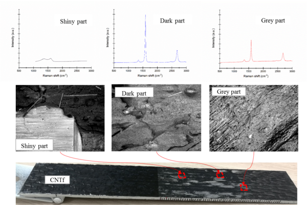
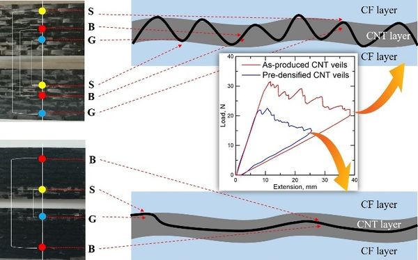
Toughening effect, to a considerable degree, depends on crack behavior. Several surface analysis technologies were used in order to get a deeper insight into the crack initiation and propagation behaviors as well as the corresponding toughening mechanisms. As represented in Figure 3, three distinct regions were observed on the whole fracture surface, named as shiny (S), grey (G) and dark (D) part respectively. The composition of the different regions could be readily determined from their Raman spectra. Considering the low D/G ratio and sharp G band lineshape, grey and dark regions can be easily recognized as CNT-rich regions, whereas the shiny areas, with broad D and G bands of similar intensity, correspond to carbon fiber. Thus, the Raman data enable to identify different colors on the fracture surface to different layers of the composite and ultimately, to different interfaces: S/G represent CF/CNT veil interfaces and B/B represent CNT veil/CNT veil interfaces.
Above prerequisites together with a comparative analysis of corresponding parts of opened sample enable us to image, readily and precisely, how cracks initiate and propagate during the opening test, as shown in Figure 4. It manifested that delaminations in CNT-toughened sample with poor fracture toughness progress almost exclusively within nano-toughened interlayer. The energy required for such failure will depend on the adhesion of the CNT with the matrix resin, however, this kind of bonding in this sample was proved to be weak due to the poor infiltration of resin among CNTs. The delaminations in sample with excellent energy-consuming behavior show regular crossings of the interlaminar region through the nano-toughened interlayer. This saw-like interlaminar crossings result in a crack not only through the nanotoughened epoxy (causing nano-scale bridgings), but also entangled with woven fabric (triggering carbon fiber bridgings), which significantly enhances the interlaminar fracture toughness.
4 Conclusions
A facile and scalable infusion protocol was successfully developed to make CNT veil/CF/epoxy hybrids, leading to void-free laminates manufactured by VARTM without utilizing additional expensive or complex techniques.
The results demonstrated that the degree of densification of the CNT veil exerts a profound influence on the resulting interlaminar properties. Low-density “fluffy” CNT veils consistently led to CFRP laminates with as much as 60% enhancement of GIC, prop. In contrast, integrating densified CNT veils deteriorated their interlaminar mechanical performances.
A new methodology combining Raman analysis and surface observation was proposed to study the crack propagation behavior, which was proven to be feasible and can determine the failure position, precisely and readily. The analysis results showed that interlaminar crossing play a paramount role in toughening mechanism.
Acknowledgements
The authors are grateful for generous financial support provided by the European Union Seventh Framework Program under grant agreement 678565 (ERC-STEM), the MINECO (RyC-2014-15115, MAT2015-64167-C2-1-R), the ESTENEA funded by AIRBUS Operations S.L. and CDTI (CIEN 2014 program), and the Cost Action CA15107 (MultiComp). Yunfu Ou appreciates the financial support from the China Scholarship Council [grant number 201606130061].
References
[1] Guzman de Villoria R, Hallander P, Ydrefors L, Nordin P, Wardle B. In-plane strength enhancement of laminated composites via aligned carbon nanotube interlaminar reinforcement. Compos Sci Technol 2016;133:33-39.
[2] Mikhalchan A, Gspann T, Windle A. Aligned carbon nanotube–epoxy composites: the effect of nanotube organization on strength, stiffness, and toughness. J Mater Sci 2016;51(22):10005-10025.
[3] Wicks SS, de Villoria RG, Wardle BL. Interlaminar and intralaminar reinforcement of composite laminates with aligned carbon nanotubes. Compos Sci Technol 2010;70(1):20-28.
[4] Li Y-L, Kinloch IA, Windle AH. Direct spinning of carbon nanotube fibers from chemical vapor deposition synthesis. Science 2004;304(5668):276-278.
[5] Ou Y, González C, Vilatela JJ. Interlaminar toughening in structural carbon fiber/epoxy composites interleaved with carbon nanotube veils. Composites Part A 2019;Under review.
[6] ASTM Standard D5528, Standard Test Method for the Mode I Interlaminar Fracture Toughness of Unidirectional Fiber-Reinforced Polymer Matrix Composites, 2013.
[7] Gill AF, Robinson P, Pinho S. Effect of variation in fibre volume fraction on modes I and II delamination behaviour of 5HS woven composites manufactured by RTM. Compos Sci Technol 2009;69(14):2368-2375.
[8] Daelemans L, van der Heijden S, De Baere I, Rahier H, Van Paepegem W, De Clerck K. Nanofibre bridging as a toughening mechanism in carbon/epoxy composite laminates interleaved with electrospun polyamide nanofibrous veils. Compos Sci Technol 2015;117:244-256.
[9] Narducci F, Lee K-Y, Pinho S. Interface micro-texturing for interlaminar toughness tailoring: a film-casting technique. Compos Sci Technol 2018;156:203-214.
Document information
Published on 01/06/22
Accepted on 01/06/22
Submitted on 28/05/22
Volume 04 - Comunicaciones Matcomp19 (2020), Issue Núm. 1 - Avances en Materiales Compuestos. Nuevos Campos de Aplicación., 2022
DOI: 10.23967/r.matcomp.2022.06.014
Licence: Other
Share this document
Keywords
claim authorship
Are you one of the authors of this document?


