1 Introduction
Composite materials were introduced in the civil aeronautic industry in the late 1980s. Airbus Group was the first company to implement primary structures made of composite materials in its aircrafts. The said structures were the vertical and the horizontal tail planes, keel beams and rear pressure bulkheads.
Based on the excellent performance of the composite structures, Airbus decided to manufacture the central wing box and rear fuselage in composite for the A380 aircraft.
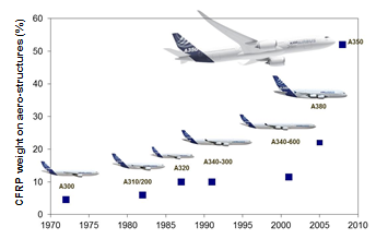
For the new A350 XWB Airbus went one step beyond, using carbon fiber reinforced polymers (CFRP) for the manufacture of the wing boxes and the fuselage achieving more than 50% of the structure in terms of weight made with composite materials, (see Figure 1, [1]).
Using these types of materials, the corrosion and fatigue related maintenance tasks are reduced by 60%.
The application of bonded repairs in composite components is well established and spread in the aeronautical industry, specially for minor accidental damages during the operational life of the aircraft and for rework of small defects during the manufacturing process. The frequency of minor accidental damages during the operational life of the aircraft is high and their repairs impact significantly the maintenance costs.
Severe damages, if less frequent, have also an important impact in the maintenance costs as they might imply to stop the normal aircraft operation and require costly and time-consuming repairs. The application of bolted metallic or composite patches is one way of repairing severe damages in highly loaded primary CFRP structures. The use of this technology implies high energy consumption in machining, drilling and riveting, the use of autoclave when composite repair doublers are used and additional materials and operations, such as metal treatments, priming, sealing, painting. Alternatively, bonded repairs can be used, which present many advantages over mechanical fastening including the potential for improved strength and fatigue resistance and minimisation of the need to further damage the structure by the formation of fastener holes [2].
The inability of NDI techniques to detect efficiently contaminants in the repair area and to assess the bond quality and strength impose limits in the applicability of bonded repairs and restricts the damage sizes to those where the repaired structure can sustain limit load with the patch off [3, 4]. Limit load (LL) is defined as the maximum load that an aircraft is expected to experience at any point during its service life. Even though there are many damage scenarios that can be effectively repaired by bonded patches which restore the full component capability and have no impact in the aerodynamic behaviour.
Restoration of full strength, stiffness and damage tolerance relies in the use of proper repair design and repair materials and processes. The use of original production materials is usually prevented for in-service repairs, as they require autoclave curing to achieve their best performance, which is not suitable for wing, fuselage, stabilizers or other primary structures. Even for components that can be easily disassembled, like doors, access panels, fairings, etc., the use of original production materials is also not a common practice due again to the necessity of using the autoclave with the appropriate tooling to avoid component deformation and to the hazards associated to the heating of the component at high temperature.
Materials specially dedicated to repair purposes have been therefore developed by the material suppliers and all have in common the suitability to be cured at temperatures in the range of 120ºC - 140ºC and to achieve good properties (low porosity) when cured only under vacuum pressure.
Besides the availability of these types of materials, the additional essential requisite for the implementation of out of autoclave bonded repairs is the exhaustive knowledge of the repair process and its limits.
Laboratory trials can replace trials on the parts but only if the setup reproduces conservatively the actual repair conditions. Ultimate process validation must anyway be performed in the assembled component or aircraft.
Confidence in the ability and robustness of the candidate repair system and defined process to behave well and reproducibly in a variety of repair scenarios is one of the expected outputs of these trials. The processing window should not be too narrow and should be realistic and adapted to field conditions.
In this paper the challenges of the development of a suitable and robust out of autoclave structural bonded repair system and process for highly loaded CFRP components are described.
2 Project development
The development project was planned as a set of complementary tests and trials on the candidate materials (carbon epoxy unidirectional repair prepreg and adhesive film, both intended for out of autoclave cure) and the recommended repair process to prove their suitability for the actual repair conditions in a wide variety of damage scenarios, to determine the key process parameters and their limits and to obtain the physical and mechanical properties of the repair patch and bonded joint.
Laboratory tests produced the key information for material handling and process parameters which were subsequently challenged by means of the experimental installation of repairs in assembled parts and in aircrafts. The findings and parameter changes were finally validated by performing qualification tests with the frozen repair process.
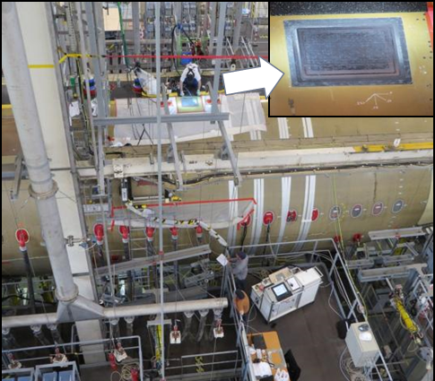
Various types of repairs were done in four different full scale test cells (refer to Figure 2), representing damages such as severe lightning strikes, aircraft operating events and accidental impacts produced during manufacturing or maintenance operations. Actually the following types of damages were considered:
- Fuselage skin damage without perforation
- Fuselage skin perforation with internal structure damage
- Fuselage skin damage in double curvature areas
- Fuselage skin damage in the passenger door surrounding area
- Wing skin damage
The repairs were inspected by ultrasonic inspection. Some were submitted to structural tests and some were sectioned for microscopic inspection to analise their quality in terms of the dimensional aspects of the joint (step depth, step length, overlap length, bond line thickness) and of the repair patch and adhesive film porosity. During the implementation of the repairs careful process follow-up and monitoring were performed.
| |
|
|
|
|
3 Results
The application of out of autoclave structural bonded repairs presents remarkable challenges and distinct characteristics:
- Materials are cured out of the autoclave with only vacuum pressure and local application of heat.
- Materials are cured at low temperature (typically 120ºC-140ºC) and are therefore very reactive and beyond certain thickness and size limits they may produce an uncontrolled exothermic reaction.
- Materials are exposed “on wing” repairs to temperature and humidity higher than those used in the clean areas of manufacture plants which impact their work life.
- The exposure to in-service conditions produces a pre-bond moisture condition in the parts different to the one in the manufacture plants. Eventually, the parent structure might be fully saturated with moisture. Repair qualification will have to determine the maximum acceptable pre-bond moisture and to define a feasible drying process prior to bond.
- In addition to that, the ply removal operation and the surface preparation prior to bond are essential to produce airworthy repairs. In the repair scenario the surface preparation is normally different from the ones in the bonded configurations used in the part manufacture. For composite repairs, after damage removal, the repair area is activated for bonding by light sanding and solvent or water cleaning. Bond line tests have to consider the surface preparation method. Surfaces activated by sanding have an expiration time that should be determined.
- The chemical and mechanical compatibility of the repair materials with each other and with the parent materials in the original components has to be demonstrated.
All these topics were the object of dedicated test campaings and feasibility trials. Main results are presented below.
3.1. Cure cycle development and proof
In order to avoid an out of control exotermic reaction during the cure of the repair patch a two step cure cycle was designed. The temperature and the time of the first dwell were adjusted so that the exothermic peak remains under control. For that, flat panels of increasing size and thickness containing the repair adhesive film and the repair prepreg were cured in a set-up simulating a repair condition where heat can not be dissipated easily and the temperature in the center of the repair pacth was monitored by means of thermocouples. The effect of the temperature tolerances was also determined as a function of the repair size and repair thickness.
At the same time, repair trials were performed in actual conditions in assembled parts and detailed thermal profiles during curing were carried out to detect if the cure temperature can be reached and maintained inside the specified tolerance. These trials showed that it was not possible to fulfil the standard temperature tolerance (+/- 5ºC) in some relevant component zones, but only an extended tolerance. Suitable insulation schemes were designed and tested. The feed-back from this experimental investigation was taken to the test plan, so that the relevant material properties were determined in test coupons cured with the minimum and maximum cure temperatures and the extended tolerances were validated. The effect on these extended tolerances in the exothermic reaction was also checked.
This approach is more realistic than requesting a tight tolerance that cannot be reached easily and can trigger the realization for most repairs of too many thermal profiles in the component damaging it eventually.
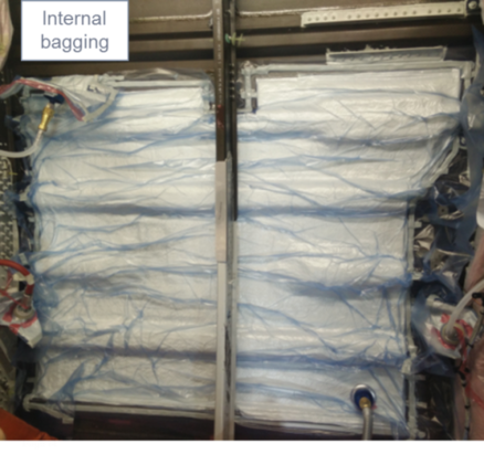
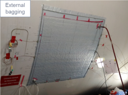
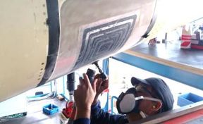
Guidance for the proper installation of insulation schemes, which depend on the specific location of the repair were included in the in-house and in-service repair documentation to facilitate the management of heat application in the repair area. In Figure 3 the vacuum bags installed in the inner and outer sides of the fuselage skin for the curing of a repair patch are shown. A mandatory thermal profile is also part of the repair instructions. The number of thermal profiles is limited in terms of maximum time and maximum temperature so that the original component is not damaged.
3.2. Vacuum application
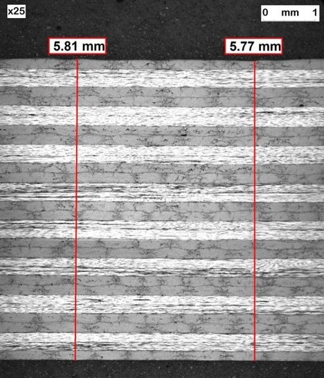
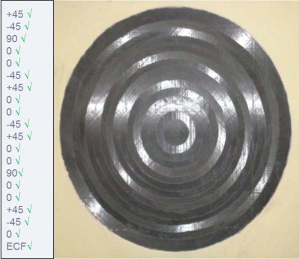
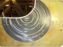
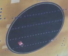
The repair materials are cured only under vacuum and their quality is highly dependent on the type of auxiliary materials used in the bag, the bag configuration, the debulking parameters and the vacuum application. These were studied as a function of the repair size and repair thickness to optimize the process and to define the feasible repair limits. Non-destructive and microscopic inspections were performed to check the bond line and repair patch quality. If the vacuum parameters are well controlled, thick repair laminates of very high quality can be produced (see Figure 4).
It was also found that it is necessary to check the air tightness of the original structure before the repair materials are applied (e.g. when fasteners were removed in the repair area and the holes were filled with paste adhesives or similar, in perforating repairs with backing plates, in repairs with few original plies remaining). A vacuum bag with the same size, vacuum bag materials and configuration (except the heating blanket and the insulation plies related with the thermal profile and heat distribution and uniformity) has to be installed on the same location as the final vacuum bag for curing the repair patch. The vacuum leak check is performed and if not successful, actions must be taken in the original structure to provide air tightness, such as the installation of a backing plate and vacuum bag in the back side of the repair area or additional rework of areas filled with adhesive paste, if applicable. Once these corrective actions have been taken, the vacuum leak check must be repeated to ensure that the airtightness has been achieved.
As indicated before for the heat application, the in-house and in-service repair documentation contains detailed instructions for the debulking steps and the vacuum cure.
3.3. Material handling
It is well known that thermoset resins are storage time, out time and temperature sensitive as well as affected by moisture and humidity. Therefore these materials need special handling and storage in order their processability is not affected and the end product properties are guaranteed. Contamination has to be also avoided by all means, because it will invariably reduce the properties, in most cases to unacceptable levels.
The limits and requirements applicable to all steps of material storage and handling since material manufacture at the material supplier until cure shall be defined. These are determined by testing the relevant chemical, physical and mechanical properties and are listed in the material and process specifications.
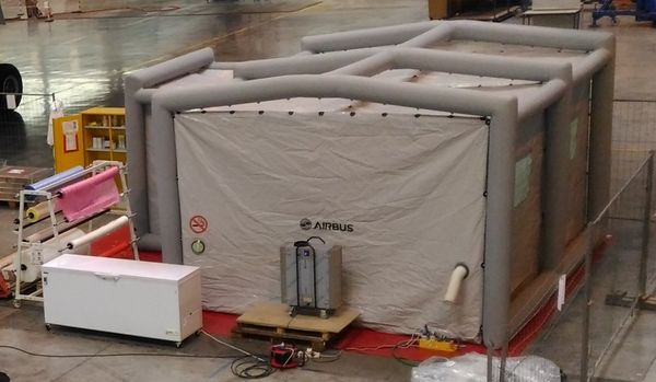
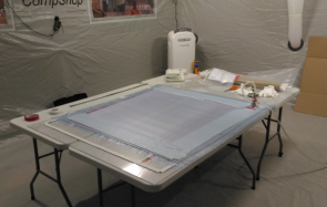
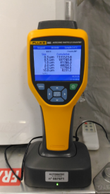
What it is very specific of repair materials is the last step in the material handling, since the commencement of the repair until repair cure, because the clean area conditions of the manufacture plants are not available at many in-service repair shops. On one hand, dedicated test campaigns were launched to evaluate the effect of exposure to temperature (up to 30ºC) and humidity (up to 75%RH) on the material properties. On the other hand, repair instructions were completed with detailed instructions for the material preparation steps, material application and handling until cure. The material preparation steps are still required to be accomplished in clean area conditions, which can be made available by using portable devices as the one shown in Figure 5.
Environmental conditions for the application of materials in the repair area in the aircraft were restricted to a maximum of 30ºC and 75% RH. If these cannot be reached a portable diving bell attached to the aircraft has to be used. Strict requirements regarding cleanliness and exposure to UV were also defined.
|
|
3.4. Pre-bond moisture and drying prior to bond
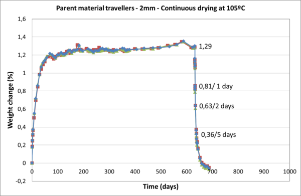
The mechanical performance of bonded composite repairs depends on the moisture content of the adherents. Eventually, the parent structure to be repaired in service might be fully saturated with moisture and drying it takes long times as can be seen in Figure 6 for 2 mm thick parent material travellers. It took 5 days of continuing drying at 105ºC in an oven to reduce substantially the moisture content. Similar results were found for other epoxy composite materials of the same type.
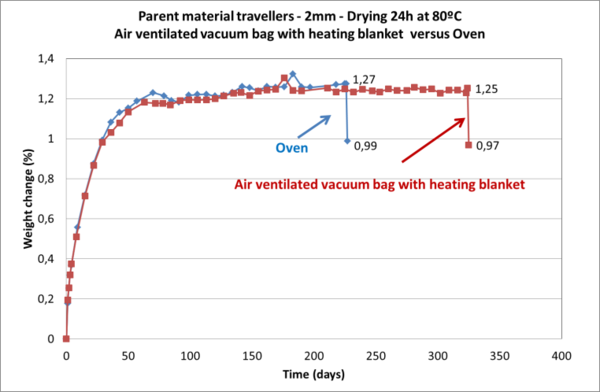
Alternative drying procedures were tried in order to see if shorter drying times could be achieved. Namely, air ventilated vacuum bags and standard vacuum bags, both with heating blankets, were tested and results compared with the ones obtained with the oven. No relevant difference was found among the different drying methods. Figure 7 shows the comparison of the air ventilated vacuum bag with heating blanket and the oven results.
Considering these results and the repercussions in the repair time and in the aircraft operational stoppage time a test campaign was launched to evaluate the effect of the pre-bond moisture content on the mechanical performance of the repair joint and on the failure mode. For the specific repair system under study a compromise between short drying times and mechanical performance could be found. Actually, it was possible to replace a dedicated drying process by the mandatory thermal profile in the repair area prior to bond, thus reducing significantly the overall repair time.
3.5. Ply removal
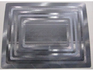
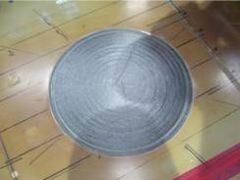
Ply removal in stepped and scarfed bonded repairs is an essential operation, which must produce a bonding surface matching the repair drawing and fulfilling tight dimensional tolerances for an effective load transfer. When performed manually, it is a time consuming and challenging process which requires very skilled technicians. With adequate training and practice results can be however remarkably good (see Figure 8 and Figure 9). The automation of the process presents clear advantages, but whatever the system used for automatic ply removal, it requires qualification prior to use. As an example, Figure 10 shows a typical microscopic inspection carried out during the qualification of automated abrasive water jet for ply removal.
The key product characteristics of the ply removal process were defined and included: the dimensional requirements listed in Table 1, the avoidance of any contamination introduced by the process, the absence of damages induced by the ply removal, the guaranty of the initial damage is fully removed and the bond line performance. Key product characteristics and requirements were associated with the key process parameters.
| Dimensional requirements |
| Shape and overall dimensions |
| Number of steps or scarf length and length tolerance |
| Step length and step length tolerance |
| Ply removal area with the right ply orientation and tolerance |
| Scarf angle and angle tolerance |
After ply removal, subsequent steps of the repair process (NDI if required, thermal profile, vacuum leak checks) are carried out followed by the activation of the surface for bonding.
3.6. Validation of the surface preparation prior to bond and material compatibility tests
The relevance of the surface preparation for bonding in the strength, durability and long term behaviour of the bonded joint is well known. It has to be carefully defined and checked by means of dedicated test campaigns. Surface preparation by sanding and cleaning is the state of the art for bonded repairs, but the precise description of the abrasives, tools, cleaning agents and operations (sanding direction, renewal of abrasives, etc.) must not be neglected. Only trained and certified technicians must carry out this critical step. The prepared surfaces have an expiration time that must be defined by testing. Cross contamination shall be avoided by all means by applying the proper cleaning and masking procedures. A wettability test will confirm if the surface is ready for bonding. These detailed instructions are part of the repair procedures for production and in-service.
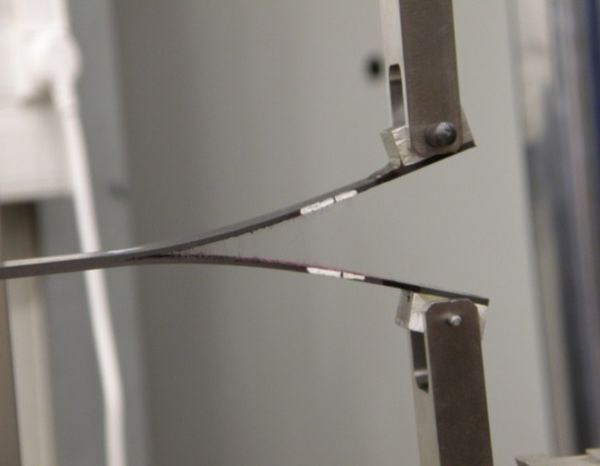
The chemical and mechanical compatibility of the repair materials with each other and with the parent materials in the original components was also carefully studied. Bond line tests were performed on bonded specimens prepared with the defined repair process (same surface preparation, same cure cycle, same vacuum bag). Pre-bond moisture may influence the results in terms of strength and failure mode. Therefore, the preparation of the parent semi-panels prior to bond was controlled carefully and the pre-bond moisture monitored precisely. The test matrix included the operating conditions and the environmental aging to discard incompatibility issues which may arise at temperatures other than room temperature or after ageing. The intended application drove the selection of the most appropriate configuration and test. Fracture toughness mode I test (see Figure 11) was a fundamental part of the testing as it is very sensitive to incompatibility issues.
The same types of tests are used to validate the surface preparation method and therefore these campaigns were made in combination to each other.
The influence of the human factor was considered by manufacturing co-bonded coupons for testing in three different shops. The effect of the storage time and work time in production and in-service conditions was also studied as well as the effect of low, medium and high pre-bond moisture.
The validation of the surface preparation method and the compatibility demonstration was the output of these test campaigns.
3.7. Qualification tests
The studies and tests campaigns indicated above were completed with the standard qualification tests typical of structural carbon epoxy prepregs and adhesive films to determine the lamina and the laminate properties of the repair prepreg and the bonded joint properties. A robust database was produced to be part of the design values generation and environmental knock down factors setting. The planned use of the repair materials and the certification requirements drove the selection and amount of qualification tests. The testing included the determination of the relevant properties for the installation of fasteners in the repair patch allowing the use of hybrid bonded- bolted repairs if necessary.
4 Conclusion
The coordinated approach used in this project combining at every step of the development material characterization tests and process trials in actual repair conditions proved to be very efficient for the achievement of a robust and reliable repair system and process for out of autoclave structural bonded repairs of highly loaded primary structures. The critical process steps were identified and adequate methods developed to guarantee the repair quality. The lessons learned in the experimental implementation of the repairs were taken back to the material test campaigns, so that they were performed using the actual process parameters. Thanks to this approach the lead time for delivery of results was optimized.
References
- 1. Read, Bill “Composite Repairs - Learning new rules”, Aerospace International, February 1, 2012
- 2. Introduction and overview [Chapter 1]
A.A. Baker, L.F. Rose, R. Jones (Eds.), Advances in the bonded composite repair of metallic aircraft structure, Elsevier, London, UK (2003)
- 3. Bonded Repair Size Limits, FAA, PS-AIR-100-14-130-001, 11/24/14
- 4. Bonded Repair Size Limits in accordance with CS-23, CS-25, CS-27, CS-29 and AMC 20-29. EASA CM No.: CM-S-005 Issue 01 issued 11 September 2015
Document information
Published on 14/04/19
Accepted on 14/04/19
Submitted on 14/04/19
Volume 03 - Comunicaciones Matcomp17 (2019), Issue Núm. 2 - Aplicaciones, uniones y reparaciones de los materiales compuestos, 2019
DOI: 10.23967/r.matcomp.2019.04.012
Licence: Other
Share this document
Keywords
claim authorship
Are you one of the authors of this document?
