Abstract
The investigation of modeling the time evolution of a folding wing during the morphing process and the dynamic characteristics analysis is carried out. The governing equations with uniform form are developed from the integration of floating frame method in multi-body dynamics and component mode synthesis in structural dynamics. The time-dependent aerodynamic force is taken into the governing equations. The equation achieves the time-dependent coupling between structure and aerodynamics and avoids the data transmission and low efficiency, which holds true for the multi-segmented folding wing. The relative parameters in constraint equations are easily modified to be applied to both slow and fast-varying processes for a folding wing. Also, the influence of the velocity and attack angle on transient responses can be investigated. Transient response analysis shows that slower morphing means more stable transient responses. The flexibility of the folding wing has the significant influence on transient responses. To some extent, the aerodynamic force can be beneficial to the morphing process.
Keywords: Folding wing, multi-body dynamics, structural dynamics, aerodynamics, time-dependent coupling
1. Introduction
Some parameters such as position, mass center and inertia for different segment will be time-varying while the folding morphing concept is to change an aircraft’s wing configuration, resulting in significant changes of the dynamics for the design of the folding wing. Meanwhile, the investigation on dynamic characteristic plays an important role in the design and dynamic response improvement of a folding wing as well as the design of a control system.
Obradovic et al. [1-2] presented a simulation methodology from the integration of rigid-body dynamics and unsteady vortex-lattice method due to complex configuration for a gull-wing configuration, resulting in a six degree of freedom nonlinear equation of motion in which the changes in both the aerodynamic and inertial properties were taken into account. They analyzed the dynamics through nonlinear simulations. Selitrennik et al. [3] proposed an aeroelastic simulation of rapid morphing air vehicles, in which the time-varying coordinate transformation matrix was used to perform the fictitious-mass modal synthesis and the aerodynamic force was based on CFD. Ameri et al. [4] developed a multi-body modeling tool, in which aerodynamic loads based on quasi-steady linear vortex-lattice method was implemented. They investigated the dynamic and shape changing response of morphing aircraft and analyzed the effect of the variation in the shape on the inertia properties, the center of gravity location and modal parameters. Seigler et al. [5] carried out the dynamic analysis for a large-scale morphing aircraft based on the integration of the multi-body dynamic, aerodynamic theory and flight control theory. They focused on the effect of the time-varying aerodynamic force, inertial force and moment on the transient response. Zhao et al. [6] established a set of differential-algebraic equations that governed the time evolution of the folding wing during the morphing process by the integration of the floating frame method and modal component synthesis. They obtained the transient responses of the folding wing without aerodynamic force during a morphing process. Wickenheiser et al. [7] demonstrated the transient and steady-state behavior of a perching aircraft undergoing changes in flight condition and vehicle reconfiguration through analytical and empirical aerodynamic analysis, trim and stability analyses and flight simulation. Reich et al. [8] and Scarlett et al. [9] proposed an integated simulation approach of a unmanned combat aerial vehicle through the integation of finite element modelling, aerodynamic loading and continuous-time multi-body simulation. They mainly used the commerical software platform that was not convenient to integrate the time-varying aerodynamic forces into the structural dynamic system for a folding wing. Yue et al. [10] deduced the six degree of freedom nonlinear equation for a tailless folding wing morphing aircraft in wing folding process. They investigated the key factors which affected the dynamic charateristics of morphing process by quantity.
What have been obvious in the current dynamic research for a morphing wing is that there are two kinds of methods. One is that the six degree of freedom equations are obtained by some modifications in traditional dynamic modeling such as the inclusion of the variations in inertial properties, the center of gravity location and modal parameters, then achieving the dynamic response. However, this method is not accurate and comprehensive for the morphing process. Moreover, time-varying terms will result in the complex governing equations, implying the difficulties in finding the solution. The other is the establishment of the multi-body dynamic model from the integration the finite element method, multi-body dynamic theory and coupling the varied aerodynamic force. Nevertheless the time-varying aerodynamic is achieved by the interpolation of steady-state aerodynamic force at different configurations, implying that the effect of aerodynamic force on the transient response cannot be taken into consideration. Meanwhile, the structure dynamic, the aerodynamic force and the coupling between the structure and aerodynamic all is time-varying, indicating that it is not beneficial to the data transferring between commercial softwares and adds to the difficulty in modeling and analysis.
This paper describes the development of the transient dynamics modeling for a folding wing and the analysis of displacement and mechanic response is carried out. Firstly, the dynamic formulation for each component is established by integration of the floating frame approach in multi-body dynamics and component mode synthesis in structural dynamics. Then, the configuration for folding wing is expressed as the generalized coordinates in floating frame approach. According to current configuration, the unsteady aerodynamic force is achieved on the base of rational function approximation to Doublet Lattice Method, in which the angle of attack is taken into consideration. The equivalent structural force on the node is obtained by the virtual principle. Finally, the equations that govern the time evolution of the folding wing during the morphing process are established in MATLAB. The constraint equations are used to present the motion relation between each component. Investigations of time histories are presented for changing morphing velocity, free flow velocity and angle of attack.
2. Multi-body dynamic equations for folding wing
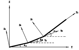
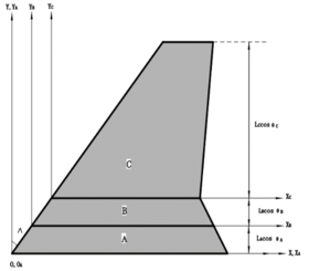
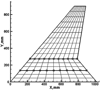
As shown in Figure 1, the folding wing consists of three separate components: the fuselage, the inboard wing and the outboard wing, denoted A, B, C, respectively. is the inertial frame, which is used to describe the motion of the system. , , are the floating frame to describe the elastic deform. , , are the folding angles of component A, B, C, respectively, which are positive in counter clockwise direction. All components are modeled by plates with the Young’s modulus of , Poisson’s coefficient of 0.33 and a density of , which are discretized using CQUAD4 elements with thickness in MSC.NASTRAN. Each node of this element has six degrees of freedom: three translations, namely, and three rotations, i.e., . For each component, all nodes at the interface are used to coordinate the boundary displacement. In this paper, the interfaces are assumed to be rigid. The finite element model for a folding wing is shown in Figure 2 .
|
|
| (a) | (b) |
| Figure 1. Schematic of folding wing and coordinate systems. (a) Top view. (b) Rear view | |
|
| Figure 2. Finite element model of folding wing |
By integration of the component modal synthesis and the floating frame approach, the equations of motion of the flexible component can be written as:
|
|
(1) |
where , , () are the generalized mass matrix, generalized damping matrix and generalized stiffness matrix, respectively, is the vector of constraint force, refers to the vector related to the gravity, represents the quadratic velocity vector that arises from the differentiating the kinetic energy with respect to time and with respect to the generalized coordinates, denotes the generalized aerodynamic force and is the generalized displacement of each component and it is written in detail.
|
|
(2) |
where is the position vector of the origin of each floating frame, is the modal displacement, and , which are the sub matrices in generalized damping matrix and generalized stiffness matrix, will be different when taken the aerodynamic force into consideration. The displacement of each component consists of large rigid body motions and small elastic deformations. Therefore, the mass matrices are function of the generalized displacement.
3. Unsteady aerodynamic forces
An et al. [11] compared the quasi-steady and unsteady aerodynamic charateristics of variable swept wing aircraft in wing sweep angular velocity by 8 deg/s, 10 deg/s, 15 deg/s, 20 deg/s, and the aircraft dynamic response results were quite similar. Therefore, the dynamic response affected by unsteady aerodynamic force during morphing process can be ignored within a certain range of morphing velocity. Although Doublet Lattice Method is an aerodynamic finite element method for modeling oscillating lifting surfaces in subsonic flows, the unsteady aerodynamic force resulting from the small oscillation of lifting surface is mainly taken into consideration while the morphing velocity is rather small and the change of aerodynamic force is not significant. As the preliminary research of the aerodynamic force, the Doublet Lattice Method is adopted here. The equivalent structural force on each node can be achieved on the base of virtual principle. While taking account of the effect of angle of attack, the equivalent force can be written:
|
|
(3) |
where is the generalized aerodynamic influence coefficient matrix, , is a matrix used to extract the normal displace from structural node and and are the spline matrices generated by the Infinite Plate Spline (IPS) method, is the angle of attack. Hence and are relative with and are time-dependent vectors. is the area matrix of aerodynamic panels.
4. Equations of motion of the folding wing during morphing process
Here the equivalent force on structural node cannot be directly used to the response analysis in time domain, because in Equation (3) is in frequency domain. In order to convert to time domain, there are many methods of rational function approximation [12-14], but the Minimum-State Approximation is used here for simplicity and effectiveness. The approximation form is as follows:
|
|
(4) |
Here, , , , and are unknown matrices in the minimum state approximation, which can be calculated from the least square fit. is the aerodynamic lag matrix.
Introducing aerodynamic state variable yields:
|
|
(5) |
where is the reference length, , , , , , are modal mass matrix, modal damping matrix and modal stiffness matrix, which are still the sub matrices in generalized damping matrix and generalized stiffness matrix. There exist two kinds of constraints for morphing motion, namely the kinematic constraints and the driving constrains. They can be expressed as
|
|
(6) |
where
|
refers to the desired folding angle. Components A and C are kept horizontal. Considering the constraint equation, can be replaced with , introducing the vector of Lagrange multipliers . is the constraint Jacobian equation. The resulting equation for morphing process can be as follows:
|
|
(7) |
where
|
|
Evidently, the equation above is a set of differential-algebraic equations. It can be solved by the method proposed by Baumgarte [15]. Differentiating Equation (6) with respect to time yields:
|
|
(8) |
Differentiating Equation (7) with respect to time again yields:
|
|
(9) |
Combining Equations (8) and (9),One can rewrite Equation (7):
|
|
(10) |
where . and are positive and play the rule of control terms which achieves the stability.
5. Transient response analyses for a folding wing
To predict the transient response for a folding wing, the folding angle can meet the following rule.
|
|
(11) |
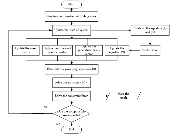
where stands for the steady state angle, is the time that the folding angle goes from to . The whole program is established in MATLAB, which can be solved by the computational algorithm in Figure 3. The first six modes of each component are used and the modal damping ratio is 0.02. Therefore, there are 46 equations in Equation (9). and can be set to 5 and 10, respectively. To determine the effect of aerodynamic force, the transient response of the rigid and flexible wing with gravity can be performed first, then the one with gravity and aerodynamic force.
|
| Figure 3. Computational algorithm for the dynamic analysis |
5.1. Transient response of rigid folding wing with gravity
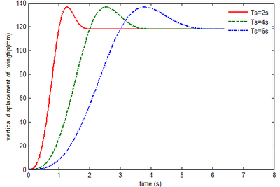
To determine the effect of aerodynamic force on the transient response, the response of rigid folding wing with gravity can be carried out firstly. Figure 4 shows the vertical displacement of the wingtip. The final displacement is 118.2mm for different . When is set to 2 , 4 , 6 , equals , implying that component B is perpendicular to components A and C and the displacement is the maximum. The greater , the slower the morphing process.
|
| Figure 4. Displacement response of the wingtip of rigid folding wing with gravity |
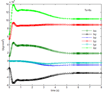
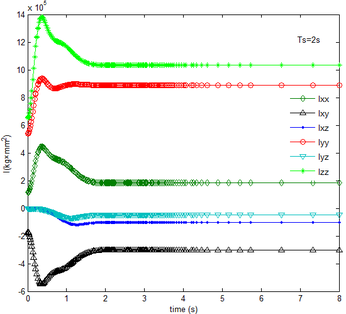
During the morphing process, the inertia tensors of each component vary relative to the inertial coordinate. Superimposing the tensor of each part, which is obtained in the inertial coordinate, the inertia tensor of the folding wing can be obtained. As shown in Figure 5, it can be seen that for different , the inertia tensor remains constant at the end of the folding motion as the time changes. And the rotational inertia Izz, Iyy, Ixx in the three directions sequentially decrease and remain positive, which is consistent with the definition of the moment of inertia, while the inertial product Ixy, Ixz, Iyz are negative. The more slowly the folding motion is, the slower each component of the inertia tensors varies.
|
|
| (a) | (b) |
| Figure 5. Time history of inertial tensor. (a) . (b) | |
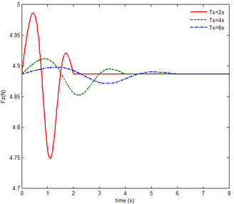
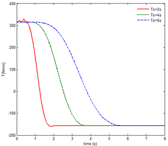
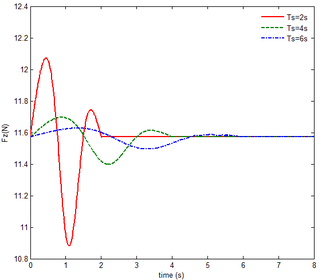
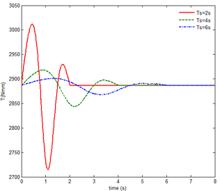
The mechanical responses of the rigid folding wing with gravity are shown in Figure 6.
In Figure 6, the resulting reaction force and resulting reaction moment acting on the rigid component A are not shown, since the resulting reaction force is the gravity of the component A, i.e. 6.542 , the resulting reaction moment resulting from gravity, namely 427.6 . The motion of the rigid component A in the floating frame is the same with that of the inertial coordinate. has no effect on the mechanical response of component A. So the resulting reaction force and resulting reaction moment acting on the rigid component A are not shown in Figure6. It can be seen, however, that the stable steady value of the resulting reaction force on the rigid component B is equal to the gravity of the component B at the beginning and the end of the folding motion, i.e., 4.89 . And the resulting reaction moment acting on the rigid substructure B is about 341.36 at the beginning and -157.18 in the end. The negative value represents the moment in the opposite direction. The initial and steady values are equal to the moments resulting from the gravity of the component B. At 1.27 , 2.5 , 3.81 , the folding angle equals , implying that the center of gravity passes through the floating frame, and the gravity produces a moment of zero. In Figure6, both the initial reaction force and the steady one acting on the rigid component C are the same, i.e. 11.564 . The initial and steady values of the reaction moment are the same, namely 2885 . The reason is that the component C is always kept in horizontality during the morphing process. Hence the center of gravity of the component C does not change much, relative to its floating frame. Either the resulting reaction force and moment acting on the rigid substructure B or the reaction force and the moment acting on the rigid substructure C vary with the increase of time. Moreover, the smaller , the more significant the variation. Due to the smaller , the deformation velocity and the quadratic velocity vector that arises from the differentiating the kinetic energy with respect to time and with respect to the generalized coordinates is greater, so the resulting force is greater. It is obvious that the slower morphing help to reduce the force acting on the rigid components B and C. Nevertheless the decrease of moment is not obvious, because points to the axis, producing no additional moment.
5.2 Transient response of rigid folding wing with gravity and aerodynamic
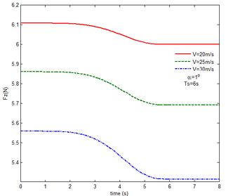
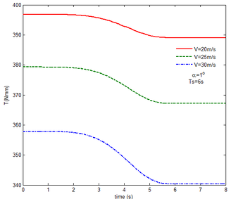
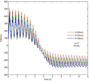
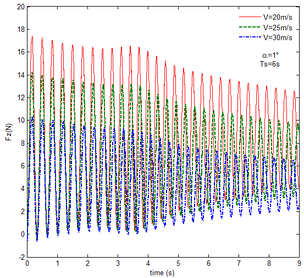
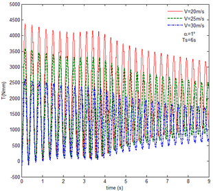
Then, the transient responses of the rigid folding wing with gravity and aerodynamic force is compared with ones in Section 5.1 to reveal the effect of aerodynamic force on the transient response. When the morphing process is relatively slow, the unsteady effect of the aerodynamic force can be ignored. Hence, here is set to , indicating that the process is relatively slow. Since the folding wing is rigid, the displacement response of the wingtip is consistent with one of the rigid folding wing with the gravity, implying that the vertical displacement response of the wingtip with gravity and aerodynamic force is shown in Figure 4, the corresponding displacement response corresponds to . Therefore, only the mechanical response is analyzed at different velocities and angles of attack, respectively, as shown in Figures 7 and 8. The free flow velocity is set to 20 , 25 and 30 , and the angle of attack equals to , and . Compared with the mechanical responses of the rigid folding wing with gravity, namely, the corresponding curves in Figure 6, it can be found that the aerodynamic force changes the mechanical response.
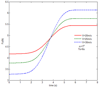
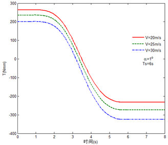
As shown in Figure 7, within the constant angle of attack and a certain free flow velocity range, as the velocity increases, the resulting reaction force and moment on the components A and C as well as the reaction forces and moments acting on the component C are reduced with gravity and aerodynamic force when the folding motion stabilizes. For the component B, the resulting reaction force and moment decrease as the velocity increases with the folding angle less than . On the contrary, those increases with the folding angle more than . The reason for this phenomenon is as follows. The components A and C always keep horizontal during the morphing process, in which the direction of the aerodynamic force is opposite to the direction of gravity. Hence the direction of gravity is always opposite to the one of aerodynamic force. And as the velocity increases, the aerodynamic force is also increasing, so the resulting force and moment acting on the components A and C are reduced. The direction of the aerodynamic force of the component B is normal along the wing surface in the folding process. There is a component of the aerodynamic force in the positive direction of the axis Z of the inertial coordinate with the folding angle less than , implying that it can weaken the influence of gravity. However, the aerodynamic force has a component in the negative direction of the Z axis of the inertial coordinate with the folding angle more than . Therefore, at the beginning, the resulting reaction force and moment of the component B are reduced with the increase of the velocity. At the end, the resultant force and moment increase. For the component A, the resulting reaction force and moment are not constant. This is due to the fact that the aerodynamic forces of the various components of the entire folding wing are interrelated, and the aerodynamic force on the component A will change as the configuration of the wing changes. Therefore, the resulting reaction force and moment on component A are slowly reduced and then remain stable. For the component C, it can be seen that the reaction force and moment increase first and then decrease from the partial magnification of (e) and (f). The reason is partly similar to the one for the mechanical response of a rigid folding wing with gravity. Another part of the reason is due to the folding wing in different configurations, the aerodynamic changes on component C.
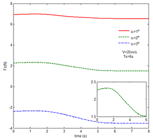
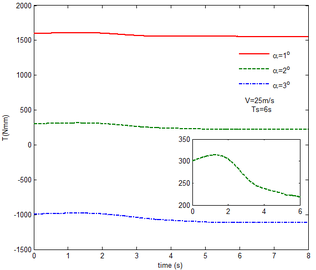
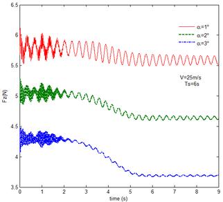
The mechanical response of the rigid folding wing with different angle of attack is shown in Figure 8 with the constant free flow velocity. The mechanical response is similar to ones in Figure 7. The angle of attack increases and the aerodynamic force effect increases. The resultant force and moment are reduced.
From Figure 8, it can be seen that with the increase of the angle of attack, the resulting reaction force and moment acting on the rigid component A and the reaction force and moment acting on the rigid component C are reduced at the constant free flow velocity. For the component B, with the increase of the angle of attack, the resulting reaction force and moment are reduced with the folding angle less than . Meanwhile, the resulting reaction force and moment is increased with the folding angle more than . The cause of this phenomenon is similar to the reason for the mechanical response of a rigid folding wing at different velocity. It is worth noting that for a rigid component C, the reaction force and moment become negative with the angle of attack . From the aerodynamic theory, within a certain angle of attack range, the lift increases with the increase of the angle of attack. The aerodynamic force acting on the component C is greater than its gravity, so the reaction force is downward, and the reaction moment is opposite to the X-axis direction of the inertial coordinate.
5.3 Transient response of flexible folding wing with gravity
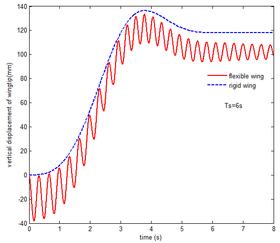
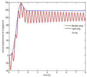
In order to analyze the effect of aerodynamic force on the transient response of a flexible folding wing, the aerodynamic effect is not taken into account, implying that, the aerodynamic relation is neglected in Equation (10). And transient response of the flexible folding wing is analyzed with gravity. The vertical displacement response of the wingtip is shown in Figure 9. When is set to 2s and 6s, respectively, the component B is perpendicular to the components A and C in the vicinity of 1.27s, 3.81s and the vertical displacement of wingtip reaches the maximum. Obviously, the flexibility has a great effect on the displacement response of the wingtip. During the morphing process, the displacement of the wingtip is prone to convergence, and stability value is smaller than that of the rigid wing in the end. Due to the structural damping in Equation (10), the displacement response tends to converge. The larger , the less the oscillation of normal displacement of the wingtip. The oscillation of the displacement of the flexible wing is obvious with gravity.
|
|
| (a) | (b) |
| Figure 9. Displacement response of the wingtip of flexible wing with gravity. (a) . (b) | |
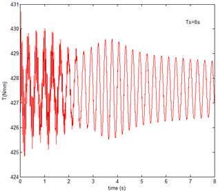
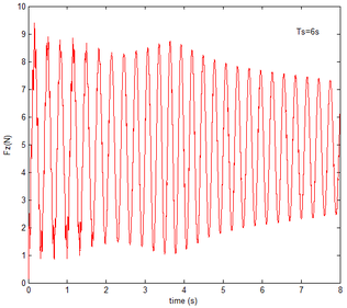
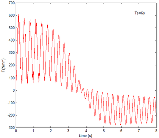
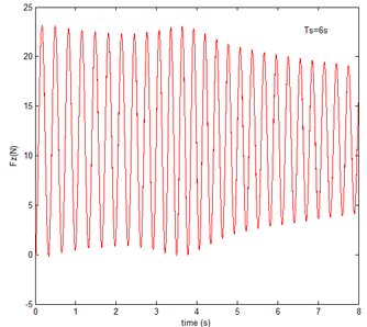
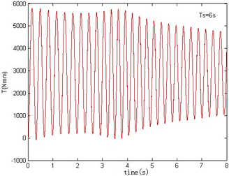
As shown in Figure 10 the flexibility of the wing has a great influence on the resulting reaction force and moment acting on the components A and B, and the reaction force and moment acting on the component C with gravity. Moreover, varies from to , the mechanical response shows a trend that is first oscillation convergence and then divergence. After is greater than the mechanical response is convergent.
For the rigid component A, the resulting reaction force and moment are constant, while the resulting reaction force and moment has a substantial oscillation, treated as the flexible one. Moreover, the resulting reaction force and moment vibrate near 6.542 , 427.75 , which are the force and moment arising from the gravity of the component A, indicating that the deformation of the flexible substructure A is small and its center of gravity position does not change significantly.
Compared with (c) and (d) in Figure 6, the resulting reaction force acting on the flexible component B has a large oscillation, which has changed the trend in the rigid state, but shown a convergence trend as time increases. For the resulting reaction moment, the trend is basically similar to the one in the rigid state, just with a little oscillation. Compared with (e) and (f) in Figure 6, the reaction force and moment acting on the flexible component C are tend to converge. Therefore, the flexibility of the wing folding has a significant effect on the response.
5.4 Transient response of flexible folding wing with gravity and aerodynamic force
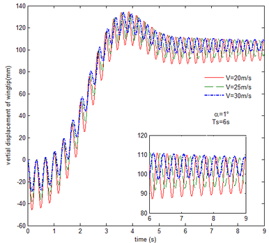
Finally, the transient response of the flexible folding wing with gravity and aerodynamic force is obtained and analyzed at different free flow velocity and angle of attack, respectively, as shown in Figures 11 to 14. Compared with the results in Figures 9 and 10, the effect of aerodynamic force on the transient response of flexible folding wing is revealed. Here the selection of velocity and angle of attack is consistent with section 5.2. When the angle of attack is constant, the displacement response of the wingtip at different free flow velocity is shown in Figure11. Apparently the displacement response has a large oscillation due to the flexibility of the wing. But the oscillation at the end of morphing process decreases as the velocity increases in the partial enlarged view. This is mainly due to the existence of aerodynamic damping. With the increase in the free flow velocity, the aerodynamic damping is enhanced. Hence, the aerodynamic force is beneficial to the morphing process.
|
| Figure 11. Displacement response of the wingtip at different velocities |
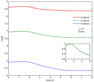
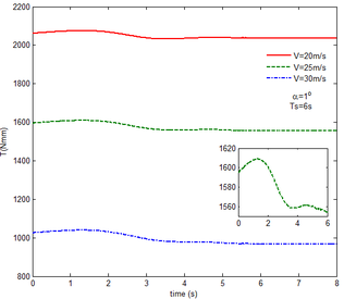
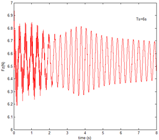
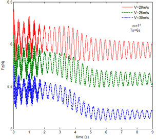
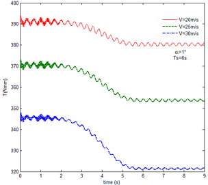
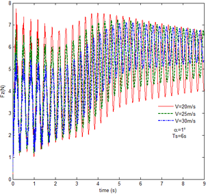
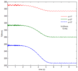
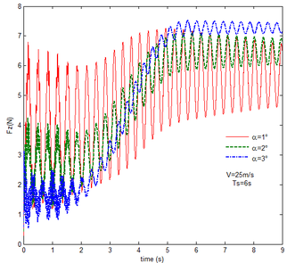
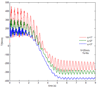
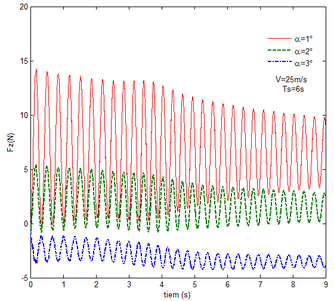
From Figure 12 , the resulting reaction force and moment acting on the flexible components A and B, the reaction force and the moment acting on the flexible component C are convergent with gravity and aerodynamic force. With the increase of velocity, the aerodynamic damping effect is enhanced and the oscillation is reduced. Compared with Figure 7, for the flexible component A, at the end of the morphing process, the resulting reaction force and moment are smaller under the same conditions. For example, with the free flow velocity 30 m/s, the resulting reaction force is 5.314 , the resulting reaction moment is 340.4 for the rigid condition, while the resulting reaction force and moment are 5.221 and 321.7 for the flexible condition, respectively. For the flexible component B, only the resulting reaction force substantially centers on the results under the rigid condition throughout the morphing process and oscillates. The resulting reaction moment centers on the results under the rigid condition with the folding angle less than , while the resulting reaction moment is less than the one for the rigid wing with the folding angle more than . For the flexible component C, the reaction force centers on the result of the rigid condition during the morphing process.
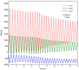
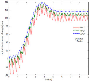
With gravity and aerodynamic force, the vertical displacement response of the wingtip at different angles of attack is shown in Figure 13. As the angle of attack increases, the oscillation of the wing tip is significantly reduced. When the angle of attack is set to , the initial value of the displacement is positive, indicating that the aerodynamic force acting on the folding wing is greater than its gravity and the deformation is positive. When the angle of attack is and , the aerodynamic force acting on the folding wing is smaller than its gravity, the deformation is negative. So the initial value of the wingtip is negative. With the increase of the angle of attack, the aerodynamic force acting on the wing is also increasing, the resultant force is reduced.
|
| Figure 13. Displacement response of the wingtip at different angles of attack |
Similar to the mechanical response of the flexible folding wing at different free flow velocity, with aerodynamic force, the resulting reaction force and moment acting on the flexible components A and B, the reaction force and moment acting on the flexible component C has the trend to convergence at different angles of attack in Figure 14. And with the increase of the angle of attack, the oscillation of the mechanical response is reduced due to the decrease in the elastic deformation. Compared with Figure 8, under the same conditions, at the end of morphing process, the resulting reaction force and moment on the flexible component A are smaller than those under the rigid condition. Taken the flexible component A as an example, with the angle of attack the resulting reaction force and moment are 3.676 and 206.4 while the resulting reaction force and moment are 3.977 and 245.5 under the rigid condition. For the flexible component C, the reaction force substantially centers on the one of the rigid wing and oscillates up and down. The reaction moment has a little different. With the angle of attack , it centers on the results in the rigid condition. However, it is less than the results of the rigid wing with the angle of attack . In the case of the rigid wing, the moment is -1117 , while the one is -843.2 for the flexible wing. So to a certain extent, the aerodynamic force is beneficial to the morphing motion.
6. Conclusions
In order to analyze the dynamic characteristics of the wing during the morphing process, the dynamic governing equation of the folding wing in the morphing process is established and the response is analyzed in detail. The equation is established on the base of the floating frame method in multi-body dynamics and the component modal synthesis method in the structural dynamics, in which time coupling of the structure and the aerodynamics is achieved, and the relevant parameters in the constraint equation can be changed to analyze the transient response of the rigid and flexible folding wing in the slow and fast-varying process. Introducing the aerodynamic force in time domain, the effect of the free flow velocity and angle of attack on the response is investigated. The conclusions can be drawn as follows:
- The governing equation of the folding wing is established by the integration of the floating frame method and the component modal synthesis method to realize the time-varying coupling between the structure and the aerodynamics, which avoids the data transfer between the commercial software, the computational complexity and the computational efficiency. The proposed approach is applicable to multi-segmented wing, which is similar to folding wings.
- In the case of rigid folding wing, the slower the morphing process, the more stable the transient response. For the flexible folding wing, the slower the morphing process, the smaller the oscillation of the transient response.
- For the rigid wing, the resulting reaction force and moment acting on the components, as well as the reaction force and moment, are reduced with gravity and aerodynamic forces. So to a certain extent, the aerodynamic force can assist the morphing of the wing.
- With gravity and aerodynamic force acting on the flexible wing, with the constant angle of attack, the free flow velocity is larger within a certain range, the smaller the oscillation of displacement response of the wingtip. With the constant free flow velocity, the greater the angle of attack, the smaller the deformation of the wing in the morphing process within a certain range. Moreover, the oscillations of the resultant force and the moment are reduced.
Author Contributions
Y.N. (Yingge Ni) and W.Z. (Wei Zhang) conceived the whole numerical simulations; Y.N. (Yingge Ni) wrote the paper. Y. L. (Yi Lv) reviewed and edited the paper.
Conflicts of Interest: None.
References
[1] Obradovic B., Subbarao K. Modeling of flight dynamics of morphing-wing aircraft. J. Aircr., 48(2):391-402, 2011.
[2] Obradovic B., Subbarao K. Modeling of dynamic loading of morphing-wing aircraft. J. Aircr., 48(2):424-435, 2011.
[3] Selitrennik E., Karpel M., Levy Y. Computational aeroelastic simulation of rapidly morphing air vehicles. J. Aircr., 49(6):1675-1686, 2012.
[4] Ameri N., Lowenberg M.H., Friswell M.I. Modelling the dynamic response of a morphing wing with active winglets. AIAA Atmospheric Flight Mechanics Conference and Exhibit, Hilton Head, South Carolina, AIAA 2007-6500, 20-23 August 2007, .
[5] Seigler T.M., Neal D.A., Bae Jae-Sung, Inman D.J. Modeling and flight control of large-scale morphing aircraft. J. Aircr., 44(4):1077-1087, 2007.
[6] Zhao Y.H., Hu H.Y. Prediction of transient responses of a folding wing during the morphing process. Aerosp Sci. Technol., 24:89-94, 2013.
[7] Wickenheiser A.M. Garcia E. Longitudinal dynamics of a perching aircraft. J. Aircr., 43(5):1386-1392, 2006.
[8] Reich G.W., Bowman J.C., Sanders B.. Development of an integrated aeroelastic multibody morphing simulation tool. 47th AIAA/ASME/ASCE/AHS/ASC Structures, Structural Dynamics and Materials Conference, Newport, Rhole Island, AIAA 2006-1892, 1-4 May 2006.
[9] Scarlett J.N., Canfield R.A. Multibody dynamic aeroelastic simulation of a folding wing aircraft. 47th AIAA/ASME/ASCE/AHS/ASC Structures, Structural Dynamics and Materials Conference, Newport, Rhole Island, AIAA 2006-2135, 1-4 May 2006.
[10] Yue T., Wang L.X. Multibody dynamic modeling and simulation of a tailless folding Wwng morphing aircraft. AIAA Atmospheric Flight Mechanics Conference, Chicago, Illinois, AIAA 2009-6155, 10-13 August 2009.
[11] An J.G., Yan M., Zhou W.B., Sun X.H., Yan Z. Aircraft dynamic response to variable wing sweep geometry. J. Aircr., 25(3):216-221, 1988.
[12] Jones R.T. The unsteady lift of a wing of finite aspect ratio. NACA Report-681, 1941.
[13] Roger K.L. Airplane math modeling methods for active control design. AGARD-CP 228, pp. 1-11, 1977.
[14] Karpel M. Extensions to the minimum-state aeroelastic modeling method. AIAA J., 29(11):2007-2009, 1991.
[15] Baumgarte J. Stabilization of constraints and integrals of motion in dynamical system. Comput. Method Appl. Mech. Eng., 1(1):1-16, 1972.
Document information
Published on 12/01/21
Accepted on 10/10/20
Submitted on 27/05/20
Volume 37, Issue 1, 2021
DOI: 10.23967/j.rimni.2020.10.005
Licence: CC BY-NC-SA license
Share this document
Keywords
claim authorship
Are you one of the authors of this document?
