1 Introduction
The use of carbon fibre reinforced polymers in primary and secondary aircraft structures has significantly risen in the latest few decades, mainly due to their excellent fatigue endurance and high specific strength when compared to ordinary metallic materials. [[i]] Thermoset resin based carbon fibre reinforced polymers (CFRP) have been the most matured technology for airframe manufacturing due to its excellent mechanical properties. Nevertheless, there is a growing interest in the use of thermoplastic resin based CFRP in aviation industry as developments in new resins and manufacturing technologies close the gap in performance compared to thermoset.
Thermoplastic polymers can be heat-softened, melted and reshaped as many times as desired. Additionally, they can be stored at room temperature and have an unlimited shelf life. This leads to a waste save and allows for more flexible manufacturing processes. Furthermore, their re-formability enable the correction of production tolerance errors and most importantly, re-usability and recyclability features of this nature of resins provides a great opportunity to reduce drastically the environmental impact of the global fleet.
The work presented here is framed in DELTA, [[ii]] a European Research Project (Clean Sky 2 JU) lead by AERNNOVA which pursues the development and execution of innovative experimental test procedure that allow the validation of a thermoplastic composite fuselage panel, in order to apply these solutions in medium and long-range aircraft (LPA). One of the objectives of DELTA is to ensure the improved understanding of the structural response of a new concept for thermoplastic fuselage and proper design solutions for future application by means of experimental tests at two different structural complexity levels.
DELTA Project covers the topic JTI-CS2-2018-CFP08-LPA-02-23, which was launched by Clean Sky 2 Joint Undertaking at the 8th Call for Proposals. It belongs to the WP 2.1.4 of the LPA Programme Area, being part of the current Grant Agreement CS2-GAM-2020-LPA-AMD-945583-23.
For that, a mechanical characterization at coupon and detail level of the thermoplastic matrix carbon fibre reinforced polymer is developed. As a result of this research, the allowables have been obtained for the design of the curved thermoplastic fuselage panel. With this information, DELTA will conclude with of the experimental validation of a curved thermoplastic panel test representative of a long-range aircraft fuselage.
2 Materials and Methods
2.1 Material and manufacturing process description
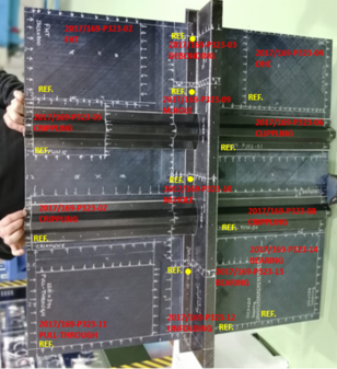
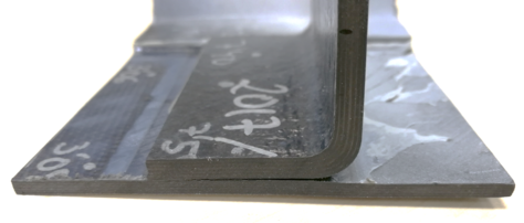
Figure 1 shows the final thermoplastic flat panel that was manufactured by FIDAMC, including the areas from where the specimens for Level 2 mechanical tests were extracted.
Whole component was developed by using a Carbon Fibre Reinforced Polymer, composed by a standard modulus carbon fibre and a semicrystalline thermoplastic matrix. The Ω-shaped stringers and the Z-shaped frame were manufactured by press-forming. The skin was obtained by automatic laying-up and in-situ consolidation.2.2 Mechanical tests
One of the objectives of this test campaign is to establish the fundamental material properties for subsequent use with structural analysis and design techniques. To this end, mechanical tests were carried out at the coupon and element levels for the characterization of the properties of the thermoplastic composite used in the fuselage panel manufacturing. In addition to standardized tests, tests were carried out to evaluate the behaviour of critical areas of the panel, such as the radius of the frames, the stringers, and the joint between the frame and the skin around the stringers (mouse-hole).
In the Table 1, the mechanical properties that were studied in this experimental test campaign are summarized. Number of specimens for each case is included. All of the tests were performed at RT conditions and no previous environmental conditioning was applied.| Test | Test Standard | Specimen dimensions (mm) | No. of specimens |
| FHT | ASTM D5766/ ASTM D6742 | 300 x 38.1 | 5 |
| OHC | ASTM D6484 Proc. B | 300 x 38.1 | 5 |
| Bearing | ASTM D5961 Proc. B | 342.9 x 38.1 | 3 |
| Crippling | Experimental procedures | 200 x 113 | 7 |
| Unfolding | 88 x 50 | 4 | |
| Debonding | 88 x 25 | 3 | |
| Mouse hole | 260 x 87 | 2 |
Once ELEMENT received the sections of the panel shown in the Figure 1, the specimens were extracted and prepared to perform the tests included in the Table 1. This preparation covered the installation of the stabilization tooling, installation of strain gages, drilling, etc. where applicable.
2.2.1 Filled-Hole Tension and Open-Hole Compression tests
The objective of these tests was to determine the properties of filled-hole tensile strength and open-hole compressive strength of the thermoplastic composite.
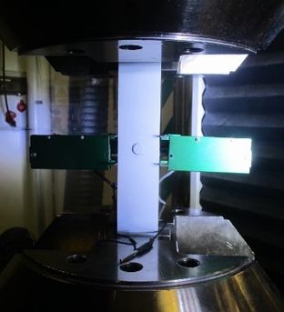
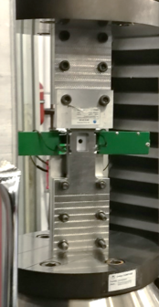
Filled-Hole Tension (FHT) tests were performed according to ASTM D5766/D5766M standard [[i]]. Provisions from ASTM D6742/D6742M [[ii]] were also followed. Open-Hole Compression (OHC) tests were performed according to ASTM D6484/D6484M standard, following procedure B [[iii]]. FHT and OHC tests were performed through a Universal Testing Machine Zwick Z250, equipped with a load cell up to 250 kN.
In the Figure 2, the set-up is shown for both tests. An edge-mounted average extensometer was used in these tests. In order to study specimens’ failure mode, the High-Speed Camera was used in FHT tests.
|
|
| a | b |
2.2.2 Bearing Strength tests
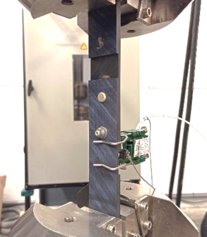
Bearing strength test aims to assess the bearing response of fastened joints using multi-directional polymer matrix composite laminates reinforced by high-modulus fibres by single-shear tensile loading of a two-piece specimen, according procedure B of the test standard ASTM D5961/D5961M [[i]].
|
These tests were conducted through a Universal Testing Machine Zwick Z100 equipped with a load cell up to 100 kN (Zwick Z100 BS1). The set-up for these tests is shown in the Figure 3. A face-mounted extensometer was used in the bearing tests.
2.2.3 Crippling tests
This test campaign covers the execution of quasi-static compression test on mono-stringers (skin + stringer), normally known as ‘crippling tests’. The crippling load is the ultimate load a stiffener loaded in uniaxial compression can undergo before final failure. This load can be experimentally determined if the stiffener is short enough, since long stiffeners often fail due to buckling before crippling load is reached.
An experimental procedure was developed for crippling test execution, including the design of the necessary tools to reproduce the representative boundary conditions. Seven specimens were extracted from the flat panel shown in the Figure 1 for execution of the crippling tests. Specimens’ length was 200 mm and specimen width was the total stringer width, 113 mm. In order to introduce compression load, aluminium end blocks were installed in the specimens. End blocks with different length were used, achieving specimen spans of 120 mm and 150 mm. Due to the specimen length, no lateral stabilization was required. The specimens were instrumented with strain gages.
Crippling tests were performed by means of a SCHENCK 2.5 MN Universal Testing Machine. The set-up for crippling test is shown in the Figure 4. First, a pre-test up to 15% of predicted failure load was executed. Then, the specimen was subjected to monotonic compression loading up to failure. The displacement rate was 0.5 mm/min. Data acquisition was performed using MGCPlus system, which allows high frequency data acquisition (100 Hz), real-time monitoring of the results (loads, displacements, strains), and synchronization of all the measurements.
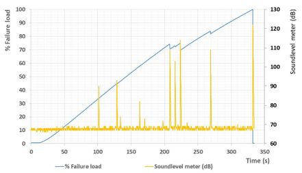
In addition to traditional strain gauges, digital image correlation (ARAMIS system) was included to obtain the strain field in the central area of some of the specimens (skin surface). To this end, the specimen was white-painted and this surface was then prepared to monitor strain level. Likewise, laser displacement sensor with 8 µm accuracy was used to obtain actual displacement of the specimen, and avoid the error coming from the adjustments of the test machine in displacement recording. Additionally, High-Speed Camera was used to study failure mode of these specimens. Crack events were also recorded by means of a sound-level meter.
2.2.4 Unfolding and debonding tests
Test procedures were developed with the purpose of obtaining information on the unfolding and debonding failure modes and their admissible values for the structural detail formed by the frame-skin joint. The purpose was to obtain which were the primary and secondary failure modes depending on the loading introduced to the structure and to propose a design optimization for scaling-up to Level 3 specimen design.
Unfolding and debonding tests were performed by means of a Zwick Z100 Universal Test Machine, equipped with a load cell up to 100 kN. First, a pre-test was applied up to 15% of estimated failure load. After unloading, monotonic loading up to failure was applied. The displacement rate was 0.5 mm/min. All of the specimens were instrumented with strain gages. In order to assess intermediate cracks, sound-level meter was used in these tests.
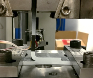
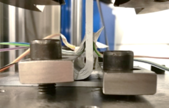
Unfolding test set-up was modified according to the results obtained in the tests. The test set-up for unfolding specimens #1 and #2 is shown in the Figure 5. In first group of tests, a plate was used to clamp the skin-frame joint. The distance between frame radius and the clamping plate was reduced from specimen #1 to specimen #2.

|
|
| a | b |
The test set-up for the specimen #3 is shown in the Figure 6. In this test, fasteners were used to clamp the skin-frame joint.
Clamping by means of a plate was proved to be a better solution to obtain unfolding as primary failure mode. Thus, specimen #4 was tested according to this configuration. In this case, distance between frame radius end and clamping plate was 12 mm.
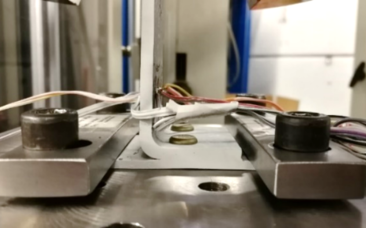
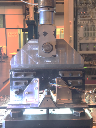
In debonding tests, the set-up was similar for all the specimens. An example is shown in the Figure 7.2.2.5 Mouse hole tests
The purpose of these tests is the characterization of the joint between the frame and the skin around the stringers, i.e. mouse hole area, when it is subjected to tensile loads. As a result, the admissible values of debonding or frame/stringer delamination failure mode are obtained.
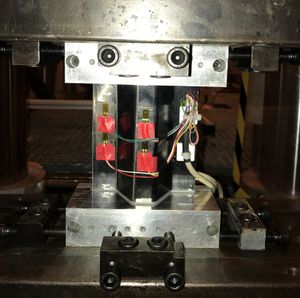
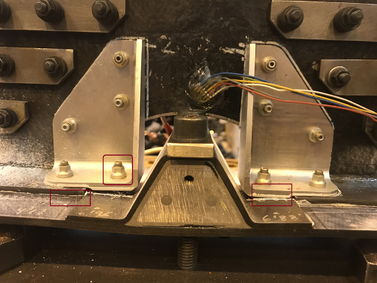
Mouse hole tests were performed using a hydraulic actuator in a custom test rig equipped with a load cell of 250 kN. The displacement rate was 0.5 mm/min. Two different specimen configurations were tested. The first specimen was tested according test configuration 1, which includes metallic fittings (named as “clips”) reinforcing the joint between frame, stiffener and skin. In the Figure 8, the set-up for this mouse hole test is shown. Once this configuration was tested and structure behaviour including failure mode was valid, the second mouse hole was tested according test configuration 2, which does not include the clips. This allowed to evaluate structure behaviour and feasibility of the design without this reinforcement. Specimens were instrumented with strain gages to check proper strain distribution. In order to detect intermediate cracks, sound-level meter was applied in these tests as well.3 Results
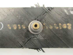
For all the FHT specimens, the failure occurred at the hole area. An example of this failure mode is shown in the Figure 9. The results of these tests have been compared to the ones obtained in the mechanical characterization of a thermoset pre-preg, M21/T800S, following the same Test Method. The filled-hole tensile strength is 30% lower than the resistance obtained for the thermoset composite.
|
|
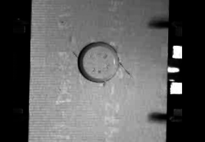
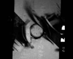
Images taken from the video-recording with High-Speed Camera of the fastener area during failure are shown in the Figure 10. The initiation and propagation of cracks around the fastener is observed.
|
|
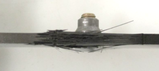
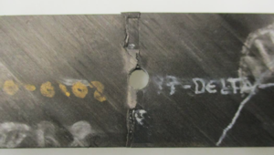
In all of the OHC specimens, failure also passed through the hole. An example of this failure mode is shown in the Figure 11. The open-hole compressive strength obtained for thermoplastic composite was higher (38%) than the resistance of the thermoset composite. Nevertheless, it should be noted that reference material, M21/T800S, was tested following procedure A of ASTM D6484/D6484M Test Method.
|
|
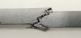
In bearing tests, for all of the specimens two failure mode were observed: laminate bearing at both holes as well as laminate pull-through at both holes in the laminate head side. An example is shown in the Figure 12. Additionally, one of the specimens exhibited fastener bending at the fastener head closer to the extensometer. The ultimate bearing strength as well as the offset bearing strength of the tested material were higher (69% and 58%, respectively) than the ones of the thermoset material taken as reference (M21/T800S). Nevertheless, different test procedures of the same Test Method were used: procedure B for thermoplastic composite and procedure A for thermoset composite.
3.1 Crippling tests
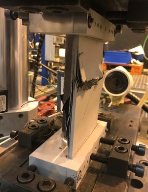
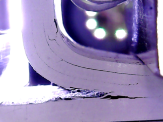
The Figure 13 shows an example of the crippling specimens after failure and its corresponding image taken from the High-Speed camera recording (Figure 14). Explosive failure mode is observed for all of the specimens.
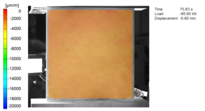
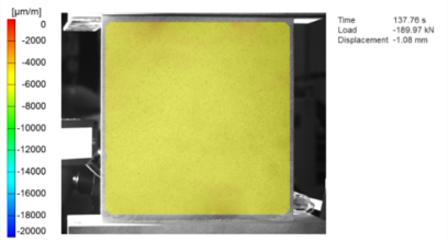
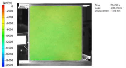
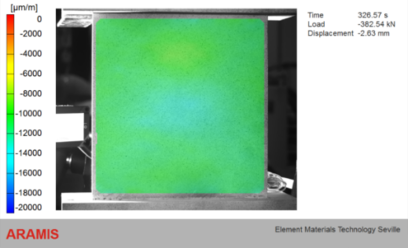
Figure 15 shows the evolution of the strain level in the specimen CR-4, measured through Digital Image Correlation, at (a) 0% load; (b) 25% load; (c) 50% load; (d) 75% load; (e) 100% load. It is observed a uniform deformation of the skin side of the specimen.

|
| a |
|
| b |
|
| c |
|
| d |
|
| e |
An example of load curve (expressed as percentage of failure load) correlated with the signal from sound-level meter is shown in the Figure 16. It can be observed that sound peaks match with small load drops before failure, which correspond to intermediate cracks in the specimen throughout the test.
Higher failure loads are observed for specimens CR-6 and CR-7. This is due to the greater thickness of these specimens, which were extracted from a section of panel area with extra thickness. From the mechanical test results, it can be stated that influence of span is not significant for this test specimen geometry.3.2 Unfolding and debonding tests
As commented before, this test presents the particular challenge in design of different boundary conditions in such way that the first failure of the specimens is provoked, on one hand, by a debonding between skin and stiffener and, on the other hand, by a delamination of the unfolded plies in the stiffener radius area.
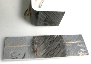
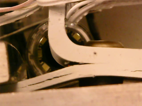
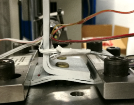
For unfolding specimens #1 and #2, debonding took place before failure of the radius occurred. Thus, a modification of the boundary conditions was necessary to obtain information on the desired unfolding failure mode.For this purpose, fastener clamping was proposed for the following test. This configuration resulted in a significant skin flexure took place during the test, leading to skin delamination before the final unfolding failure. The specimen after failure is shown in the Figure 18.
|
|
The failure mode of the fourth unfolding specimen was similar to the failure of specimens #1 and #2: debonding of the skin-frame joint took place before final unfolding failure.
Debonding specimen failure mode was the same for all the specimens.
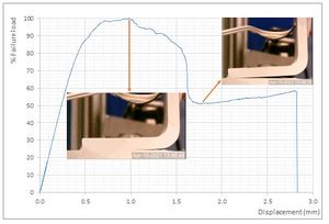
As it is shown in the Figure 19, the frame was debonded from the skin. Figure 20 shows an example of the progression of the debonding along with the load-displacement curve (load is expressed as percentage of failure load). The failure load in unfolding test configuration was 7 times higher than the failure load obtained in the debonding test configuration.As a result of this campaign, a set of failure loads was obtained for the different failure modes along with useful information for the structural joint design solution that is to be applied on the thermoplastic fuselage panel design.
3.3 Mouse hole tests
The Figure 21 shows the first mouse hole specimen after failure. As it can be observed, clip-stringer bolted joint failed. Debonding of skin-frame joint was also noticed.
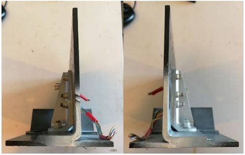
No damage was observed in the lateral edges of the specimen after failure (Figure 22).
Figure 23 shows the second mouse hole specimen after failure. As it can be observed, the specimen failed due to frame-skin joint debonding.
4 Conclusions
The mechanical behaviour of the thermoplastic material has been assessed, and the allowables have been obtained for the design of the curved thermoplastic fuselage panel.
Standardized test results showed a low level of dispersion, which reflects a suitable manufacturing process. Regarding element tests, it was found that debonding of skin-frame is a critical failure mode that should be controlled in the design of the sub-component tests. This behaviour is highlighted in mouse hole tests, where better results were obtained with the specimen reinforced by the clips. This solution will be finally adopted by the manufacturer, who will include the clips in the frames of the curved panel.
The advanced monitoring techniques, such as Digital Image Correlation, High-Speed Camera and sound-level meter, have been successfully applied. These techniques provided useful information about the deformation and failure mode of the specimens throughout the tests, which could not have been obtained with standard test instrumentation.
The execution of this test campaign has allowed to obtain valuable information about the mechanical behaviour of the fuselage panel components. This knowledge will be applied in the final design of the curved thermoplastic panel. Future validation of this aerostructure as part of DELTA will finally have a positive environmental impact. Due to its re-usability and recyclability advantages, usage of thermoplastic resin based carbon fibre polymers will mainly contribute to the reduction of Greenhouse Gas (GHG) emissions.
5 Acknowledgements
The research leading to these results has gratefully received funding from the European JTI- CleanSky2 program under the Grant Agreement nº 831862 (DELTA). This project is coordinated by Element Seville, and lead by AERNNOVA, as Topic Manager. Likewise, the authors wish to thank the collaboration with FIDAMC, as manufacturer of panel specimen.
References
[1] Oguzhan Bas, Elvan Ates, Fahrettin Ozturk. Thermoplastic Composite Materials for the Aerospace Industry. Res Dev Material Sci. 15(5). RDMS.000872. 2021. DOI: 10.31031/RDMS.2021.15.000872
[2] https://www.project-delta.es/
[3] ASTM Standard D5766/D5766M – 11, “Standard Test Method for Open-Hole Tensile Strength of Polymer Matrix Composite Laminates”, ASTM International, July 2018, DOI: 10.1520/D5766_D5766M-11R18.
[4] ASTM Standard D6742/D6742M – 17, “Standard Practice for Filled-Hole Tension and Compression Testing of Polymer Matrix Composite Laminates”, ASTM International, October 2017, DOI: 10.1520/D6742_D6742M-17
[5] ASTM Standard D6484/D6484M – 14, “Standard Test Method for Open-Hole Compressive Strength of Polymer Matrix Composite Laminates”, ASTM International, 2014
[6] ASTM Standard D5961/D5961M – 17, “Standard Test Method for Bearing Response of Polymer Matrix Composite Laminates”, ASTM International, September 2017, DOI: 10.1520/D5961_D5961M-17.
Document information
Published on 16/10/22
Accepted on 20/06/22
Submitted on 29/04/22
Volume 07 - COMUNICACIONES MATCOMP21 (2022), Issue Núm. 2 - Aplicaciones Industriales - Caracterización, 2022
DOI: 10.23967/r.matcomp.2022.10.004
Licence: Other
Share this document
Keywords
claim authorship
Are you one of the authors of this document?
