Abstract
Civil structures, once built and released for use, are expected to fulfil operational standards for extended periods. The fact, a civil structure´s life, is determined by temporary deterioration, harsh ambient, misuse, destruction, and, eventual rehabilitation for current use or conservation for historical reasons. Initially, vibrational analysis with stationary sensors, broad logistics and a large array of sensors to provide densely detailed data were required. The next evolutionary step; the simplification of the while-under-use data-acquisition stage; better, faster, more detailed parameters for diagnosis. With the structure under normal operation, a stationary reference sensor, a mobile sensor able to travel through specific trajectories over the structure, deep computational data analysis provides better, deeper, clearer frequencies, mode shapes and damping ratios. A structural health monitoring system should be able to reliably assess structural wellness under operational conditions. Such are the benefits of a mobile sensor monitoring and diagnosis system. This paper utilizes the time–scale analysis method and the Continuous Wavelet Transform (CWT) through a complex Morlet wavelet to extract modal parameters from the signal responses. The theoretical development is validated by numeric simulations on a simply supported beam and by double experimental confirmation on a pedestrian bridge at Universidad del Valle, in Cali (Colombia), by the technique herein, and by a stationary sensor scheme.
Keywords: Modal identification, mobile sensors, time-scale analysis, continuous wavelet transform
1. Introduction
Structural Health Monitoring (SHM) is an essential tool to determine the safety, usability and maintainability of critical structures such as bridges, buildings or dams for example. Structural modal parameters, that is natural frequencies, mode shape vectors, and damping ratios, are the most commonly used condition indexes for vibration based SHM and damage detection. Currently, a modal model of a structure can be derived by an Operational Modal Analysis (OMA) showing significant advantages over procedures requiring known excitation inputs; low cost, broadband excitation, and the continuous use of the structures in real-life operational conditions [1–4].
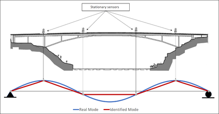
In a traditional modal identification method (Figure 1(a)), a commonly large number of stationary sensors are distributed in pre-defined locations along the structure. The modal coordinates are identified over such discrete points. To improve the spatial resolution additional gear, additional sensor setups as well as experienced staff for proper configuration would be required, a process which is further challenged by the physical constraints of a structure.
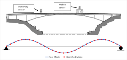
In mobile sensor setups (Figure 1(b)), sensors are mounted on mobile platforms to move along the structure as desired. A mobile sensing scheme offers clear improvements where a fixed sensor scheme falls short. With mobile sensing, few sensors, almost basic connectivity and lesser setup testing time can provide more spatial information than a dense fixed sensors network [5–8].
| |
| (a) | |
| |
| (b) | |
| Figure 1. Spatial resolution of mode shapes. (a) Stationary sensors. (b) Mobile sensors | |
Structural dynamic properties identification through Mobile Sensing has been a most concerned issue for the last decade. Recent studies have shown that mobile sensing schemes can record as much spatially dense information as stationary sensor schemes.
Zhu et al. [9], with the introduction of flexural based mobile node sensors with magnetic capabilities of climbing over steel structures, facilitated gathering relevant isolated structural data with a minimum toil, automating spatial arrangements as with a stationary sensor network. Later, in 2012, Zhu et al. [10] redesigned the flexural sensors to attain better navigation over the structural elements. An experiment with five configurations to obtain information from four nodes, each mobile sensor stopping, gathering and recording ambient vibration. From the data acquired using those flexural mobile node sensors, three modal shapes were completely and precisely determined. Despite the sensing configuration restricted spatial information potential, there was a resolution enhancement of the record sets, when compared to a stationary sensor scheme. In consequence, the data was treated as arising from stationary sensors, and the NExT-ERA technique used for its dynamic identification [11].
Yang et al. developed the equation that describe the dynamic response of a vehicle as it passes over a bridge [12]. The paper demonstrates that it is possible to determine the bridge´s fundamental frequencies from the vehicle´s registered acceleration data. Those structural dynamic properties are confirmed through a finite element analysis. Lin and Yang [13] towed an instrumented dolly truck over the Da-Wun-Lan Bridge in Taiwan, used three different speeds (13, 17 and 35 km/h) and experimentally double-checked the equations. They successfully extracted the bridge´s fundamental frequencies from the dolly power spectrums. Later simulations and parametric studies deeply explored two of the bridge´s fundamental frequencies [14]. Siringoringo and Fujino [15] developed a bridge-vehicle analytical model. Parametric studies, Finite elements simulations and a field test at three at 10, 20 and 30 km/h were run over the vehicle speed, the vehicle frequency, and the bridge frequencies. An estimation of an instrumented dolly acceleration data Power Spectrum Density successfully identified the first frequency.
González et al. [16] proposed a model to estimate a bridge´s damping relation based on the acceleration data from a moving vehicle. Via a vehicle-bridge interaction model (VBI) technique that assumes Rayleigh´s structural damping through a double acceleration data integration, the displacement of the bridge under the vehicle´s wheel is estimated. This method was verified by means of simulated finite element models, considering several bridge lengths, 21 vehicle speeds, and 9 damping ratios. The sensitivity of the estimation with respect to surface roughness, measuring noise, and particular modelling inaccuracies, were also studied.
Marulanda et al. [5] developed a mode shape identification procedure requiring two sensors: one mobile and one stationary. Using short time Fourier Transform, the mode shapes are densely extracted from a space-frequency representation. The fundamental frequencies required to obtain the mode shapes can be determined through some of the known techniques: Stochastic Subspace Identification (SSI); Peak-Picking (PP); Natural Excitation Technique - Eigensystem Realization Algorithm (NExT-ERA). A theoretical example, a simple supported beam geared with a stationary and a mobile sensor, assuming noise free data and known natural frequencies, precisely identified the first three modes shapes through 479 coordinates, showing how much richer the mobile sensor spatial information is. A laboratory experimental configuration: a 7.010 mt. simple supported steel beam; a mobile wireless iMote2 sensor car; a stationary sensor. The structure is then stimulated with white Gaussian noise from a dynamic shaker and a rubber hammer. Three mode shapes with 21 vertical coordinates each one was successfully identified, and a dense network of stationary sensors verified the result.
Li et al. [17] proposes a bridge dynamic parameter determination technique based on Stochastic Subspace Identification (SSI), on a two-vehicle dynamic response setup. At the bridge supports ambient excitation and regular traffic are simulated as white Gaussian Noise. To estimate the modal shapes the technique requires two instrumented vehicles, one acting as a stationary reference, and the other as a moving sensor. The modal frequencies are obtained from the vehicle´s output. The mode shapes are obtained from the vehicles´ divided and processed recorded acceleration via Reference Based SSI method. Bridge deck roughness, measuring noise and vehicle properties were also mode shape identified and numerically analyzed and what their influence was. A vehicle-bridge interaction model was used in the experimental validation of the proposed technique. The first two mode shapes were identified in the numerical example and in the experiment. A very relevant conclusion from the paper and the technique is that the slower the velocity and the lighter the car, the more precise the results.
Matarazzo and Pakzad [18] introduced a formulation for structural identification using expectation maximization (STRIDE). STRIDE is an algorithm that can process from mobile sensor networks which record time data simultaneously while moving in the space. An incomplete time series is created regarding a unique sampling location. The paper considers a hypothetical network of dense sensors (a spatial network) whose sampling locations coincide with the mobile sensor network. Two trials of the STRIDE at the Golden State Bridge exemplified the implementation using ambient vibration data: One application of missing packages (MP), with 20% of missing data; one 10-mobile-sensor simulated mobile sensors network, with 82% of missing data. Both applications successfully identified 19 mode shapes (vertical and torsional), a frequency accuracy below 1 Hz, a satisfactory damping consistency when STRIDE in a minimum order () was used. Additionally, the spatial resolution of the estimated mode shapes was comparable with one obtained through 49 stationary sensors, with MAC values of 0.97 and above, when calculated to these mode shapes.
A mobile sensor´s signal is non-stationary. Therefore, Modal Identification sourced from such sensors should be performed by time-frequency domain techniques, i.e. Short-time Fourier Transform (STFT) [5,6], Wigner–Ville Transform (WVT), Continuous Wavelet Transform (CWT), etc. This paper covers an investigation based on CWT.
The CWT of non-stationary signals reveals time-localized frequency details in multiple scales [19]. Ruzzene et al. [20] used the CWT to analyze free vibration responses of MDOF systems, estimate natural frequencies and damping ratios. The Random Decrement Technique was introduced to extract the impulse response from the measurements. Kijewski and Kareem [21] investigated the time and frequency resolutions of the Wavelet-based System Identification method showing how to ensure the modal separation and to minimize the edge‐effect errors. Within this context, previous researchers used different basis functions (e.g., Morlet, Complex Morlet, Cauchy, Harmonic) to identify modal parameters [19,21,22]. However, the performance of different basis functions varies in different applications and restricts their generalization.
Yan et al. [23] proposed an OMA method for a linear system using continuous-wavelet transmissibility with a special feature; the operational modal frequencies and mode shapes were extracted by combining different continuous-wavelet transmissibilities at several wavelet scales with different transferring outputs. Le developed the Frequency-scale Domain Decomposition technique (FSDD) using the Morlet mother wavelet for modal identification through ambient vibration responses. Le demonstrated the link between modal parameters and the local maxima of the CWT modulus [1].
This paper uses the time-scale method, Continuous Wavelet Transform, for modal identification trough a mobile sensing scheme. The proposed methodology includes the extraction of the natural frequencies from the Wavelet Power Spectrum peaks and the determination of the mode shapes via the transmissibility function between the mobile and the stationary sensor´s CWT.
This paper not only addresses the determination modal shapes and natural frequencies. The fundamental issue is the determination of close modes through the use a time-scale formulation and a mobile sensing scheme.
A demonstration of the effectiveness of the proposed method via a simulated numerical system example and an experimental validation on a pedestrian bridge, using the proposed technique and the classical stationary sensor scheme [2,24–26].
2. Time-scale analysis based mode shape identification using mobile sensors
Consider a simply supported beam. Also consider a pair of sensors: a mobile one travelling along the structure; a stationary one placed in any given point of the structure. The signal coming from the mobile sensor is non-stationary, covering the length of the path, and therefore is a function of the speed of the sensor and the length of the structural element. Such signals must be processed under a joint time-frequency domain function. For the purpose of this paper the Continuous Wavelet Transform (CWT) function is used.
If the structural element is a linear, slightly damped system, under ambient excitation loads, it can be modelled by a zero mean Gaussian white noise process. The system responses are also Gaussian processes with zero mean [23–25].
A CWT decouples a multi-component random signal into complex-monocomponent signals: a random deterministic response (impulse or step response); a random component with a null mean value and no significance. This decoupling capacity of multicomponent signals is adopted for estimating modal properties of a randomly excited system [1,27].
The Continuous Wavelet Transform of a signal with respect to a mother wavelet is defined as:
|
|
(1) |
where is the dilation or scale parameter, localizes the dilated wavelet decomposition in time. In this study, the Morlet complex wavelet function, used as a mother wavelet, is formulated as:
|
|
(2) |
where is the imaginary unit and the central frequency.
The Morlet wavelet provides a remarkable flexibility in obtaining a good time–frequency resolution since a harmonic frequency can be closely controlled by the correct selection of , as well as by the scale parameter .
For mode shapes identification, a size segmentation of the recorded signals, equivalent to the structural span, generates a vector used in determining the discrete modal coordinates. It is assumed recorded signals are modulated amplitude.
Let and be the signal segments coming from the mobile and the stationary sensors respectively, identified by the CWT for mode . The wavelet ridge of the wavelet coefficients of mode for each given signal segment and will be:
|
(3) |
|
(4) |
The instantaneous ratios between , and , are . Then the complex vector
|
|
(5) |
is defined by putting all these ratios together at each time . Eq. (28) is an estimation of the time-evolution of the complex mode shape [23]. The Real Part of corresponds to the th mode shape [1,22,26,28], which is:
|
|
(6) |
A minimization procedure is required to define the optimized mode shape ():
|
|
(7) |
where is the optimized mode shape, is the mode shape identified at time , indicate the mean value of the and is the segment time interval.
The fundamental frequencies, required in determining the mode shapes, are obtained via The Wavelet Power Spectrum (WPS), as shown below.
The square modulus of the Continuous Wavelet Transform of is the scalogram, defined as:
|
|
(8) |
|
|
(9) |
where is an energy distribution of the signal in the time-scale domain, associated with the measure [29]. Additionally, the wavelet power spectrum is a measure of the energy density of the time-scale representation where the fundamental frequencies are concentrated close to the peaks of the frequency marginals [25,30]:
|
|
(10) |
where , , and are the frequency marginals of the CWT.
3. Numerical simulation (closed modal frequencies)
The numerical example is a simple supported beam which is added with symmetrically distributed masses (Figure 2). For this beam , , , , and . The first five natural frequencies are: , , , , and .

|
| Figure 2. Simple supported beam with symmetrically added masses |
Stationary sensor away from the left support. Mobile sensor velocity . Gaussian white noise acceleration excitation input at the beam supports. Response signals conditioned using Hilbert Transform and sub-sampling. Morlet wavelet used for the modal identification. 256 frequency bins for this wavelet; Wavelength approximately equal to the square root of length of the signals (half-length the Morlet analyzing wavelet scale); lower and the upper normalized frequency bounds of the analyzed signal, and .
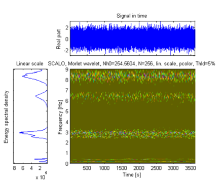
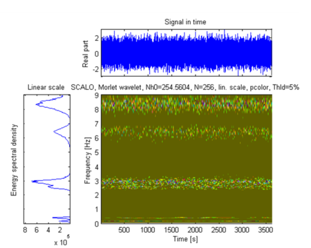
Figures 3 and 4 show the stationary sensor recorded signal time history along with its scalogram, and the mobile sensor recorded signal time history traveling at 0.0167 m/s along with its scalogram, respectively.
|
| Figure 3. Stationary sensor recorded signal: time history, energy spectral density and Scalogram |
|
| Figure 4. Mobile sensor recorded signal: time history, energy spectral density and Scalogram |
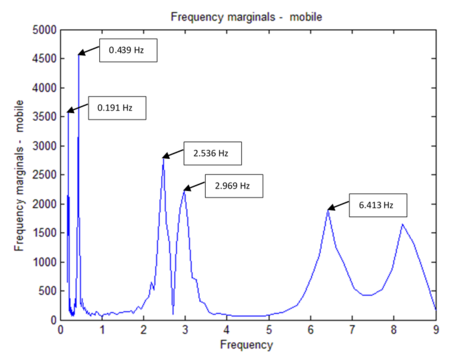
Modal frequencies obtained by selecting peaks (Figure 5); damping ratios obtained using the stationary sensor signal scalogram [1]; mode shapes obtained using the response signals wavelet transforms via Eqs.(6) and (7); comparison made between the identified and the exact mode shapes; in this example 59 modal coordinates were identified.
|
| Figure 5. Mobile sensor frequency marginals (i.e. natural rrequencies) |
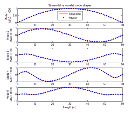
Comparative results performed from the numerical simulation and the theoretical example; identified mode shapes compared to the exact mode shapes using the Modal Assurance Criterion (MAC) [31] (Figure 6); damping ratio identified using technique identification by Le [1]; The Time-Frequency Toolbox software (TFTB) used for the wavelet signals processing [29,32]. Table 1 summarizes the results of the modal parameter identification. As shown, the errors in natural frequencies are less than 1.6%, the maximum modal damping error is 10.0 %, and MAC values are all very close to 1.0.
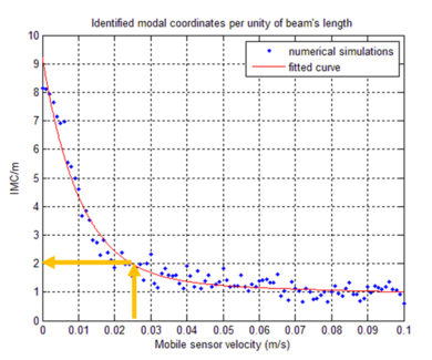
In Figure 7, the axis is the mobile sensor’s velocity. The Y axis is the variations in the Identified Modal Coordinates (IMC) per beam’s length unit. Two modes are considered correlated when the MAC value is at least equal to 0.95, corresponding to 18 degrees angle [31]. For instance, if the speed of the mobile sensor is 0.024 m/s, its correspondent IMC is 2 (Identified Modal Coordinates per meter).
|
| Figure 6. Identified mode shapes |
| MODE | Theoretical frequencies (Hz) |
Identification by wavelets | Frequency error (%) |
Damping error (%) | ||
|---|---|---|---|---|---|---|
| Natural frequencies (Hz) | Damping ratios | MAC values | ||||
| 1 | 0.194 | 0.191 | 0.047 | 1.000 | 1.546 | 6.000 |
| 2 | 0.435 | 0.439 | 0.046 | 0.999 | 0.920 | 8.000 |
| 3 | 2.511 | 2.536 | 0.055 | 0.999 | 0.996 | 10.000 |
| 4 | 2.961 | 2.969 | 0.053 | 0.998 | 0.270 | 6.000 |
| 5 | 6.491 | 6.413 | 0.052 | 0.999 | 1.202 | 4.000 |
|
| Figure 7. IMC/m values versus mobile sensor velocity |
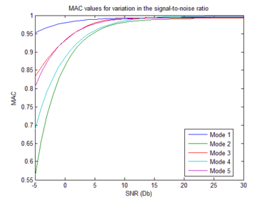
The noise influence was evaluated too. As per observable in Figure Figure 8, signal-to-noise ratio, results for values greater than lie very close to 1 (MAC value). Such good identification results were obtained from the simulated ambient contaminated response data.
|
| Figure 8. MAC values and signal-to-noise ratio variation. (first five identified modes) |
4. Experimental validation
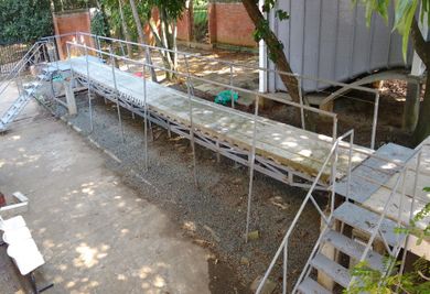
The above presented procedure is applied to acceleration responses on a pedestrian bridge, at Universidad del Valle, Cali, Colombia. The bridge structure is a simply supported steel truss on concrete frames as shown in Figure Figure 9. The bridge superstructure has 12 m span and 1.2 m width. Its mass and effective flexural rigidity are approximately uniform over the entire span. The mass is about 310 kg/m.
The setup (Figure 10), a mobile sensing platform (Figure 11) and a stationary sensor (Figure 12) located 5 meters from the support. Forced vibration tests carried out using white noise input. Vertical acceleration response along the axis of the bridge measured and recorded via a mobile sensing accelerometer and a 16-bits data acquisition system.
|
| Figure 9. Pedestrian bridge |

|
| Figure 10. Mobile sensing setup |

|
| Figure 11. Mobile sensing platform |

|
| Figure 12. 1-Axis accelerometer module |
One g 130 dB (at 1 Hz) triaxial accelerometer and three g /Hz uniaxial accelerometers were used. Four configurations were used for a total of 11 equidistant points along the deck axis. Vertical acceleration: sets of 100 samples/s, 5 minutes recording time. Response signals processed via Stochastic Subspace Identification (SSI) technique [33].
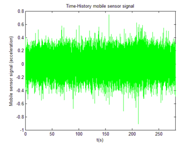
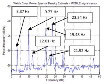
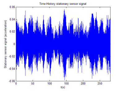
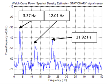
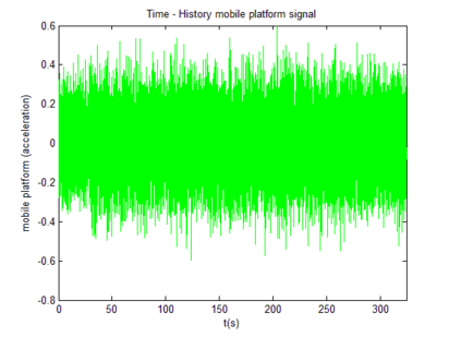
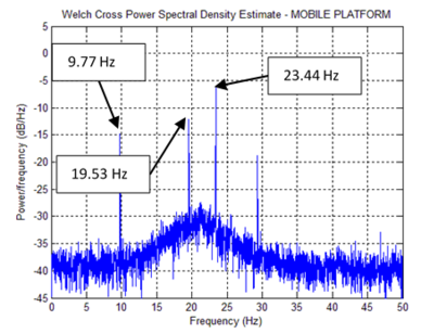
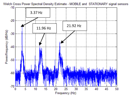
Figure 9 shows the process with the mobile sensing setup. Firstly, the mobile platform frequency was individually identified (Figure 13). Then the mobile sensor set was put to travel along the bridge axis at . Both sensors, the mobile and the stationary, achieved a sampling rate of . The white noise input was supplied from a shaker, and the recording time was . With all Response Signals available the fundamental frequencies were extracted from the peaks of each PSD graph (Figure 14), and, finally, a Crossed PSD (CPSD) used to clear off process alien peaks (15).
|
|
| (a) Time history - Mobile platform signal | (b) PSD – mobile platform signal |
| Figure 13. Mobile platform record | |
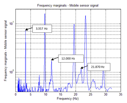
Table 2 summarizes the identified frequencies from Figures 13, 14 and 15. Figure 16, the mobile sensor signal marginals, its peaks show the fundamental frequencies, extracted via Eq.(10). Modal Identification performed via Eqs.(6) and (7) and Damping Ratios obtained using [1]. Table 3 is a comparative table between SSI results (stationary sensor dynamic identification) and time-scale based identification results (mobile sensor dynamic identification).
| Identified Element | Mobile Platform Hz | Mobile Sensor Hz | Stationary Sensor Hz | Stationary- Mobile Sensors Hz |
|---|---|---|---|---|
| (Figure 13) | (Figure 14b) | (Figure 14d) | (Figure 15) | |
| Bridge | --- | 3.37 | 3.37 | 3.37 |
| Platform | 9.77 | 9.77 | --- | --- |
| Bridge | --- | 12.01 | 12.01 | 11.96 |
| Platform | 19.53 | 19.48 | --- | --- |
| Bridge | --- | 21.92 | 21.92 | 21.92 |
| Platform | 23.44 | 23.34 | --- | --- |
|
| Figure 15. PSD - stationary-mobile signals (CPSD) |
|
| Figure 16. Marginals mobile sensor signal |
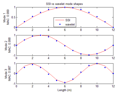
Estimations of modal frequencies were obtained from the marginal peaks (Figure 16). Estimated modal frequencies via Wavelets were notoriously close to those found through SSI, showing a maximum error of 0.811%. Mode shapes were identified through Eqs.(6) and (7). MAC values found notoriously close to 1.00 (Figure 17).
| DYNAMIC IDENTIFICATION (MOBILE SENSORS – STATIONARY SENSORS) | |||||||
|---|---|---|---|---|---|---|---|
| MODE | SSI | WAVELETS | Frequency diff. | Damping diff. | |||
| f (Hz) | ζ (%) | f (Hz) | ζ (%) | MAC | % | % | |
| 1 | 3.330 | 0.720 | 3.357 | 0.840 | 0.999 | 0.811 | 16.667 |
| 2 | 11.920 | 0.350 | 12.000 | 0.240 | 0.998 | 0.671 | 31.428 |
| 3 | 21.740 | 0.900 | 21.870 | 0.910 | 0.988 | 0.598 | 1.111 |
|
| Figure 17. Identified mode shapes, wavelets versus SSI |
5. Conclusions
This paper shows the simplicity, exactness and effectiveness of using mobile sensors setups in determining structural dynamic properties, carried out under normal operation.
The technique proved its usefulness for high spatial resolution mode shape identification. Given the time and frequency variability nature of the signals, they were processed via a time-scale analysis, i.e. the Continuous Wavelet Transform (CWT). For the simulation case, five vertical closed mode shapes were identified from the mobile and stationary sensors data using the technique outlined in this document. When SNR is greater 15 dB, acceptable MAC values are obtained. The mobile sensor velocity influence was evaluated too. Acceptable results are obtained for velocities less than .
An experimental test was carried out to validate the methodology with a pedestrian bridge. The results of the proposed methodology were compared with the mode shapes obtained from a modal identification procedure using stationary sensors. A mobile sensor was built to collect data in motion while a reference sensor remained stationary. The mobile sensor consists of a platform with a 1-Axis Accelerometer Module (MEMS type). The mobile sensor velocity was . Eleven vertical modal coordinates were identified for the first three modes shapes using signals recorded by the mobile sensor and the stationary sensor. MAC values of 0.999, 0.998 and 0.987 were obtained between the modes identified using the SSI technique and the based Time - Scale technique. Four configurations with stationary sensors were required to identify eleven modal coordinates.
Acknowledgements
The authors wish to thank Universidad del Valle and Universidad del Quindío in Colombia, for their support on the research.
References
[1] Le T-P. Use of the Morlet mother wavelet in the frequency-scale domain decomposition technique for the modal identification of ambient vibration responses. Mech. Syst. Signal Process., 95:488–505, 2017.
[2] Sun Z., Hou W., Sun L.M. Close-Mode identification based on wavelet scalogram reassignment. Presented at the 2006 IMAC-XXIV: Conference & Exposition on Structural Dynamics, 2006.
[3] Abdelgawad A., Yelamarthi K. Structural health monitoring: Internet of things application. Proceedings in IEEE 59th International Midwest Symposium on Circuits and Systems (MWSCAS), 1:4, 2016.
[4] Zhang L., Wang T., Tamura Y. A frequency–spatial domain decomposition (FSDD) method for operational modal analysis, Mech. Syst. Signal Process. 24:1227–1239, 2010.
[5] Marulanda J., Caicedo J. M. Thomson P. Modal identification using mobile sensors under ambient excitation. J. Comput. Civ. Eng., 31:04016051, 2016.
[6] Marulanda J. Modal identification using smart mobile sensing units. Programa Editorial Universidad del Valle, Cali-Colombia, 2014.
[7] Matarazzo T. J., Horner, Pakzad S. N. High-Resolution mode shape identification using mobile sensors. Topics in Modal Analysis & Testing, 10:255-260, 2016.
[8] Valeti B., Matarazzo T. J., Pakzad S. N., Experimental study on wireless mobile sensor configurations for output-only modal identification of a beam testbed. Sensors and Instrumentation, 5:71-77, 2017.
[9] Zhu D., Yi X., Wang Y., Lee K-M., Guo J. A Mobile sensing system for structural health monitoring: design and validation. Smart Mater. Struct., 19:5:1-11, 2010.
[10] Zhu D., Guo J., Cho C., Wang Y., Lee K-M. Wireless mobile sensor network for the system identification of a space frame bridge. IEEEASME Trans. Mechatron., 17:499–507, 2012.
[11] James G. H. I., Carne T. G., Lauffer J. P. The Natural excitation technique (NEXT) for modal parameter extraction from operating wind turbines. The International journal of analytical and experimental modal analysis, 10:260-277, 1995.
[12] Yang Y. B., Lin C. W., Yau J. D. Extracting bridge frequencies from the dynamic response of a passing vehicle. J. Sound Vib., vol. 272:471–493, 2004.
[13] Lin C. W., Yang Y. B. Use of a passing vehicle to scan the fundamental bridge frequencies: An experimental verification. Eng. Struct., 27:1865–1878, 2005.
[14] Yang Y. B., Chang K. C. Extracting the bridge frequencies indirectly from a passing vehicle: Parametric study. Eng. Struct., vol. 31:2448–2459, 2009.
[15] Siringoringo D. M., Fujino Y. Estimating bridge fundamental frequency from vibration response of instrumented passing vehicle: Analytical and experimental study. Adv. Struct. Eng., 15:417–433, 2012.
[16] González A., OBrien E. J., McGetrick P. J. Identification of damping in a bridge using a moving instrumented vehicle. J. Sound Vib., 331:4115–4131, 2012.
[17] Li J., Zhu X., Law S, Samali B. Indirect bridge modal parameters identification with one stationary and one moving sensors and stochastic subspace identification. J. Sound Vib., 446:1–21, 2019.
[18] Matarazzo T. J., Pakzad S. N. Structural identification for mobile sensing with missing observations. J. Eng. Mech., 142, 2016.
[19] Staszewski W. J. Identification of damping in mdof systems using time-scale decomposition. J. Sound Vib., 203:283–305, 1997.
[20] Ruzzene M., Fasana A., Garibaldi L., Piombo B. Natural frequencies and dampings identification using wavelet transform: Application to real data. Mech. Syst. Signal Process., 11:207–218, 1997.
[21] Kijewski T. Kareem A. Wavelet transforms for system identification in civil engineering. Comput.-Aided Civ. Infrastruct. Eng., 18:339–355, 2003.
[22] Chakraborty A., Basu B. Nonstationary response analysis of long span bridges under spatially varying differential support motions using continuous wavelet transform. J. Eng. Mech., 134, 2008.
[23] Yan W. J., Ren W. X. Use of continuous-wavelet transmissibility for structural operational modal analysis. J. Struct. Eng., 139:1444–1456, 2013.
[24] Le T-P., Paultre P. Modal identification based on the time–frequency domain decomposition of unknown-input dynamic tests. Int. J. Mech. Sci., 71:41–50, 2013.
[25] Pan X., Shang F., Yuan S. Wavelet-based electromechanical mode shape online identification from ambient data. Proceedings in 4th International Conference on Electric Utility Deregulation and Restructuring and Power Technologies (DRPT), 1841–1847, 2011.
[26] Pan X., Venkatasubramanian V. Multi-dimensional wavelet analysis for power system oscillation monitoring using synchrophasors, Proceedings in IEEE PES Innovative Smart Grid Technologies (ISGT), 1–10, 2012.
[27] Bronzini M., Bruno S., Benedictis M. D., Scala M. L. Power system modal identification via wavelet analysis, ¨Proceedings in IEEE Lausanne Power Tech, 2041–2046, 2007.
[28] Staszewski W. J., Wallace D. M. Wavelet-based frequency response function for time-variant systems—An exploratory study. Mech. Syst. Signal Process. 47-1–2:35–49, 2014.
[29] Auger F., Flandrin P., Goncalves P., Lemoine O. Time-Frequency Toolbox For Use with MATLAB Tutorial. Centre National de la Recherche Scientifique, 1996.
[30] Rioul O., Flandrin P. Time-scale energy distributions: a general class extending wavelet transforms. IEEE Trans. Signal Process., 40-7:1746–1757, 1992.
[31] Pastor M., Binda M., Harčarik T. Modal assurance criterion. Procedia Eng., 48:543–548, 2012.
[32] Auger F., Flandrin P., Goncalves P., Lemoine O. Time-Frequency Toolbox For Use with MATLAB Reference Guide. Centre National de la Recherche Scientifique, 1996.
[33] Brincker R. and Andersen P. Understanding stochastic subspace identification. Proceedings in 24th IMAC St Louis Mo., 2006.
Document information
Published on 22/01/20
Accepted on 06/12/19
Submitted on 22/08/19
Volume 36, Issue 1, 2020
DOI: 10.23967/j.rimni.2019.12.002
Licence: CC BY-NC-SA license
