Abstract
This work is focussed on the numerical modeling of mixed convection heat transfer effects in a lid-driven cavity filled with a copper–water nanofluid. A heated wall mounted block with constant heat flux is attached along the vertical wall. The left vertical wall is maintained at higher temperature compared to the right vertical wall and the other (top and bottom) walls are insulated. A finite volume based numerical approach with QUICK scheme is used for the solution of nonlinear governing equations. A computational visualization technique is used to represent the two dimensional results of streamlines, isotherms, average Nusselt number and bulk-average temperature for a wide range of physical parameters, namely Reynolds number, Rayleigh number and solid volume fraction. The effective fluid flow and heat transfer variation are analyzed by placing the heated mounted block first along the left vertical wall (Case-I) and then along the right vertical wall (Case-II) to test the maximum heat transfer effects. The changes in main characteristics of the flow due to variation of Reynolds number and Rayleigh number are elaborated. The effect of various flow parameters on the thermal conductivity behavior for both cases is discussed based on average Nusselt number and bulk-average temperature and found that Case-I shows higher heat transfer rate compared to Case-II, for higher and .
Keywords
Nanofluid; Mixed convection; Bulk-average temperature; QUICK scheme
Nomenclature
- specific heat capacity (J/K)
Gr- Grashof number
g- gravitational acceleration ()
k- thermal conductivity (W/m K)
Pr- Prandtl number
Ra- Rayleigh number
Re- Reynolds number
Ri- Richardson number
T- temperature (K)
- dimensionless temperature
- Cartesian coordinates (m)
- dimensionless Cartesian coordinates
- components of velocity in and directions ()
- dimensionless of velocity components in x and y directions
H- height of cavity (m)
W- width of cavity (m)
Greek letters
- stream function ()
- dimensionless stream function ()
- vorticity ()
- dimensionless vorticity ()
- thermal diffusivity () ()
- coefficient of volume expansion ()
- solid volume fraction
- dynamic viscosity (Pa s)
- kinematics viscosity ()
- density ()
Subscripts
- fluid
- average
- nanofluid
- reference state
- solid
- wall
- cold
1. Introduction
In recent years, nanofluids have attracted enormous interests from researchers due to their large scale applications in industry, power plants and reactors for cooling processes. Normally fluids such as water, propylene glycol or ethylene glycol are used for cooling process but these compounds possess very low thermal conductivity. The term nanofluid refers to the fluid in which nanoscale particles are suspended in the base fluid to utilize their suspension stability effectively [1]. Metallic nanoparticles with high thermal conductivity lead to remarkable increase in effective thermal conductivity of these types of fluids. However, the increase in the thermal conductivity depends on shape and size of the solid nanoscale particles. The scalar transport properties can also be enhanced considerably by adding these particles to liquid flow. The dependence of thermophysical properties in nanoparticles-fluid mixture is estimated by Xie et al. [2]. They found that nanoparticle fluid mixtures containing nano-sized particles have high thermal conductivity compared to the same liquid without nanoparticles. Keblinski et al. [3] worked on the possible mechanisms of enhancing thermal conductivity and suggested that the size effect, the surface absorption and clustering of nanoparticles could be the major reasons for heat transfer enhancement. The model developed by Maxwell [4] has shown that effective thermal conductivity of suspensions containing spherical particles can be increased by increasing the solid volume fraction of the nanoparticles. The proposed model also depicted the dependence of thermal conductivity of nanofluid on the solid volume fraction ratio which is applicable to only micro sized particles with low dense mixtures. Consequently, Maxwell’s model is improved by the number of authors, e.g. Kumar et al. [5], Patel et al. [6], Yu and Choi [7] and Prasher et al. [8] by varying the particle size, solid volume fraction ratio and temperature to find the higher thermal conductivity.
In the natural convection process, it is found that dynamic viscosity plays a vital role for heat transfer enhancement of the nanofluid. Xu et al. [9] proposed a model for calculation of the thermal conductivity of nanofluids, due to Brownian motion of nanoparticles in the base fluid depending upon average size of nanoparticles, temperature, fractal dimensions and concentration of nanofluids. Sheremet and Pop [10] studied a steady natural convection in a square porous enclosure filled with nanofluid by using Buongiorno’s model. Two vertical side walls are used as heat source for the convection heat transfer and Darcy’s law for the flow in the porous medium and the Boussinesq approximation for the buoyancy effects. It is observed that high thermophoresis parameter, low Brownian motion parameter, low Lewis and Rayleigh numbers and high thermal conductivity ratio reflect essential non-homogeneous distribution of the nanoparticles inside the porous cavity.
Eastman et al. [11] experimentally observed that thermal conductivity can be increased up to 60% by using a nanofluid consisting of water and 5% CuO nanoparticles. Khanafer et al. [12] conducted a numerical study of natural convection utilizing copper–water nanofluid in a two-dimensional enclosure. They found that for any Grashof number, heat transfer in the enclosure is increased by changing the volume fraction of copper nanoparticles in water. Lee et al. [1] experimentally observed that thermal conductivity of nanofluids increases with the increase in solid volume fraction by considering both –water and CuO–water mixture. Ho et al. [13] numerically investigated the effects of uncertainties due to adopting various formulae for the effective thermal conductivity and dynamic viscosity of the –water nanofluid in a vertical square enclosure. It is also found that by adding nanoparticles in pure water improves its cooling performance at low Rayleigh numbers. Mixed convection flow in lid-driven cavity with a horizontal sliding wall is a subject of interest for many years since this phenomenon often affects the thermal performance of the system. Khanafer et al. [12] investigated the problem of buoyancy-driven heat transfer enhancement of nanofluids in a two-dimensional enclosure by a natural convection process where the vertical walls are maintained at high and low temperature and other walls are insulated, non-conducting and impermeable to mass transfer. Heat transfer performance is discussed based on the buoyancy effects, solid particle dispersion and various flow controlling parameters. Hwang et al. [14] carried out a theoretical investigation of the thermal characteristics of natural convection of an alumina-based nanofluid in a rectangular cavity heated from below using Jang and Choi’s model [15] by predicting the effective thermal conductivity of nanofluids. Tiwari and Das [16] investigated numerically heat transfer augmentation in a lid-driven cavity filled with a nanofluid and found that the presence of nanoparticles in base fluid is capable of increasing the heat transfer capacity. Sheremet et al. [17] also used the model suggested by Tiwari and Das and discussed the natural convection heat transfer in a porous enclosure utilizing nanofluid in conditions of thermal stratification. They have tried to find the effects of Rayleigh number, thermal stratification parameter, porosity of the porous medium, solid volume fraction parameter of nanoparticles, and the solid volume fraction on the local and average Nusselt numbers, streamlines and isotherms. A mixed convective heat and mass transfer effects in a lid driven cavity are studied by Sheremet and Pop [18]. The movable upper and lower lids are maintained with higher and lower temperature to find the substantial effects on the flow and heat transfer characteristics due to variation of the Reynolds, Grashof, Prandtl and Lewis numbers along with the buoyancy-ratio. Study of laminar mixed convective flow and heat transfer of water with nanofluid in single and double lid-driven cavities is carried out by Chamkha and Abu-Nada [19]. They reported about the heat transfer enhancement due to nanoparticles volume fraction for moderate and large Richardson numbers. According to Nasrin et al. [20] Richardson number plays a vital role on the heat transfer characterization. The technique for improving thermal conductivity by using nanofluids in place of traditional fluids such as water has been extensively used nowadays. The most usage of mixed convection flow with lid-driven effect is to include the electronic cooling, MEMS applications, food processing, nuclear reactors, drying technologies and lubrication technologies [21] and [22].
Despite a good number of theoretical and experimental works on nanofluid based on buoyancy driven natural or mixed convection process heated from side or bottom wall are analyzed in the literature, still there are several information lacking regarding the heat transfer enhancement in enclosures. To the best of our knowledge, the problem of mixed convection cavity due to buoyancy driven flow with a localized heat source along the vertical walls in enclosures is not reported in the literature. The problem is of significance in a number of electronic cooling equipped with nanofluids.
The present work focusses on the effective heat transfer and its variation due to the localized heat source embedded along the left and right vertical walls of the lid driven cavity filled with copper–water nanofluid since Khorasanizadeh et al. [23] found that the maximum heat conductivity can be found by differentially heated walls. Effective thermal conductivity mapping is analyzed for a wide range of pertinent parameters, such as Reynolds number, Rayleigh number and solid volume fraction.
2. Problem definition and mathematical formulation
2.1. Physical configuration
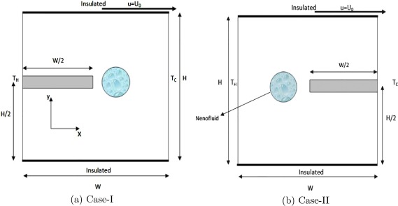
In the present study a two dimensional enclosure of height ‘’ and width ‘’ filled with a suspension of copper nanoparticles in water is considered. The top and bottom walls are assumed to be nonconducting, insulated and impermeable to solute. The left vertical wall is kept at high temperature () and right vertical wall is maintained with low temperature (). The copper nanoparticles are assumed to be of uniform shape and size and diameter is equal to be 100 nm. A heat source with constant heat flux of length is attached along the vertical wall. Case-I is for the heat source placed along the left vertical wall above the height (Fig. 1(a)), and Case-II is for the heat source placed along the right vertical wall above the height (Fig. 1(b)). The copper–water nanofluid is assumed to be Newtonian, incompressible and laminar. It is assumed that the fluid phase and nanoparticles both are in thermal equilibrium state and have same velocity with no slip condition. The thermophysical properties of the nanofluid are assumed to be constant except for the density variation which is determined using Boussinesq approximation [24]
|
|
(1) |
where is the density of undisturbed fluid, is the uniform temperature of the fluid at rest. The volumetric coefficient of thermal expansion is
|
|
(2) |
|
|
|
Figure 1. A schematic diagram of the physical model. |
The thermophysical properties of water and copper at the reference temperature are presented in Table 1.
| Property | Water | Copper |
|---|---|---|
| 4179 | 383 | |
| 997.1 | 8954 | |
| k | 0.6 | 400 |
The two dimensional governing Navier–Stokes equations along with heat transfer equation in stream function–vorticity formulation in dimensional form with Boussinesq-fluid assumption are given by.
Kinematics equation:
|
|
(3) |
Vorticity equation:
|
|
(4) |
Energy equation:
|
|
(5) |
where is the thermal diffusivity. The effective density of nanofluid at the reference temperature can be defined as
|
|
(6) |
where and are the density of nanofluid, density of base fluid, density of nanoparticle and volume fraction of the nanoparticles, respectively.
The heat capacitance of nanofluid can be written as
|
|
(7) |
The effective thermal conductivity of the nanofluid is approximated by the Maxwell self-consistent approximation model. For the two-component entity of spherical-particle suspension, the Maxwell model [4] gives
|
|
(8) |
The effective viscosity of nanofluid is given by Brinkmann [25] as follows,
|
|
(9) |
The initial and boundary conditions are given by
|
|
(10) |
for ,
|
|
|
|
|
|
|
|
(11) |
At the heat source surface; .
The above mentioned equations can be expressed in non-dimensional form by incorporating the following dimensionless variables,
|
|
(12) |
The governing equations in dimensionless form by considering the above mentioned assumptions can be rewritten as,
|
|
(13) |
|
|
(14) |
|
|
(15) |
The initial conditions for are given by,
|
|
(16) |
and for ,
|
|
|
|
|
|
|
|
(17) |
Along the heat source surface, we have considered non-dimensional heat transfer values as, .
It can be seen from the equations that the flow and heat transfer are characterized by three dimensionless parameters (i) Rayleigh number (Ra), (ii) Reynolds number (Re) and (iii) Prandtl number (Pr) and are given by
|
|
(18) |
In order to calculate the heat transfer enhancement, we have calculated Nu (Nusselt number) and (average Nusselt number) along the heated surface as,
|
|
(19) |
|
|
(20) |
The bulk average temperature defined by Singh and Sharif [26] as,
|
|
(21) |
where V is the enclosure volume.
2.2. Numerical method
In order to obtain the numerical solution of the governing fluid flow equations together with the specified boundary conditions a control volume approach is opted [27]. The numerical solutions in this paper are obtained by choosing uniform grid system for computation. The algebraic finite volume equations for vorticity and energy are solved using alternate direction implicit (ADI) scheme. When flow is dominated by convection effects then the numerical instability is achieved for higher Reynolds number. To overcome such instability a third order accurate (QUICK) scheme is employed to discretize the convective terms [28]. The implicit scheme is used for time steps. In order to linearize the nonlinear system of partial differential equations, a quasi-linearization approximation has been employed.
At every time step, we approximate the nonlinear term as
|
|
(22) |
with , is the iteration index. The convective terms are discretized by third-order accurate upwind difference scheme given by
|
|
(23) |
for positive and,
|
|
(24) |
for negative.
The truncation error of this scheme is given by
|
|
(25) |
The expression for , near the wall is obtained by a second order central difference scheme as,
|
|
(26) |
The diffusion terms are discretized through a second-order accurate central-difference scheme, which is conducive to a stable solution as,
|
|
|
|
The vorticity boundary on the solid boundary is unknown which can be evaluated by using the Poisson Eq. (13) along the boundary. The boundary condition of wall vorticity on the lower flat surface is given by
|
|
(27) |
In a similar manner, boundary conditions for are obtained on the other walls.
We consider the grids (),
|
|
(28) |
|
|
(29) |
where i and j are grid index in the x and y directions respectively. M and N are the number of grid points along x and y directions respectively. The increment along x axis is and along y axis is . The value of and at (i, j ) cell is denoted by and respectively.
An implicit calculation of the momentum and energy equations is performed. The discretization of the governing vorticity and heat transfer equations in horizontal direction results in a system of algebraic equations of the form
|
|
(30) |
where denotes and and the coefficients for different cases are given by,
- Case-I: When
|
|
|
|
|
|
|
|
- Case-II: When
|
|
|
|
|
|
|
|
- Case-III: When
|
|
|
|
|
|
|
|
- Case-IV: When
|
|
|
|
|
|
|
|
and on the boundary the coefficients are slightly different as the convective terms are discretized by using central difference scheme. The coefficients are given by,
|
|
|
|
|
|
|
|
The vertical direction scheme is developed in the similar fashion.
The second order Poisson equation for the stream function Eq. (13), is discretized through a upwind spatial difference scheme.
The resulting algebraic equations are solved using the successive over relaxation (SOR) method. SOR method is used due to the nonlinear nature of governing equations. The convergence criterion used for the calculation of temperature, vorticity and stream function is defined by the expression,
|
|
(31) |
where is the tolerance in any time level and represents the flow variables.
The velocity components u and v at every grid point are evaluated using central difference approximation. A time dependent numerical solution is achieved by obtaining the flow field variables through a sequence of shorter time steps of duration 0.001. For the range of parameter values considered here, the flow field achieves a steady state after a transient state, and this steady state is independent of the initial conditions prescribed. To test the accuracy of our numerical algorithm, a two dimensional lid driven cavity filled with copper–water nanofluid is considered. For this structure non-dimensional governing equation involves Reynolds, Rayleigh and Prandtl number. The grid independence tests are performed by varying the grid sizes between and . Fig. 2(a) and (b) represent the grid size effect on the horizontal and transverse velocity. Fig. 2(a) represents u-velocity profile for with . We found that the solution changes by halving the grid size occurring on the third decimal place. Fig. 2(b) represents v -velocity profile for with . The comparison of our result with that of Muthtamilselvan et al. [29] is found to be optimum for grid size. A comparison of our results for streamlines with the result due to Amir et al. [30] is presented in Fig. 3(a) and (b) with and . Amir et al. considered the natural convection in a square cavity filled with nanofluid where a horizontal heat source is mounted along the left wall. It is found that the present numerical result is validated with their result up to 98%.
|
|
|
Figure 2. Comparison of the present results of (a) u-velocity with Farhad et al. [21], (b) v-velocity with Muthtamilselvan et al. [29] and (c) time step independence test at and for plain fluid. |
|
|
|
Figure 3. Comparison of streamlines with Amir et al. [30] (a) result due to Amir et al. [30] and (b) the present result where the flow parameters considered as and . |
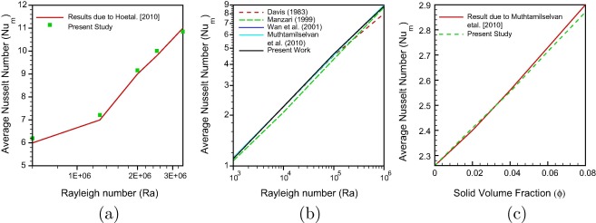
In Fig. 4(a) we present a comparison of our result for average Nusselt number of nanofluid within a vertical square enclosure with the experimental result due to Ho et al. [31]. In their experimental observation nanofluid has been formulated by mixing water with various volumetric fractions of alumina () nanoparticles ranging from 0.1 vol% to 4 vol%. The square enclosure is differentially heated across two vertical walls, while the remaining walls are thermally insulated. In the present comparison, we have considered the particle fraction as 1%, and Ra is varied as . The results obtained by Ho et al. [31] are in excellent agreement with our results.
|
|
|
Figure 4. Average Nusselt number comparison with Rayleigh number (a and b) and solid volume fraction (c). |
Fig. 4(b) represents the comparison of the present result for some special cases with the results due to Davis [32], Manzari [33], Wan et al. [34], Muthtamilselvan et al. [29], for a clear fluid case with the variation of Rayleigh numbers between with . It can be observed that the computational code is in good agreement with the benchmark results. Further, the code is validated against the result of heat transfer enhancement in a lid driven enclosure filled with copper–water nanofluid (Fig. 4(c)). The results have been presented for variation of average Nusselt number due to the uniformly heated wall where the parameters are considered as and aspect ratio = 1 with the variation of solid volume fraction . Fig. 4(c) shows the average Nusselt number comparison with Muthtamilselvan el al. [29], which seems to be in good agreement with the present solution.
3. Results and discussion
In the present study pertaining to Cu–water nanofluid the numerical computations are performed for , and and throughout the study Prandtl number is fixed. The mathematical formulation shows that the heat transfer process is mostly affected by the wall mounted heat source on the left and right vertical wall independently. The flow is governed by two mechanisms: (i) shear force due to sliding top lid and (ii) Buoyancy force due to vertical temperature gradient from left wall.
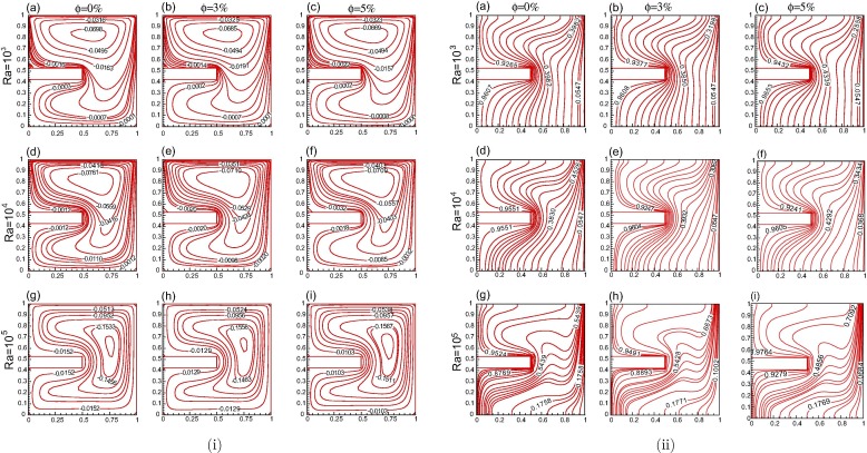
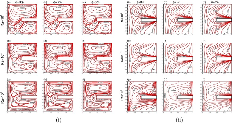
The first phase of the work deals with the heated block on the left hot wall (Case I). Fig. 5(i) and (ii) display the streamlines and isotherms for for different solid volume fractions and Rayleigh numbers. The fluid close to the heat source gets heated quickly due to quick absorption of heat. The fluid particles move upward due to buoyancy force. Then cold fluid enters to this empty region moving from near region of the right cold wall. The hot fluid is moving toward the right wall. A big recirculation zone is formed throughout the cavity. In Fig. 5(i) for , it is found that a small recirculating eddy is formed along the upper region of the cavity. The volume fraction is varied from 0% to 5%. The combined effect of weak buoyancy and shear force leads to a weak force. With increase in Rayleigh number, the position of the center of vortex moves toward right vertical wall as depicted in Fig. 5(i). The presence of nanoparticles in the water increases the intensity of the flow combined with the buoyancy and shear force. As the volume fraction value increases, the vortex move downward. Fig. 5(ii) represents the effective thermal conductivity for small Reynolds number with different Ra and values. For low values, it is observed that isotherms remain uniform in most part of cavity which signifies that heat transfer conductivity dominates. As Ra increases, the convective heat transfer effect increases and hence variation of temperature lying within the core of the cavity increases. At , it is found that the isotherms are almost parallel to the horizontal wall at the lower section of the cavity. From Fig. 5(ii)(g–i), it is observed that cold fluid is coming down along the vertical wall, touching the lower part of the heat source and then tries to get connect to the heated wall. It signifies that the temperature of the heated surface and adjacent fluid of the heat source is higher than other walls. It is also clear from the figure that the value of isotherms increases with increase in solid volume fraction ratio as well as Rayleigh number and reaches its maximum value i.e., 0.9764 for and %.
|
|
|
Figure 5. Solid volume fraction and Rayleigh number effects for Re = 10 (Case-I) (i) streamline and (ii) isotherms. |
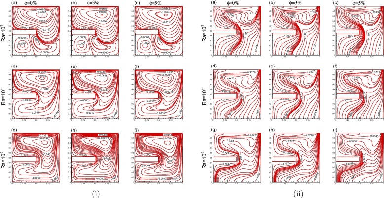
The streamlines for and are presented in Figs. 6(i) and 7(i). As Re increases, for small Ra the flow is dominated by buoyancy effects and the impact of shear mechanism generated by the moving top lid penetrates to a small distance toward the interior region of the cavity forming a primary eddy. From Figs. 6(i) and 7(i) it can be observed that two smaller eddies are formed along the lower part of the cavity. For larger Re values three eddies are generated at . It can also be observed from Fig. 7(i) that for , the lower right eddy is much larger as compared to the lower left eddy because of dominating buoyancy effect and as Ra increases it gets smaller and finally for it gets vanished because of dominating tendency of shear force. The hot fluid tries to move toward the right wall and the core fluid gets mixed at these higher Re values. At higher Reynolds number the fluid is well mixed and buoyancy force is dominated by shear force along the upper part of the cavity. It is evident from the figure that streamlines values are increasing significantly as Re increases. A regular increase in effective thermal conductivity can be seen in Figs. 6(ii) and 7(ii). The isotherm values continuously increase with increase in Ra as well as values. For the larger Re and smaller Ra values the isotherms in the upper portion of the cavity become parallel to the horizontal axis because of the effect of increasing shear force whereas in the lower portion of the cavity shear force they are less effective; hence, the isotherms are perpendicular to horizontal axis. As Ra increases, the convective heat transfer increases and hence variation of temperature lying within the core of the cavity also increases because of which the shear force dominates and hence most of the isotherms become parallel to horizontal axis.
|
|
|
Figure 6. Solid volume fraction and Rayleigh number effects for Re = 50 (Case-I) (i) streamline and (ii) isotherms. |
|
|
|
Figure 7. Solid volume fraction and Rayleigh number effects for Re = 100 (Case-I) (i) streamline and (ii) isotherms. |
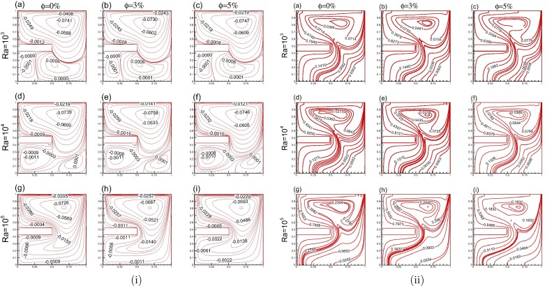
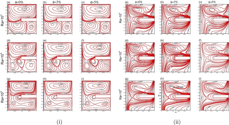
For the second case, we have kept the mounted heat source along the right wall. Fig. 8(i) represents the streamlines for with and %. For low Re values, it is found that four separate eddies form inside the cavity for smaller Ra () values (Fig. 8(i)(a–c)) and the fourth eddy vanishes with increase in Ra values. Upper eddy is formed because of the shear force due to the lid dragging the adjacent fluid. With the increase in Ra values the upper eddy starts moving toward the right side of the cavity due to increasing buoyancy effects from left wall. Middle eddy is formed due to the obstructing mounted heat source, fractional losses and stagnation pressure but it vanishes with the increasing values of Ra . The lower upstream eddy formed for is due to the combined buoyancy effects from the left wall and heat source, and got vanished as Ra increases. A lower downstream eddy is formed due to the opposing action of buoyancy. The heat transfer effects are mostly via convection in the boundary layers. The buoyancy effects are significant only near the cavity wall and core of the cavity is isothermal. With increase in Ra values, the lower downstream eddy gets enlarged and is divided into two parts due to the presence of secondary heat source along the middle of the right wall. It can be observed that the solid volume fraction does not have effect on the flow pattern but on the stream function values, the flow intensity is augmented by increasing solid volume fraction. The stream function value at the center of the cavity gets from −0.0698 to −0.0669 at for a 5% increase in solid volume fraction. Also, for smaller Ra values in Fig. 8(i)(a–c) the primary eddy adheres to the walls of the cavity, but moves away with the increasing values of Ra as shown in Fig. 8(i)(g–i), which shows that intensity on buoyancy and hence of the natural convection increases with Ra. From Fig. 8(i), it is found that the value of stream function is large at higher values of Ra as compared to lower Ra values. It is also found that due to increment of solid volume fraction the stream function values increase.
|
|
|
Figure 8. Solid volume fraction and Rayleigh number effects for Re = 10 (Case-II) (i) streamline and (ii) isotherms. |
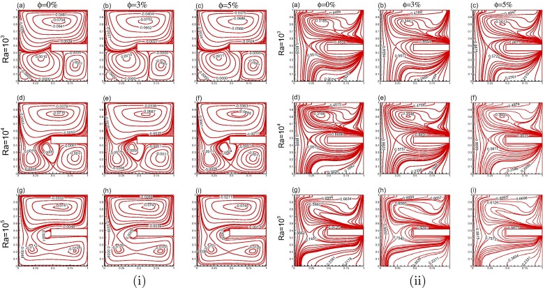
From Figs. 9(i) and 10(i), it can be predicted that increase in Re results in significant change in the flow structure, i.e., the enlargement of lower upwind eddy and subsequently contraction of lower downstream eddy. Together with this all the four eddies can be seen with increasing Ra values. But at larger Re values with larger Ra the lower downstream eddy contracts and upper eddy expands toward lower right part of cavity. We found a significant change of streamline values with increasing solid volume fraction ratio.
|
|
|
Figure 9. Solid volume fraction and Rayleigh number effects for Re = 50 (Case-II) (i) streamline and (ii) isotherms. |
|
|
|
Figure 10. Solid volume fraction and Rayleigh number effects for Re = 100 (Case-II) (i) streamline and (ii) isotherms. |
The heat transfer effect for second case has been presented in Figs. 8(ii), 9(ii) and 10(ii) for Re = 10, 50 and 100 respectively. The heat transfer for this case is due to conduction as well as convection which results in a gradual variation of temperature in the cavity. Since we have placed heat source on the right wall the fluid particles move away from heat source but at the same time the opposite wall is also hot because of which the opposing buoyancy effect takes place and the heat transfer rate increases in the whole domain. For increasing Re values, the isotherm lines become more and more parallel to the heat source. This is due to the combined effect of buoyancy and shear force due to sliding top lid. The isotherm values increase significantly with the increase in Ra values as well as with increase in solid volume fraction.
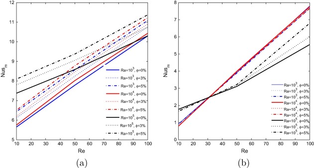
The variation of average Nusselt number against the Reynolds number (), Rayleigh number () and solid volume fraction (%) along the left vertical wall is displayed in Fig. 11 for both Case-I and Case-II. In comparison with pure fluid, use of nanofluid increases the flow intensity, gives rise to the heat transfer and hence increases average Nusselt number 11(a). The increase of Re within the cavity i.e., velocity is increased in the moving lid leads to a forced convection dominated flow which results in increment of average Nusselt number. For all Ra values, the increase in average Nusselt number seems to be linear and smooth. Increasing the value of Ra increases the average Nusselt number sharply. But increase in volume fraction values has a large impact on the heat transfer enhancement. For a particular Rayleigh number () if the volume fraction values are increasing (3–5%), the rate of heat transfer increases even if the Rayleigh number is larger in that particular volume fraction value (). The change of volume fraction values is responsible for the heat exchange between the system and nanoparticles.
|
|
|
Figure 11. Average Nusselt number along left wall for various and (a) Case-I, (b) Case-II. |
The average Nusselt number for Case-II is displayed in Fig. 11(b). In this case the average heat transfer rate is decreasing when the Ra value is increasing at low Re values. Except for the value of , the increase is linear. For higher Re (Re = 100) it is found that the highest average heat transfer is found for . The variation of average Nusselt number against volume fraction is not significant for lower Ra values. For , the average Nusselt number variation is found to be minimum. From both the cases it can be observed that higher values of heat transfer rate occurred in Case-I compared to Case-II. The use of heat source in Case-I instead of Case-II causes a greater increase in average Nusselt number such that the relative increase is 79.5% at and = 5% and 40.3% at and = 5%.
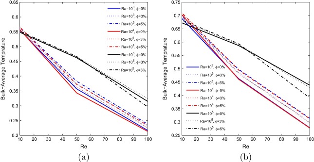
Fig. 12 represents the bulk average nanofluid temperature for Case-I and Case-II. The bulk average variation is shown against the Re. It is observed from the figure that bulk average temperature is going down when Re increases in both the cases. For all pertinent parameters Case-II represents higher bulk average temperature than Case-I. It can be clearly observed that bulk average temperature increases with increase in solid volume fraction. The profiles are sharp but not smooth. For both these cases at higher Ra values with the solid volume fraction shows negative impact on the heat transfer rate.
|
|
|
Figure 12. Bulk average temperature for various and (a) Case-I, (b) Case-II. |
4. Conclusion
This paper presents a numerical study of mixed convection flows of copper–water nanofluid in a lid driven cavity in which a heat source is mounted on a vertical wall of cavity. The mounted heat source is firstly kept on the left (hot) vertical wall and then to the right (cold) vertical wall. The left vertical wall is kept at higher temperature compared to right vertical wall and the other two horizontal walls are kept insulated. The investigation has been accomplished for the size of copper nanoparticles equal to 100 nm and for a wide range of Re and Ra with different values of solid volume concentration. In this study the effect of and on the flow pattern and heat characteristics are investigated. Based on the present results it is observed that for fixed value of Ra, the flow is dominated by the convection effects where the buoyancy-induced activities are appreciable and fluid is well mixed and temperature is well distributed in the bulk of cavity for low Re values. Under concurring thermal buoyancy forces along with the forced buoyancy effects (i.e. when Re increases), stably-stratified region becomes wider along the lower part of the cavity and the vertical temperature gradients are increased. Heat conductivity is lesser when the heat source is mounted on left side as compared to the right side. For a fixed Re , the solid volume fraction and Rayleigh number have a positive effect on heat transfer enhancement. Moreover, thermal conductivity increases with increasing Rayleigh number. The average Nusselt number is increasing with increase in and for both these cases but Case-I shows higher heat transfer rate. Also, the effect of increasing solid volume fraction is large in Case-I as compared to Case-II. In case-II, the solid volume fraction has a noticeable effect only for the larger Re and Ra values. The bulk average temperature is decreasing with increase in Re, and the bulk average temperature is higher in Case-II as compared to Case-I for all the considered parameters. The further extension of this work will be considered for larger size of nanoparticles or greater solid volume fraction as discussed by some of the recent studies [17] and [18] using two phase model for the better understanding of heat transfer in nanofluid flow in the presence of Brownian motion and thermophoresis effects. The effects of opaque wall and porosity will also be studied using different heat sources.
Acknowledgment
The first author would like to thank Ministry of Human Resource and Development with Grant No. MHR-02-23-200-429 for their funding.
References
- [1] S. Lee, S.U.S. Choi, J.A. Eastman; Measuring thermal conductivity of fluids containing oxide nanoparticles; J. Heat Transfer, 121 (1999), pp. 280–289 http://dx.doi.org/10.1115/1.2825978
- [2] H.Q. Xie, J.C. Wang, T.G. Xi, Y. Li, F. Ai; Dependence of the thermal conductivity of nanoparticlefluid mixture on the basefluid; J. Mater. Sci. Lett., 21 (19) (2002), pp. 1469–1471 http://dx.doi.org/10.1023/A%3A1020060324472
- [3] P. Keblinski, S. R Phillpot, S.U. S Choi, J. A Eastman; Mechanisms of heat flow in suspensions of nano-sized particles (nanofluids); Int. J. Heat Mass Transfer, 45 (4) (2002), pp. 855–863 http://dx.doi.org/10.1016/S0017-9310(01)00175-2
- [4] J.C. Maxwell; A Treatise on Electricity and Magnetism; (second ed.)Oxford University Press, Cambridge (1904) pp. 435–441
- [5] D.H. Kumar, H.E. Patel, V.R. Rajeev Kumar, T. Sundararajan, T. Pradeep, S.K. Das; Model for heat conduction in nanofluids; Phys. Rev. Lett., 93 (14) (2004), pp. 144301-1–144301-4 http://dx.doi.org/10.1103/PhysRevLett.93.144301
- [6] H.E. Patel, T. Pradeep, T. Sundararajan, A. Dasgupta, N. Dasgupta, S.K. Das; A microconvection model for thermal conductivity of nanofluid; Pramana – J. Phys., 65 (5) (2005), pp. 863–869 http://dx.doi.org/10.1615/IHTC13.p8.240
- [7] W. Yu, S.U.S. Choi; The role of interfacial layer in the enhanced thermal conductivity of nanofluids: a renovated Maxwell model; J. Nanoparticle Res., 5 (1–2) (2003), pp. 167–171 http://dx.doi.org/10.1023/A:1024438603801
- [8] R. Prasher, P. Bhattacharya, P.E. Phelan; Brownian-motion-based convective conductive model for effective thermal conductivity of nanofluid; ASME J. Heat Transfer, 128 (2006), pp. 588–595 http://dx.doi.org/10.1115/1.2188509
- [9] J. Xu, B. Yu, M. Zou, P. Xu; A new model for heat conduction of nanofluids based on fractal distributions of nanoparticles; J. Phys. D: Appl. Phys., 39 (20) (2006), pp. 4486–4490 http://dx.doi.org/10.1088/0022-3727/39/20/028
- [10] M.A. Sheremet, I. Pop; Conjugate natural convection in a square porous cavity filled by a nanofluid using Buongiorno’s mathematical model; Int. J. Heat Mass Transfer, 79 (2014), pp. 137–145 http://dx.doi.org/10.1016/j.ijheatmasstransfer.2014.07.092
- [11] J.A. Eastman, S.U.S. Choi, S. Li, W. Yu, L.J. Thompson; Anomalously increased effective thermal conductiveness of ethylene glycol-based nano-fluids containing copper nano-particles; Appl. Phys. Lett., 78 (6) (2001), pp. 718–720 http://dx.doi.org/10.1063/1.1341218
- [12] K. Khanafer, K. Vafai, M. Lightstone; Buoyancy-driven heat transfer enhancement in a two-dimensional enclosure utilizing nanofluids; Int. J. Heat Mass Transfer, 46 (19) (2003), pp. 3639–3653 http://dx.doi.org/10.1016/S0017-9310(03)00156-X
- [13] C.J. Ho, M.W. Chen, Z.W. Li; Numerical simulation of natural convection of nanofluid in a square enclosure: Effects due to uncertainties of viscosity and thermal conductivity; Int. J. Heat Mass Transfer, 51 (1718) (2008), pp. 4506–4516 http://dx.doi.org/10.1016/j.ijheatmasstransfer.2007.12.019
- [14] K.S. Hwang, J.H. Lee, S.P. Jang; Buoyancy-driven heat transfer of water-based Al2O3 nanofluids in a rectangular cavity; Int. J. Heat Mass Transfer, 50 (1920) (2007), pp. 4003–4010 http://dx.doi.org/10.1016/j.ijheatmasstransfer.2007.01.037
- [15] S.P. Jang, S.U.S. Choi; The role of Brownian motion in the enhanced thermal conductivity of nanofluids; Appl. Phys. Lett., 84 (2004), pp. 4316–4318 http://dx.doi.org/10.1063/1.1756684
- [16] R.K. Tiwari, M.K. Das; Heat transfer augmentation in a two-sided lid-driven differentially heated square cavity utilizing nanofluids; Int. J. Heat Mass Transfer, 50 (910) (2007), pp. 2002–2018 http://dx.doi.org/10.1016/j.ijheatmasstransfer.2006.09.034
- [17] M.A. Sheremet, S. Dinarvand, I. Pop; Effect of thermal stratification on free convection in a square porous cavity filled with a nanofluid using Tiwari and Das’ nanofluid model; Phys. E: Low-Dimens. Syst. Nanostruct., 69 (2015), pp. 332–341 http://dx.doi.org/10.1016/j.physe.2015.02.005
- [18] M.A. Sheremet, I. Pop; Mixed convection in a lid-driven square cavity filled by a nanofluid: Buongiorno’s mathematical model; Appl. Math. Comput., 266 (2015), pp. 792–808 http://dx.doi.org/10.1016/j.amc.2015.05.145
- [19] A.J. Chamkha, E. Abu-Nada; Mixed convection flow in single- and double-lid driven square cavities filled with water– nanofluid: effect of viscosity models; Euro. J. Mech. – B/Fluids, 36 (2012), pp. 82–96 http://dx.doi.org/10.1016/j.euromechflu.2012.03.005
- [20] R. Nasrin, A.J. Chamkha, M.A. Alim; Modelling of mixed convective heat transfer utilizing nanofluid in a double lid driven chamber with internal heat generation; Int. J. Numer. Methods Heat Fluid Flow, 24 (1) (2013), pp. 36–57 http://dx.doi.org/10.1108/HFF-11-2011-0239
- [21] F. Talebi, A.H. Mahmoudi, M. Shahi; Numerical study of mixed convection flows in a square lid-driven cavity utilizing nanofluid; Int. Commun. Heat Mass Transfer, 37 (1) (2010), pp. 79–90 http://dx.doi.org/10.1016/j.icheatmasstransfer.2009.08.013
- [22] S.M. Aminossadati, B. Ghasemi; Natural convection cooling of a localised heat source at the bottom of a nanofluid-filled enclosure; Euro. J. Mech. – B/Fluids, 28 (5) (2009), pp. 630–640 http://dx.doi.org/10.1016/j.euromechflu.2009.05.006
- [23] H. Khorasanizadeh, M. Nikfar, J. Amani; Entropy generation of Cu–water nanofluid mixed convection in a cavity; Euro. J. Mech. – B/Fluids, 37 (2013), pp. 143–152 http://dx.doi.org/10.1016/j.euromechflu.2012.09.002
- [24] S. Kashani, A.A. Ranjbar, M. Mastiani, H. Mirzaei; Entropy generation and natural convection of nanoparticle–water mixture (nanofluid) near water density inversion in an enclosure with various patterns of vertical wavy walls; Appl. Math. Comput., 226 (2014), pp. 180–193 http://dx.doi.org/10.1016/j.amc.2013.10.054
- [25] H.C. Brinkman; The viscosity of concentrated suspensions and solutions; J. Chem. Phys., 20 (4) (1952), pp. 571–581 http://dx.doi.org/10.1063/1.170049
- [26] S. Singh, M.A.R. Sharif; Mixed convective cooling of a rectangular cavity with inlet and exit openings on differentially heated side walls; Numer. Heat Transfer, Part A: Appl., 44 (3) (2003), pp. 233–253 http://dx.doi.org/10.1080/716100509
- [27] S.V. Patankar; Numerical Heat Transfer and Fluid Flow; Hemisphere, Washington, DC (1980)
- [28] S. Thakur, W. Shyy; Second-order upwind and central difference schemes for recirculating flow computation; AIAA J., 30 (4) (1992), pp. 923–932 http://dx.doi.org/10.2514/3.11010
- [29] M. Muthtamilselvan, P. Kandaswamy, J. Lee; Heat transfer enhancement of copper–water nanofluids in a lid-driven enclosure; Commun. Nonlinear Sci. Numer. Simul., 15 (6) (2010), pp. 1501–1510 http://dx.doi.org/10.1016/j.cnsns.2009.06.015
- [30] A.H. Mahmoudi, M. Shahi, A.H. Raouf, A. Ghasemian; Numerical study of natural convection cooling of horizontal heat source mounted in a square cavity filled with nanofluid; Int. Commun. Heat Mass Transfer, 37 (8) (2010), pp. 1135–1141 http://dx.doi.org/10.1016/j.icheatmasstransfer.2010.06.005
- [31] C.J. Ho, W.K. Liu, Y.S. Chang, C.C. Lin; Natural convection heat transfer of alumina–water nanofluid in vertical square enclosures: an experimental study; Int. J. Therm. Sci., 49 (8) (2010), pp. 1345–1353 http://dx.doi.org/10.1016/j.ijthermalsci.2010.02.013
- [32] G. de Vahl Davis; Natural convection of air in a square cavity: a bench mark numerical solution; Int. J. Numer. Methods Fluids, 3 (3) (1983), pp. 249–264 http://dx.doi.org/10.1002/fld.1650030305
- [33] M.T. Manzari; An explicit finite element algorithm for convection heat transfer problems; Int. J. Numer. Methods Heat Fluid Flow, 9 (8) (1999), pp. 860–877 http://dx.doi.org/10.1108/09615539910297932
- [34] D.C. Wan, B.S.V. Patnaik, G.W. Wei; A new benchmark quality solution for the buoyancy-driven cavity by discrete singular convolution; Numer. Heat Transfer Part B, 40 (2001), pp. 199–228 http://dx.doi.org/10.1080/104077901752379620
Document information
Published on 12/04/17
Licence: Other
Share this document
Keywords
claim authorship
Are you one of the authors of this document?
![Comparison of the present results of (a) u-velocity with Farhad et al. [21], (b) ...](/wd/images/7/7a/Draft_Content_973529718-1-s2.0-S1110016816000363-gr2.jpg)
![Comparison of streamlines with Amir et al. [30] (a) result due to Amir et al. ...](/wd/images/5/5b/Draft_Content_973529718-1-s2.0-S1110016816000363-gr3.jpg)
