Abstract
The modern and updated use of traditional materials in the building industry often proves to improve the performance of the buildings through the economy of management, duration, conditions of comfort and safety, appearance and shelf life. Within this problem a search has allowed us to verify a new building procedure based on the use of reinforced masonry with blocks of natural stone and steel bars and mortar. Then a new phase of research has defined the building procedure of prestressed reinforced masonry with dry-assembled blocks of natural stone. This paper reports the results from a test phase of the research relating to the execution of a full-scale prototype of a panel, with a curved shape, called “stone sail”. This testing allows us to verify the real feasibility of the new building procedure.
Keywords
Prestressed masonry ; Natural stone ; Dry assembled ; Full-scale prototype
1. Introduction
Considering the increasing number of new demands due to the principle of “sustainable“ development based on a search for a more careful contextuality and on a attempt of conciliation of cultural ideas with the potentiality of technological change, the brand new architectonic cultural path is moving through a process of critical and current re-interpretation of the traditional building materials and systems. The characteristics of traditional materials, such as natural stone, enhanced by technological innovations, are often capable of providing excellent performance (Lombardo, 2005 ). From the environmental point of view we can say that natural stone has several features that give it a sustainable behavior (Lombardo, 2004 ). It, produced naturally, is able to accomplish, on its own and consistently in long periods of time, diverse tasks (aesthetic characteristics, environmental value, building reliability, static security, endurance, protection from atmospheric agents, thermal and acoustic protection, fire resistance, etc.) so it represents an alternative to new modern architectural materials which have, on the contrary, often shown an early decadence.
In the history of building, recycling of stone has been a widespread phenomenon (the Roman Forum was the “cave” to the palaces of the Renaissance, while Catania Roman amphitheater basalt blocks were reused to build the medieval walls and later recycled to reconstruct the cities destroyed by the earthquake of 1693).
From the standpoint of processing, the stone in the various phases, produces waste that can be used as inert or to make filling, fills detected and also worked quarries (DLgs 152/2006) (Cicero and Lombardo, 2011 ). The manufacturing process requires only electricity consumption to power the machinery for the stone working, unlike other building materials such as brick and concrete, where the cooking in fueled ovens could produce polluting emissions in the air (Hammond and Jones, 2011 ).
For instance, natural stone is currently having a moment or “Renaissance” in which it is being used in new shapes and expressions. Also related to its structural vocation by many contemporary designers such as Renzo Piano, Michael Hopkins, Kengo Kuma, Peter Rice, etc. Lombardo (2005) .
In their projects the stone, that by its nature is bound to the building becoming an expression of its function, gives rise to a form of high “figuration and representation” architecture, able to ensure the same material that sense of necessity and truth, of which historic towns are filled, unfortunately, today, often lost.
Within this problematic, at the department of architecture of University of Catania, research has been started with the objective to study a new constructive procedure of reinforced masonry, using natural resistant elements made of blocks of lava of natural stone (Etna basalt), in order to create new architecture stone with organic forms, more free in the space than in the past (Lombardo, 2004) .
The research, consisting of several phases, has addressed aspects of the studied constructive procedure which allowed performance evaluations in terms of mechanics and energy.
From a technological point of view, research has defined the load-bearing masonry constructive procedure in all its parts. It is of an integral type with modular components, consisting of blocks of basalt with square parallelepiped geometry and mortar, inside of which it is possible to insert steel bars according to the structural requirements (Lombardo, 2004) .
The analysis of the structural behavior allowed us to establish the related values of the characteristic defining the deformation and the mechanical resistance of the model taken into account for the defining of the calculus parameters. The experiments were performed at the Laboratorio Ufficiale Prove Materiali of University of Catania. In accordance with the data reported in Table 1 , deriving from the compression tests it appears that the values of the characteristic resistance are greater than the values (in accordance with the law) allowed by the permitted standard (Lombardo, 2007) .
| Material | fb,k (kg/cm⊃2;) | f 'b,k (kg/cm⊃2;) | Mi | E (kg/cm⊃2;) | G (kg/cm⊃2;) | dutt. | γ (kg/m3 ) | fk (kg/cm⊃2;) | fvko (kg/cm⊃2;) | fk,tab (kg/cm⊃2;) | fvko,tab (kg/cm⊃2;) |
| Basalt | 1500 | 1300 | 1 | 600,000 | 240,000 | 9.9 | 2700 | 600 | 9.9 | 143 | 2 |
Legend: fb,k —characteristic resistance of the material in the orthogonal direction respect the deposition of the mortar; f 'b,k –characteristic resistance of the material in the parallel direction respecting the deposition of the mortar; Mi –type of the mortar; E —Youngs modulus of the mortar; G – tangential modulus of elasticity; dutt.—ductility of masonry; γ—weight density of the masonry; fk —experimental characteristic resistance of the masonry with compressive stress; fvko —experimental characteristic resistance of the masonry with cutting without compressive stress; fk,tab —characteristic compressive resistance of the masonry computed by using standard tables; fvko,tab —characteristic cutting resistance of the masonry computed by using standard tables in absence of compressive.
Once the parameters of the calculation were experimentally defined, we moved to the numeric verification of the reinforced mansonry panels in different configurations and states of constraints (insulated, fixed end, flat and curved panel both in vertical and sloped).
Due to the excellent results obtained from the structural testing and the high resistance to the compression of the stone, the possibility of prestressing reinforced masonry was considered in order to improve the resistance against the out plain panel actions.
The seismic tests showed how it is possible to build a spiral with a sloped, prestressed wall, with a thickness of 20 cm, highlighting the considerable increase in resistance of the panel, compared to one that is only reinforced to resist against out plain actions (Lombardo, 2010) .
Today a new step of research has been started in order to study different aspects that define the constructive procedure of prestressed, load bearing masonry, with dry-assembled blocks of natural stone.
This paper shows the results of this study that led to the construction of a full-scale prototype.
2. The “stone sail”
Taking into account that the dry assembled technique is going to be increasingly present in the most innovative experiences of building industrialization, the new step of research was aimed at studying the feasibility of the constructive procedure of prestressed, load bearing masonry, with steel reinforcement and dry-assembled blocks of natural stone.
The procedure, with the dry assembled technique, has several advantages. It is competitive in cost, being able also to provide greater control over building aspects of performance and energy, to reduce construction time and overlap the design phase with that of construction, to achieve a high level of building flexibility.
With regards to environmental and technological performance, it must be taken into consideration that the components being assembled dry promote the assembly and subsequent disassembly with full recovery of all elements. They, once disassembled, can be recycled or reused for other buildings (Zanelli, 2003 ; Lombardo, 2012) .
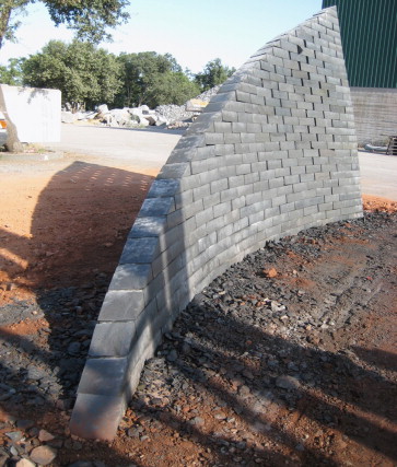
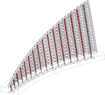
In order to define the feasibility of the new constructive procedure, a full-scale prototype was built. By analogy with the previous study, a portion of a spiral, a “sail” in blocks of Etna basalt was considered. This prototype, consisting of a panel with a thickness of 20 cm, described by an inverted truncated conical surface, has a curvilinear with axis sloped from the vertical by 10°, height ranging from 0 to a maximum of 3.5 m and length of the base to 7.3 m. The sail, without constraints in space throughout its height, at the base is fixed to a foundation of reinforced concrete with a size of 6.6×1, 63×0, 30 m (Figure 1 ; Figure 2 ).
|
|
|
Figure 1. Views of the stone sail. |
|
|
|
Figure 2. Axonometric view of the sail with revealed the system of reinforcements. |
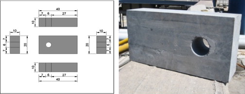
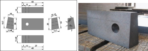
Considering the geometry of the sail and the need to obtain a serial production of the blocks, we used a single block type, rectangular in shape that can assume, by a broken line, the curved shape of the wool artifact.
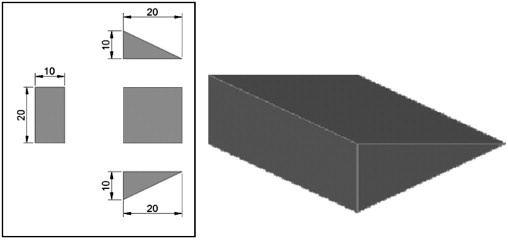
All the blocks are identical except for the basic block, which has a trapezoidal shape, in order to give to the sail the required sloping of 10° and of the head block, which has a triangular shape to give at the top of the sail a continuous shape, non-serrated.
In blocks, achieved by water jet cutting with a diamond disc, a cylindrical hole, with a diameter of 6 cm has been made, using a corer, in order to make room for the reinforcements. The size of the blocks and the hole was studied in order to guarantee the staggered joints and alignment of the hole where the prestressed cable is placed through all the layers (Figure 3 , Figure 4 ; Figure 5 ).
|
|
|
Figure 3. Block type. |
|
|
|
Figure 4. Upper block. |
|
|
|
Figure 5. Bottom block. |
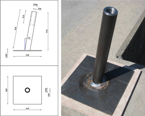
The link system between the sail and the foundation is made up of several elements: one plate, galvanized steel (250 mm×250 mm×5 mm), and a hollow cylindrical element, also made of galvanized steel, consisting of a tubular (F45×M30 l =350 mm), threaded inside ( Figure 6 ; Figure 7 ).
|
|
|
Figure 6. Bottom plate and tubular threaded inside. |
|
|
|
Figure 7. Sleeve. |
The plate is completely embedded within the foundation and the tubular comes out from the top of the foundation (5 cm), so as to allow the tightening between the foundation and steel threaded rods.
The various components have been specifically designed, along with the basic block of trapezoidal shape, to make the joint between sail and foundation work well, where three materials with different mechanical characteristics work: steel, natural stone and concrete.
The threaded rods (diameter 3 cm, length 300 cm), in galvanized steel, inside the hole, are placed from each other at a distance of 40 cm, which corresponds to the size of the block.
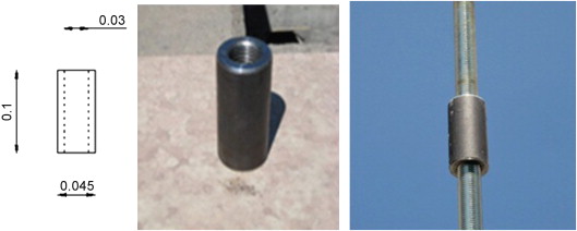
Where the sail has a height greater than 3 m, the rods were linked by a sleeve (F45×M30 l =100 mm) similar to the tubular used in the foundation, providing the absolute transmission of the stress as if it was a seamless single bar.
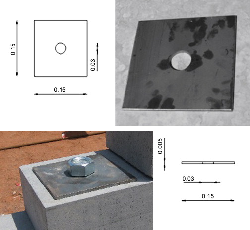
The top closure system, at the last layer of blocks, is made up of a plate, also made of galvanized steel (150 mm×150 mm×5 mm). The rod is linked to the block of head through the top plate and a steel nut (M30-quality 8.8). Each nut has been applied a specific value of tightening to give the required prestressing obtained from structural tests made according to the height of the sail at that point (Figure 8 ).
|
|
|
Figure 8. Upper plate. |
3. Assembly procedure
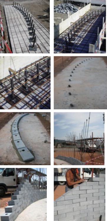
In the foundation, once the steel reinforcement was prepared, the bottom plates were put in place with the threaded cylinder (located at a distance of 0.40 m from each other according to a circular arc of radius 8.65 m) and welded to the bottom reinforcement. The concrete casting to a height of 30 cm was performed making sure to protect the top of the threaded cylinder. Once foundations ended, the first layer of blocks was placed by putting a layer of leveling to improve the adherence between the foundation and the same blocks. They were then clamped for each cylinder threaded rods, having been, in some cases shortened and in others, where the sail was over 3 ft of height, stretched through the use of sleeves (Figure 9 ).
|
|
|
Figure 9. Section and view of the stone sail. |
Having prepared all the steel bars into their housing, we proceeded with the laying of each block. Up to a height of 1.8 m, the building of the sail which took place by sliding the block along the steel rod was done fairly quickly and easily by a single worker, being the weight of the block (23 kg) below that ergonomically permitted by the regulation for a worker. In the part of the sail that exceeded the height of 1.8 m it was necessary to build a small scaffolding and have the support of a second worker who would help to slide the block along smoothly to the height of the steel rods up to the maximum of 3.5 m.
This problem could be resolved, making the assembly easier, using rods with a maximum length of about 1.8 m, linked by sleeves. In this case, the building could be divided into stages, with shooting every time you reached 1.80 m. On the upper face of the last layer of blocks the plates have been positioned and clamped to the rods by tightening the nuts.
For this task we have used a torque wrench which allowed us to give the required prestressing for each rod. The last step was the laying of the head block that gave formal continuity to the sail end, hiding steel plate and nut (Figure 10 ; Figure 11 ).
|
|
|
Figure 10. Steps of sail building. |
|
|
|
Figure 11. View of the stone sail. |
4. Structural testing
The mortar in the prestressed masonry previously studied, placed at the joints between the blocks and in the cylindrical hole that makes room for the reinforcements, gives place to a continuity between the blocks and steel rods; continuity that justifies the assumption of homogeneity on which the finite element method adopted previously is based. For prestressed masonry panels, in dry-assembled stone blocks, the finite element method adopted in the case of panels with mortar, is no longer responsive to the actual state.
The new panels in dry-assembled blocks responds more to a calculus method which takes into account a set of discrete elements (blocks) each of which is subject to the actions provided by the adjacent elements, in absence of intrinsic ties and constraints between one element and others. This involves that while in the proceedings with mortar, the prestressing, provided by steel rods, is distributed uniformly along the entire panel, in the case of dry assembly the prestressing is provided through two concentrated forces acting on determined points at the ends of the panel; forces that are transmitting through the contact faces between a block and each other. The prestressing system used for the stone sail is by sliding cables.
The procedures for calculating the prestressing required to ensure the stability of the sail were made initially on a portion of unit length corresponding to the part of greater height and therefore most stressed of the sail.
According to the weight of the structure and stresses due to the wind, which in this case are higher than those of the earthquake, the steel rods have a prestressing that was elaborated by imposing that the center of stress is always found within the central core of inertia of the block so as to have the whole section of the sail always compressed.
On the panel act, in the horizontal direction: the component of the prestressing load, the wind load and the friction force between the blocks, in vertical direction: the weight load and the component of prestressing load. Taking into account the geometric data of the structure, in the highest point of sail, a prestressing load of 10,000 kg was calculated. We, then, proceeded to test that the maximum stress acting on the individual blocks is always lower than stone resistance.
In particular with this pre-compression the stress acting on the individual block is equal to 76.2 MPa, well below the strength of the basalt which is higher than 100 MPa. Since the sail has a variable height, the calculus procedure was repeated to obtain the value of the prestressing to be applied at the different heights of the structure.
5. Potentials and applications
Technological innovation applied to the load bearing masonry with this research could, through the use of a single material with functional response differentiated, meet the increase of demand quality, linked to traditional materials like natural stone, which still shows to have excellent performance characteristics.
Within a sustainable building design, both in the case of new projects in the case of recovery of existing buildings, the masonry of prestressed stone blocks can take on different roles. In the recovery of historic buildings, it is interesting to note that using a material similar or equal to that already present, the stiffness is not altered.
When used in building envelopes, over the water resistance, which should be ensured by a precision cut made by numerical control machines on the individual blocks, the prestressed masonry has a good performance in relation to the thermal behavior. Indeed, this masonry, thank to high thermal inertia even in the presence of small thickness, coupled to the thermal insulation, provides excellent thermodynamic performance in areas with a Mediterranean climate characterized by high thermal shock (Lombardo and Cicero, 2011a ; Lombardo and Cicero, 2011b ).
The sail designed in Etna basalt presents results that can be applied to many other natural stones from other regions, thus promoting the use of a material that is not only natural but also local, in alternative to the idea of a good material at international level that in recent years has led to a process of homogenization of the image of the city.
6. Conclusion
The design of the new constructive procedure arises from the consideration that, due to the high compressive strength of the stone, you can artificially stress the masonry in order to improve performance. The expectations that have led to the definition of constructive procedure in load-bearing masonry, in dry-assembled and pre-compressed blocks of natural stone through reinforcing steel, have been confirmed by results that led to the construction of a full-scale prototype. This prototype consists of a curved wall panel, sloped by 10°, with a thickness of 20 cm and height at the highest point of 3.5 m. The panel, fixed at the base and free on the other sides, because of the shape and thinness, it is of considerable visual impact, as its appearance reminds us of the sail of a boat stretched by the wind. Although it loaded to flexure and fixed only to the end, it shows conditions of perfect balance.
The experiment, which has seen the effective construction of the sail, shows that the state of artificially induced stress to reinforcements located within the blocks led the masonry panel to resist stresses such as flexure and traction, otherwise unthinkable. So you could say that the prestressing really profoundly altered the mechanical behavior of masonry giving this typical behavior of elastic materials, such as structural steel and reinforced concrete.
From a morphological point of view this is a fact that allows you to rethink the load-bearing masonry structures in a completely different key than in the past, by encouraging more articulate shapes in space, with lower constraint conditions that until now have limited certain freedom in the design. The prestress made to the wall, also exceeds, in some way, the principle on which you set the current regulations for reinforced masonry in seismic areas. In fact this assumes conditions of constraints that lead to a structural function of box-type.
This is ensured, for example, by the connection between panels and floor through the beams, the link between the bearing walls made through the setting up of appropriate reinforcements at the joints, the management of full and empty in the outer walls to ensure structural continuity of the bearing elements and much more.
Besides the outstanding morphologic and aesthetic potentialities which allow for the development in architecture projects, it is interesting to note the significant reduction of the thickness of the wall, in reference to those specified in the regulations. This allows you to build very slim panels as in the case of the wing that has a thickness of 20 cm and a height of 3.5 m. The remarkable reduction of the thickness of structural elements made of prestressed masonry has as a direct result a considerable saving of building material. Reducing the material used is definitely in favor of the sustainability of the procedure, although, in fact, the natural stone, compared with other very widespread construction materials, has a sustainable behavior.
Sustainability as well as being designed for the raw material also affects procedure. In fact, the structure built with dry-assembly process, responds well to the typical requirements of sustainable construction in the reversibility and recycling of components. Also construction flexibility can lead to a broad diversification in the use of the system and to satisfy a wider range of needs in the building.
The fact that the production and working of Etna stone in the territory of eastern Sicily, are still largely tied to traditional systems, is a big limit to a development of the entire sector. The prototype has therefore had to reconcile an industrialized construction process by the use of numerical control machines with a working stone system still tied to the principles and techniques of handicraft type. This has meant, for example, the choice of a single block type to make the whole structure except at the ends of the layers: three block types in total. As a result the sail with a curved horizontal section was approximated to a broken line.
The use of numerically controlled machines could allow for the perfect making of any of the blocks ad hoc to satisfy the configuration of the sail, avoiding other problems such as that of joints, which gradually progressing from the bottom up, became bigger and bigger.
Also cutting, done with these machines, is much more precise, giving to the block a perfectly square shape with regular faces, promoting a better adhesion between these and therefore a more uniform transmission of the prestressing load. In general, the new proven procedure, coupled with control and working systems on individual blocks, of next generation, gives the possibility to create complex shapes and variously articulated configurations in space.
Another aspect taken into consideration during the design is that in the assembly, each element has been designed thinking about its possible assembly and the ease with which this should be done, in such a way to minimize the work of precision of the installation, only required for leveling the foundation and for tightening the steel rods. In fact, the deadlines for completing the whole work have been very short, five days for the foundation, contemplating the timing of maturation of the concrete casting, and one day for the structure in elevation. It should also be underlined that the procedure did not require the use of a specialized workforce.
In the prototype any waterproofing membrane for the protection of reinforcements has not been prepared because this will not undergo durability testing, after making the mechanic tests it will be removed. In continuation with the research, mechanical testing, currently under development, will help validate the results obtained by numerical calculations, highlighting the extent to which the actual behavior of the panel is similar to that assumed in the calculation model.
References
- Cicero and Lombardo, 2011 C. Cicero, G. Lombardo; Buildings envelopes and energy; Journal of Civil Engineering and Architecture (8) (2011) David Publishing
- Hammond and Jones, 2011 G. Hammond, G. Jones; Inventory of Carbon & Energy (ICE). Version 2.0, Department of Mechanical Engineering; University of Bath, UK (2011)
- Lombardo, 2004 G. Lombardo; La modernità del basalto dell'Etna Innovazione e sperimentazione; Il Lunario Enna (2004)
- Lombardo, 2005 G. Lombardo; Innovazione tecnologica nelle opere di Peter Rice, in Atti del convegno internazionale: Teoria e Pratica del costruire: saperi, strumenti, modelli; Esperienze didattiche e di ricerca a confronto, Ravenna (2005)
- Lombardo, 2007 Lombardo, G., 2007. The return of the stone in architectural composition. In Atti del Terzo congresso internazionale Ar.Tec. “L'involucro edilizio. Una progettazione complessa”, Ancona. 21–23 novembre 2007, FIRENZE, Alinea editrice, Italy.
- Lombardo, 2010 Lombardo, G., 2010. Built architecture with natural stone. In Atti del convegno internazionale: 37th IAHS World Congress on Housing “Design, Technology, Refurbishment and Management of Buildings, 26–29 October 2010, Santander, Spain. International Journal for Housing Science and Its Applications 35(2) 2011.
- Lombardo, 2012 G. Lombardo; Weightiness and lightweight for a temporary architecture sustainable; Journal of Civil Engineering and Architecture (1) (2012) David Publishing
- Lombardo and Cicero, 2011a G. Lombardo, C. Cicero; Building envelope and energy; Journal of Civil Engineering and Architecture (11) (2011) David Publishing
- Lombardo and Cicero, 2011b Lombardo, G. Cicero, C. 2011b. Materiali ed energia nella progettazione dell'involucro edilizio, Il Progetto Sostenibile, n. 30.
- Zanelli, 2003 Zanelli, A., 2003. Trasportabile/Trasformabile. Idee e tecniche per architetture in movimento, CLUP, Milano.
Document information
Published on 12/05/17
Submitted on 12/05/17
Licence: Other
Share this document
Keywords
claim authorship
Are you one of the authors of this document?
