Summary
Timber constructions made of round timber components are becoming more and more popular. Given that in the current European standards for the design of timber structures, timber-to-timber joint type is solved only for squared timber. This paper presents results of static tests in tension at an angle of 0°, 90°, 60° to the grain of round timber bolted joints. This research looks into reinforcement with modified washers or self-drilling screws, as these are the least labour-intensive (while economically advantageous). The joints samples were experimentally tested in the laboratory of the Faculty of Civil Engineering VŠB TU Ostrava.
Keywords
Round timber ; Joint ; Reinforcement ; Self-drilling screw ; Washer
Introduction
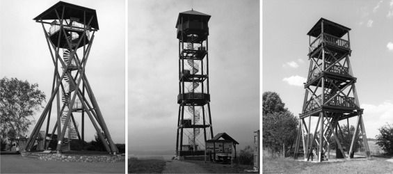
Timber constructions made of round timber components have become vastly popular. Current trends in the field of tourism and leisure industry use eco-structures that are environmentally friendly and made of natural materials. Round timber structures (milled or just stripped of bark) meet these requirements adequately. These are view-towers, bridges for pedestrians, visitor centres in natural parks and a ZOO, or other landscape conceptions. Timber constructions development was, to a certain extent, restricted in the second half of the last century in the Czech Republic. Recently, builders have begun to recourse to timber structures yet again, thus following in a long tradition of using timber as a construction material. In 2011, the highest round timber view-tower in central Europe was opened to the public in village Bohdaneč (Straka and Šmak, 2011 and Fojtík et al., 2015 ).
The tower reaches a height of almost 53 m (Fig. 1 ).
|
|
|
Figure 1. Various types of round timber view-towers. |
If these constructions are created with truss supporting system (e.g. view-towers, pedestrian bridges), elements connections are often designed of steel bolts with embedded steel plate. In the current European standards for the design of timber structures (Eurocode 5, 2006 ), the issue of timber-to-timber joint type is addressed only for squared timber, which makes the pinpointing of the round timber bolted joints carrying capacity near-unfeasible due to the insufficient support in the current standards. One of the key prerequisites of the effective use of timber as a construction material is the guarantee of material technical parameters. Prior to round timber material being used in a construction, its technical properties have to be checked and verified. Mechanical reinforcement possibilities of round timber bolted joints were investigated and tested in the laboratory of the Faculty of Civil Engineering in Ostrava.
Reinforcement design
Timber as a material is characterized by a brittle mechanical behaviour, which means only a relatively small deformation, can be measured before the members fail. Given that this phenomenon is not desirable when designing constructions, a certain high level of deformability of joints is looked for in the design of the connections lest a splitting of the connected parts occur. Elastic–plastic behaviour of joints with sufficient joint ductility is ideal.
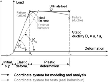
As apparent in Fig. 2 , for some fasteners, an initial slip occurs. If the fastener is loaded, it comes into contact with the hole until it is pressed completely against it (embedded). As the load is increased yet further, a linear (more or less) behaviour between the loading and displacement can be found. Should the joint have scant deformation capacity before it reaches the ultimate load (in other words brittle behaviour), the failure occurs without a prior warning. On the other hand, ductile joints are characterized by significant deformations before they reach the ultimate load, thus a ductile failure mode is more than desirable in well-designed joints (Augustin, 2008 ).
|
|
|
Figure 2. Typical load-slip-curve of joints (Augustin, 2008 ). |
From a technical point of view, the joints have met the following key requirements: load carrying capacity, stiffness and ductility. Load carrying capacity and effectiveness of every joint is demarcated by the connected elements and the way the internal forces in the joint are transferred or rather distributed. In order to increase the load carrying capacity of a joint, and especially its ductility, it is expedient to further reinforce the wooden element in an area of the joint, which will encourage the joints ductile behaviour.
Thus, a means of strengthening is designed as an element working in wood in the proximity of a dowel in a direction perpendicular to the grain, and in doing so causing the strengthening and clamping of the wood, thus increasing the resistance against a crack occurrence as well as splitting. Wood in tension shows low plasticity and gets damaged by a brittle fracture (Smith et al., 2013 ). In the case of unreinforced joints being damaged, the splitting of the wood underneath a dowel would come about very soon and very shortly after the first crack appeared, when, generally, the load carrying capacity in tension perpendicular to the grain is exceeded and the cross ties within the fibres are torn (Blass and Schädle, 2011 ). Not only was the aim of the reinforcement to increase the joint load carrying capacity, but, equally importantly, to increase the safety of the joint by increasing the plastic deformation preceding the ultimate joint destruction. The destruction of the joint does not come about as fast and unexpectedly as it does with unreinforced joints.
Self-drilling screws for wood with double thread 6.5 mm × 90 mm (company SFS Intec) were used for this reinforcement. The screw was placed in a longitudinal direction 40 mm off the dowel axis, and 20 mm of the round timber edge in a cross direction. For the modified washers approach, the washers were made from steel plate with a thickness 6 mm, category S235. The dimensions of these plates were 60–100 mm. Holes with a diameter of 22 mm were used. The washers were rounded to fit tightly to the round timber sample, and the wood in the bolt area was clamped tightly as well.
Materials and methods
As spruce is the most common type of timber, spruce timber was used as samples for testing. A few non-destructive tests were carried out before the onset of the static tests in the press (Lokaj and Klajmonová, 2013 ). The test samples were weighed on a laboratory scale, along with their moisture and dimensions being measured. The thickness of the annual rings and the slope of grain were also measured. The measured values allowed the density to be assessed. Before the samples were used, timber was deposited in a drying chamber for the moisture stabilization. The average moisture was 12.4%. The average value of apparent density reached 430 kg/m3 . The average thickness of annual rings was 3.21 mm.
Dimensions of the test samples were adjusted to the equipment possibilities of the laboratory at the Faculty of Civil Engineering. Thus, member length was 450 mm (for tests in tension at an angle of 0°) and 560 mm (for tests in tension at an angle of 60° and 90°) and diameter was 120 mm. The bolts made of high strength steel (category 8.8) were used. The connection plates were made of steel S235 with thickness of 8 mm, length of 290 mm and width 80 mm. Holes in steel plates and timber with diameter 22 mm respectively 20 mm were used. The distance of the holes to the free end in timber was 140 mm, in steel 50 mm.
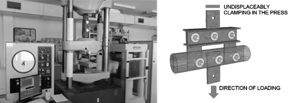
A steel product for the load distribution testing was manufactured (Fig. 3 ). In order for the load direction to be perpendicular to the grain, the samples were subjected to a simple tensile test with the tension force being increased gradually. The test parameters were invariable for all the samples. See Klajmonová and Lokaj (2014) and Lokaj and Klajmonová (2014) for more information about the tests. Tests of strength in tension under different angles to the grain in order to gain the general knowledge about the behaviour of reinforced joints using self-drilling screws were carried out. Sets of static tests in tension parallel to the grain were conducted as well as under an angle of 90° and 60° to the grain.
|
|
|
Figure 3. (left) Test sample in press machine; (right) steel product for load distribution testing. |
Experimental testing
Each round timber sample which was subjected to a simple tension test had the same test parameters. The tension force on samples loaded parallel to the grain was increased gradually. Choosing rate of displacement of the press jaws was optimal. Each specimen failure occurred in time boundary of 300 ± 120 s. It corresponds to the current European standard.
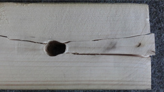
First, the unreinforced samples were tested, which resulted in all of them being damaged by splitting. The samples failure was caused by exceeding the timber strength in tension perpendicular to the grain. Embedment underneath the bolts grew during the loading, and the crack came about. During the next loading, the crack grew rapidly until the ultimate damage. The damaged samples are shown in Fig. 4 .
|
|
|
Figure 4. Damaged unreinforced samples. |
Subsequently, sets of self-drilling screws and modified washers reinforced samples were tested. As expected, there was an increase in the load carrying capacity as well as in the joint ductility. There was a drop in strength after a crack initiation with some of the reinforced samples, however, with the additional load being exerted upon the samples these showed high residual strength and, on the whole, were not damaged until after significantly bigger load was applied – compared to the unreinforced ones. Some samples were damaged by plug shear (Fig. 5 ).
|
|
|
Figure 5. Plug shear failure of reinforced sample. |
Results and discussion
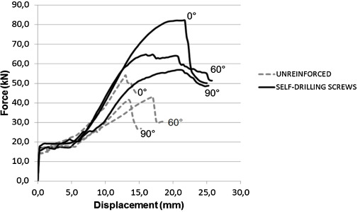
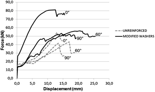
Test results of reinforced and reinforced samples subjected to tension at different angles to the grain are shown in Table 1 . The comparison of both unreinforced and reinforced samples behaviour is graphically displayed in Figure 6 and Figure 7 . The following graphs show that the reinforcement of joints leads not only to a significant increase in load capacity of joints in tension, but, above all, considerable increase in plastic deformation of a joint, which results in a subsequent increase in the joints reliability and safety. This means the joint becomes less brittle and prone to an instant collapse, albeit at the cost of increased deformation. The joints reinforcement also leads to an increase in the joint stiffness.
| Samples type | Value | Tension orientation at an angle to the grain | ||||||||
|---|---|---|---|---|---|---|---|---|---|---|
| 0° | 60° | 90° | ||||||||
| SD | CV | SD | CV | SD | CV | |||||
| Unreinforced | Wood density (kg/m3 ) | 447.2 | 43.4 | 9.7 | 405.9 | 26.4 | 6.5 | 414.9 | 46.2 | 11.1 |
| Joint capacity (kN) | 62.6 | 6.3 | 10.4 | 41.7 | 4.8 | 11.6 | 40.6 | 5.0 | 12.5 | |
| EC 5 (kN) | 57.5 | 30.8 | 28.5 | |||||||
| Modified washers | Wood density (kg/m3 ) | 453.9 | 52.3 | 11.5 | 463.6 | 55.9 | 12.0 | 429.6 | 40.8 | 9.5 |
| Joint capacity (kN) | 81.9 | 13.1 | 16.1 | 59.6 | 5.3 | 8.9 | 54.4 | 6.5 | 12.1 | |
| Self-drilling screws | Wood density (kg/m3 ) | 397.3 | 61.7 | 15.5 | 443.2 | 35.7 | 8.0 | 422.5 | 31.3 | 7.4 |
| Joint capacity (kN) | 81.1 | 13.7 | 16.9 | 62.4 | 8.5 | 13.7 | 54.0 | 4.7 | 8.8 | |
|
|
|
Figure 6. Comparison of test records of unreinforced and samples reinforced with self-drilling screws. |
|
|
|
Figure 7. Comparison of test records of unreinforced and samples reinforced with modified washers. |
Conclusions
Allowing for the number of the samples being small, the presented results are bound to bear statistical errors. The response of all the tested joint samples without reinforcement showed certain common signs. After the initial joint deformation (meaning a displacement of approximately 5 mm), which was brought about by a different diameter of the dowel and the hole in the steel plate, an almost linear phase of the joint work diagram up to the level of 80% of the maximum load carrying capacity occurred. After having exceeded this load level, an audible cracking and a plastic deformation of the joint came about, meaning the deformation of the joint grew more than would normally correspond to its force development. As the result there was a rapid splitting of the wooden element in its final phase in the area between the dowel and the edge of the round timber.
The reinforced samples were able to absorb around 20% more pressure before cracking than the unreinforced ones. The reinforcement of the wooden element in the area of the dowel caused not only an increase in strength, but also an increase in the joint ductility. The reinforced joints did not break in a brittle way. The collapse came about gradually and accompanied by large deformations. These reinforcing methods are inexpensive owing to the usage of affordable parts. In terms of fire resistance, advantage of the reinforcement using self-drilling screws is little disruption of the wooden element. The surface of the screw head, which is exposed to fire, is small and significantly reduces the amount of heat that can pervade the wood. Countersunk-head bolt can also act as a screw, where the head of the screw is covered up by a cap of some sort (Klajmonová and Lokaj, 2015 ). Further or follow-up work, which is being considered in this area, is to gather more samples for testing and thus eliminating the statistical error.
Conflict of interest
The authors declare that there is no conflict of interest.
Acknowledgements
This outcome has been achieved with funds of Conceptual development of science, research and innovation assigned to VŠB – Technical University of Ostrava by Ministry of Education Youth and Sports of the Czech Republic in 2015 under identification number IP2215541.
References
- Augustin, 2008 M. Augustin; Ultimate limits states-joints; Education Materials for Designing and Testing of Timber Structures – TEMTIS, Handbook 1 – Timber Structures (2008)
- Blass and Schädle, 2011 H.J. Blass, P. Schädle; Ductility aspects of reinforced and non-reinforced joints; Eng. Struct., 33 (2011), pp. 3018–3026
- Eurocode 5, 2006 Eurocode 5; Design of Timber Structures – Part 1-1: General – Common Rules and Rules for Buildings; (2006)
- Fojtík et al., 2015 R. Fojtík, A. Lokaj, D. Mareček; Diagnostics of footbridge over the Jizera river in Benešov; Appl. Mech. Mater., 752–753 (2015) ISSN 1660-9336
- Klajmonová and Lokaj, 2014 K. Klajmonová, A. Lokaj; Round timber bolted joints with mechanical reinforcement; Adv. Mater. Res., 838–841 (2014), pp. 629–633 http://dx.doi.org/10.4028/www.scientific.net/AMR.838-841.629
- Klajmonová and Lokaj, 2015 K. Klajmonová, A. Lokaj; Round timber bolted joints reinforced with self-drilling screws; Proc. Eng., 114 (2015), pp. 263–270 http://dx.doi.org/10.1016/j.proeng.2015.08.067
- Lokaj and Klajmonová, 2013 A. Lokaj, K. Klajmonová; Carrying capacity of round timber bolted joints with steel plates under static loading; Trans. VŠB Tech. Univ. Ostrav. Civ. Eng. Ser., XII (2) (2013), pp. 100–105 2013
- Lokaj and Klajmonová, 2014 A. Lokaj, K. Klajmonová; Round timber bolted joints exposed to static and dynamic loading; Wood Res., 59 (3) (2014), pp. 439–448
- Smith et al., 2013 I. Smith, et al.; Fracture and Fatigue in Wood; John Wiley & Sons, England (2013)
- Straka and Šmak, 2011 B. Straka, M. Šmak; Joints with steel elements in timber structures (in Czech); Proceedings of International Conference Timber Buildings 2011, Volyně (2011), pp. 151–158
Document information
Published on 05/10/16
Licence: Other
Share this document
Keywords
claim authorship
Are you one of the authors of this document?
