Abstract
The Pulsating Heat Pipe (PHP), lauded for its efficacy in heat transfer, is distinguished by its uncomplicated architecture, economical production, diminutive form, and robust adaptability to environmental conditions. This study delineates the design of an asymmetric PHP heat transfer apparatus, achieved through the alteration of select conduit lengths within the comprehensive circulation system. The thermal transfer efficacy of this apparatus was empirically scrutinized under dual dissipation modalities: natural and forced convection. It was observed that the asymmetric PHP, when devoid of oscillatory activity, maintained a heat source temperature of 25∘C, whereas the temperature escalated to 26∘C upon the initiation of pipe vibration. Under the regime of forced convection, the asymmetric PHP demonstrated expedited activation, reduced initiation temperature, and heightened oscillatory behavior compared to its natural convection counterpart, thereby facilitating the phase change condensation within the condensation segment and ensuring efficient, sustained heat dissipation. Consequently, this bolstered the PHP’s heat transfer capabilities. The thermal resistance exhibited a declining trajectory under both dissipation strategies, with forced convection consistently yielding lower thermal resistance than natural convection. Nonetheless, the decrement in thermal resistance was gradual near the critical startup juncture and throughout the initiation phase. The PHP’s equivalent thermal conductivity displayed an upward trend in tandem with the escalation of the heat source’s temperature under both dissipation methods. Despite the superior heat transfer performance at elevated heat source temperatures, the efficiency of natural convection dissipation remained suboptimal, necessitating the application of forced convection to the condensation segment to further enhance the PHP’s thermal transfer proficiency and the overall device performance.
Keywords: PHP, natural convection, forced convection, efficient heat transfer
1. Introduction
In the contemporary era marked by the relentless advancement of science and technology, the escalation of energy consumption necessitates the pursuit of sustainable energy development as a paramount research domain. Originating in the 1960s, heat pipe technology—predicated on the rapid heat transfer facilitated by heat conduction and phase change mediums—employs an internal wicking structure to effectuate heat exchange, exhibiting commendable thermal transfer capabilities.
The Pulsating Heat Pipe (PHP), an emergent high-efficiency thermal transfer component, capitalizes on the inherent thermal conductivity of copper, alongside the sensible and latent heat of the working fluid, to effectuate heat transfer. Its ascension to prominence is attributed to its rudimentary architecture, cost-effectiveness, absence of acoustic emission, capability for arbitrary bending, proficiency in long-range heat transfer, and versatile configuration [1]. PHP’s potential is currently being harnessed in a multitude of applications, including the cooling of electronic apparatus [2,3], recuperation of waste heat [4,5], heating, ventilation, and air conditioning systems (HVAC), cryogenic technology [6-9], nuclear energy, novel heat transfer methodologies in renewable energy, solar thermal exploitation [10,11], thermal management of automotive batteries [12], and high-temperature superconductivity [13].
Despite its simplistic structure, the intricate interplay of hydrodynamic and thermodynamic phenomena within PHPs engenders a complex internal operational mechanism. The thermal performance of PHPs is contingent upon a plethora of experimental parameters, such as the quantity of turns, fill ratio, tube diameter, working fluid’s physical properties, contact angle, and inclination angle, rendering a comprehensive elucidation of PHP’s flow dynamics from a singular investigative approach challenging [14,15]. Extensive research has been conducted on these determinants; for instance, Rudresha et al. [16], Jang et al. [17] and Wu et al. [18] have demonstrated that optimal thermal transfer in PHPs is achieved with a working fluid fill ratio ranging from 50% to 70%. The tilt angle’s impact on PHPs predominantly manifests through gravitational effects [19-21], with optimal performance observed when heating is applied at the base in a vertical orientation. Moreover, academic endeavors have been directed towards enhancing fluid circulation by modifying the PHP structure, thereby optimizing thermal behavior [22-24]. In essence, the PHP is influenced by an array of factors, and the internal two-phase flow and heat transfer processes are intricate, necessitating further in-depth exploration of the heat transfer mechanisms.
Current research on the asymmetric design of PHPs is sparse; thus, this study innovates by altering the lengths of specific segments within the PHP structure, engendering an asymmetric, staggered configuration. This paper introduces a novel asymmetric PHP heat transfer apparatus, leveraging the asymmetry and resultant potential difference to induce differential flow resistance and driving forces across various regions within the asymmetric pipeline. This local pressure differential serves as a catalyst for the working fluid to migrate towards areas of lower resistance. A comprehensive comparative analysis of the device’s thermal performance is undertaken, encompassing startup and operational phases, across diverse heat source temperatures, and under both natural and forced convection conditions.
2. Experimental setup
2.1 Experimental facility
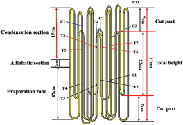
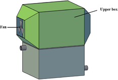
Depicted in Figure 1(a), the pulsating heat pipe (PHP) heat exchanger under scrutiny is comprised of 24 unaltered straight copper tubes and an equal number of copper elbows. The tubes boast an inner diameter of 3mm and an outer diameter of 5mm, with distilled water serving as the internal medium. The apparatus’s stature stands at 370mm, with the evaporative and condensing segments maintaining a consistent length of 170mm each, while the adiabatic section extends 30mm. A deliberate truncation of 70mm from portions of the evaporative and condensing sections’ piping contributes to the asymmetric internal architecture. As illustrated in Figures 1(b) and (c), the evaporative section is immersed in the lower case’s hot water, segregated from the condensing section by a central partition, ensuring no interference between the upper and lower segments. The condensing section employs both natural and forced convection methodologies for heat dissipation.
| ||||||||
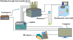
| Figure 1. (a) Internal structure diagram. (b) Natural convection device. (c) Forced convection device.(d) Experimental system diagram |
2.2 Experimental system and experimental method
Figure 1(d) delineates the experimental setup for assessing the thermal performance of an asymmetric pulsating heat pipe (PHP) heat exchanger. The system encompasses the PHP heat exchanger with its asymmetric design, a data acquisition unit, a precision-controlled thermostatic water bath, computational resources, flow regulation mechanisms, a hotline anemometer, and an infrared thermal imaging camera. The experiment utilizes a thermostatic water bath to furnish a spectrum of heat source temperatures, maintaining a precision of ±0.05℃, while the flow of hot water is meticulously modulated by flow controllers. The cooling mechanism bifurcates into natural air convection and fan-induced forced convection modalities. Temperature measurements in the natural convection condensation segment are executed using a VarioCAM HD infrared camera, capturing data at 1-second intervals with an accuracy of ±0.05℃. Conversely, the forced convection segment employs a nickel-chromium-nickel-silicon (K-type) armored thermocouple, interfaced with an Agilent 34980A data collector for real-time temperature monitoring, adhering to the same temporal frequency and precision. Concurrently, the wind velocity within the upper compartment is ascertained through a hot-wire anemometer.
The subject of the experiment is the asymmetric PHP heat exchanger, charged with a 50% distilled water fill rate as the working fluid. Multiple temperature sensing points are strategically positioned along the evaporation and condensation sections, with additional singular points at the water ingress and egress. The thermostatic water bath is calibrated to generate five distinct heat source temperatures: 25℃, 26℃, 40℃, 60℃, and 80℃. During natural convection operations within the condensation section, ambient air temperature is meticulously maintained at 21℃. For scenarios involving fan-forced convection, temperature is gauged at singular points at both the air inlet and outlet, with the anemometer recording a wind speed of 0.7m/s.
2.3 Data handling
This paper focuses on the characteristics of PHP such as startup, operation, and heat transfer performance. For the heat transfer performance, the heat transfer thermal resistance, the temperature difference between the heating section and the condensing section, and the equivalent thermal conductivity are used as the measurement indexes, and the calculation equations are as follows:
|
|
(1) |
|
|
(2) |
|
|
(3) |
|
|
(4) |
where, and are the average temperature of the evaporation section and the condensing section, , respectively; is the pulsating heat pipe evaporation section of the heat absorbed, ; is the heat transfer thermal resistance, K/W; is the equivalent coefficient of thermal conductivity, W/(m·K); is the total cross-sectional area of the pulsating heat pipe circulation pipeline, m2; is the pulsating heat pipe evaporation section and the condensing section of the average distance between the measurement point, .
3 Results and Analysis
3.1 Start-up and running characteristics analysis
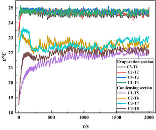
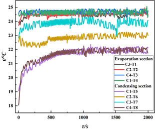
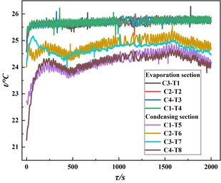
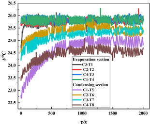
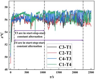
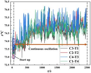
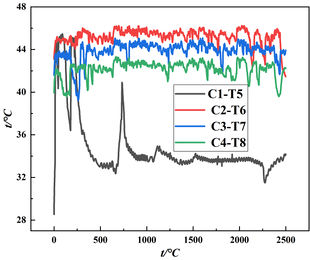
As elucidated in Figure 2, the heat source temperature set at 25°C, whether employing natural or forced convection for heat dissipation, fails to induce oscillatory behavior at the evaporative terminus or within the condensing section of the pulsating heat pipe (PHP). This absence of activity is attributed to the insufficient thermal energy available at the evaporative section to initiate the phase transition and subsequent flow of the working fluid. Conversely, at a slightly elevated temperature of 26°C, a nascent oscillation is observed under both dissipation scenarios, establishing this temperature as the threshold for PHP activation. This subtle oscillatory behavior arises from localized heating, where the working fluid absorbs thermal energy, vaporizes into diminutive bubbles, and transports the absorbed heat from the evaporative end to the condensing section. Upon reaching the condenser, these bubbles collapse, releasing their thermal content. However, the low thermal flux density at this juncture means that the heat conveyed to the PHP’s evaporative end is minimal, resulting in a marginal generation of vapor and a negligible pressure differential within the tube. Consequently, the PHP does not fully activate, and the working fluid within struggles to vaporize into a substantial volume of bubbles, precluding any vigorous or sustained oscillation. Thus, Figure 1 demonstrates that while the minimum operational temperature for the device is 26°C, marked by feeble oscillations, at 25°C, the PHP exhibits no such activity, confirming that at 26°C, the PHP remains functional for heat transfer purposes.
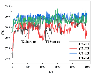
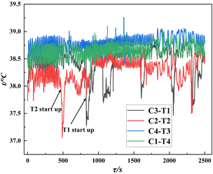
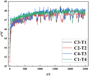
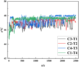
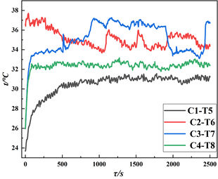
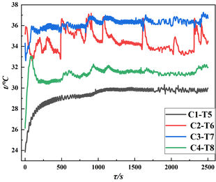
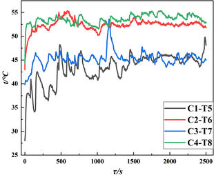
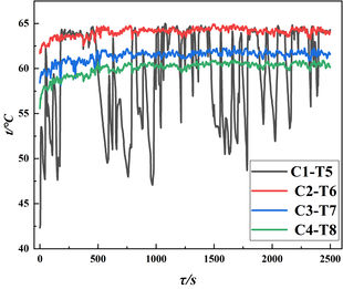
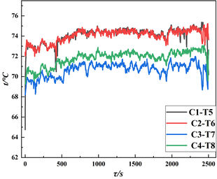
Insights gleaned from Figures 3 and 4 reveal that, at a heat source temperature of 40°C and under the influence of natural convection, the evaporative segments of channels C2 and C3 within the pulsating heat pipe (PHP) apparatus exhibited a discernible temperature jump indicative of activation. In contrast, channels C1 and C4 remained dormant, lacking any such thermal upsurge, attributable to the heat source’s insufficiency in catalyzing the working fluid’s phase transition within these channels. Despite this, oscillatory behaviors of varying magnitudes were observed across all channels’ evaporative and condensing sections. Notably, initiation points T1 and T2 were recorded at 1108s and 532s, corresponding to activation temperatures of 38.64°C and 39.20°C, respectively. Channel C2 demonstrated a more rapid and lower-temperature onset compared to C3, and although both channels ceased operation post-activation, the post-initiation oscillations in C2 were characterized by greater amplitude, frequency, and duration. This phenomenon is ascribed to the elevated heat source temperature, which engenders an accumulation of thermal energy in the evaporative section, thereby increasing the proportion of gaseous plugs within the capillary circuit. Consequently, the pressure differential between the evaporative and condensing sections escalates, propelling the working fluid towards the condenser. The shorter length of channel C2, coupled with its higher heat flux density and reduced heat transfer distance, facilitates the overcoming of gravitational forces, enabling the working fluid to ascend from the evaporative base to the condenser. Despite a lower heat source temperature, the diminished gravitational force requisite for mass transport from the evaporative lower section to the condenser lessens, and the pressure imbalance between the extremities and adjacent tubes progressively intensifies. This culminates in the amplification of the working fluid’s oscillatory motion and an acceleration of its flow rate. In contrast, the extended length of channel C3’s condensing section augments the frictional resistance and gravitational forces encountered during mass flow, necessitating a more substantial pressure differential to sustain mass movement, thereby causing transient flow followed by stasis within the channel, while the flow in channel C2 persists for a more extended duration.
| ||||||||||||||||||||||
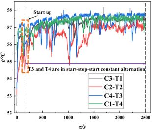
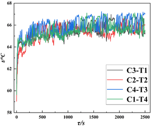
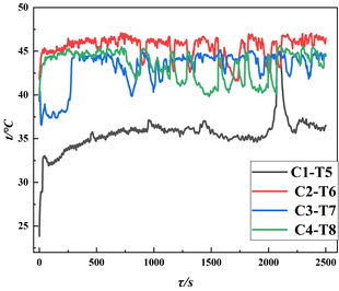
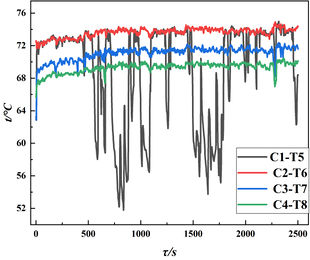
| Figure 3. Temperature fluctuation curves of PHP evaporation section of the device under natural convection and forced convection at heat source temperatures of 40°C, 60°C and 80°C | ||||||||||||||||||||||
| ||||||||||||||||||||||
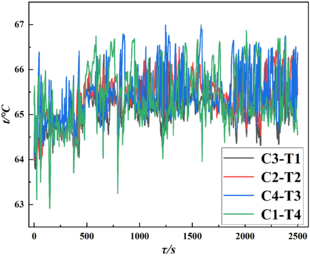
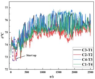
| Figure 4. Temperature fluctuation curves of PHP condensing section of the device under natural convection and forced convection at different heat source temperatures | ||||||||||||||||||||||
In an experimental setup with a heat source maintained at 40℃, employing forced convection for heat dissipation, the temperature at measuring points T1 and T2 was recorded at 826s and 461s, respectively. Initial temperatures were observed to be 38.52℃ at T1 and 38.15℃ at T2. These conditions, when compared to natural convection scenarios, indicated a more rapid initiation and a lower commencement temperature, suggesting that the pulsating heat pipe (PHP) is predisposed to a more efficient start. Notably, in the C2 and C3 channels, both the evaporation and condensation sections exhibited a distinctive start-stop-start pattern on the temperature curves at T1, T2, T6, and T7, with the C2 channel demonstrating a particularly pronounced oscillation amplitude. This phenomenon is attributed to the equal lengths of the evaporation sections in both channels, which correspond to the height of the measuring points. However, the temperature at T1 consistently exceeded that at T2. This discrepancy is explained by the lower flow resistance in the C2 channel, which facilitates an easier initiation of flow. The intermittent flow within the channel, coupled with a differential pressure driving force, directs the mass flow towards the path of least resistance. Consequently, a portion of the mass in the C3 channel’s evaporation section is diverted to its condensation section, while another fraction is channeled to the adjacent C2 channel, enhancing the mass flow therein. This interaction results in more pronounced oscillations within the C2 channel and, due to heat dissipation during the flow process, a measurable heat loss occurs as the mass transitions from the C3 to the C2 channel, culminating in a lower temperature at T2 compared to T1.
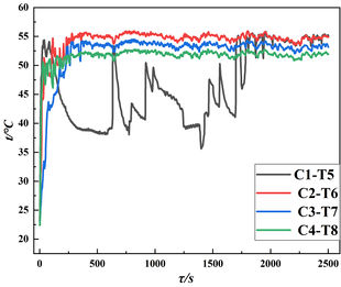
Upon elevating the heat source to 50℃, an increase in both the oscillation amplitude and frequency across all channels was observed, concomitantly with a reduction in the initiation time under both modes of heat dissipation. All channels, with the exception of C1—which ceases operation post-initiation—demonstrated a start-stop-start intermittent oscillation pattern, more pronounced under forced convection heat dissipation. At a heat source temperature of 60°C, the channels of the pulsating heat pipe (PHP) commenced operations simultaneously under both heat dissipation methods. The forced convection mode notably reduced the overall startup duration of PHP compared to natural convection, as depicted in Figure 3, with the C4 channel’s initiation velocity trailing only behind that of the C2 channel. This is attributed to the C4 channel’s evaporation section being lengthier than its condensation section, amassing a greater quantity of phase-change-induced bubbles, thereby propelling an augmented thermal fluid flow towards the condensation section and facilitating the internal circulation of the working mass within the heat pipe. Under natural convection, the C2 and C3 channels persisted in a start-stop-start intermittent flow state post-initiation; however, with prolonged heating, the temperature curves of the evaporation and condensation sections transitioned to a state of sustained oscillation. Conversely, the C1 and C4 channels maintained an intermittent flow state throughout the temperature measurement duration. In the realm of forced convection, following the initiation of the C2 and C3 channels, the evaporation and condensation sections underwent a brief period of intermittent oscillation before stabilizing into a continuous oscillation state. The C4 channel experienced intermittent flow until 1071s post-initiation in the evaporation section, thereafter persisting in oscillation, while the condensation section exhibited stable and continuous oscillation from the onset. The temperature measurement curves for the evaporation and condensation sections of the C2, C3, and C4 channels revealed a gradual convergence in oscillation patterns, indicating a shift in the working mass flow within the various channels from a multidirectional to a unidirectional state. The C1 channel’s evaporation and condensation section temperature measurement points oscillated continuously from initiation until 2242s, necessitated by the extensive heat transfer distance within the C1 pipeline, which required overcoming significant gravitational and frictional forces to transport the working mass from the lower evaporation section to the upper condensation section. The heat source temperature was insufficient to sustain a continuous flow of the working material in a brief timeframe, rendering it challenging to achieve a stable and continuous oscillation prematurely. Nonetheless, as the heating duration extended, the continuous flow in the other channels propelled the working material flow within the C1 channel, eventually leading to a stabilized continuous oscillation in the latter stages.
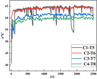
At a heat source temperature of 70℃, the initiation times for all channels were notably brief and uniform across both heat dissipation methods, subsequently stabilizing into a continuous oscillation state. This suggests a transition of the tube mass flow towards a unidirectional circulation. Notably, under forced convection heat dissipation, the channels exhibited an enhanced continuous oscillation effect. When the heat source was increased to 80℃, the initiation times for all channels were the shortest observed, with the pulsating heat pipe (PHP) demonstrating a swifter start. The oscillation amplitude for both the evaporation and condensation sections diminished, yet the frequency reached its zenith. At this juncture, the temperature oscillation trends of all PHP channels indicated that the working mass within the PHP adopted a unidirectional and stable cyclic flow. This is attributed to the elevated heat provided by the heat source to the evaporation section, augmenting the phase change velocity and flow rate of the working mass. A rapid phase transition ensued between the evaporation and condensation sections, characterized by swift bubble formation and growth at the forefront of the liquid plug, culminating in a gas plug compressing a segment of the liquid mass against the wall to form a liquid film. The mass flow transitioned from plug flow to semi-circular and annular flow, rendering the heat transfer within the pulsating heat pipe akin to thin film heat transfer, marked by rapid flow and low-amplitude, high-frequency temperature oscillations at both ends. In the context of forced convection, the performance surpassed that of natural convection in all respects, with forced convection bolstering the condensation of the working mass in the condensation section and enhancing the convection heat transfer coefficient, thereby amplifying the heat transfer rate and quantity. Among the four channels, the C1 channel’s condensation section exhibited the largest oscillation amplitude but a lower frequency, owing to the channel’s symmetrical design and expansive heat transfer area, which facilitated substantial heat transfer from the evaporation to the condensation section, resulting in more vigorous oscillations. However, the extended heat transfer distance in the C1 channel led to a comparatively slower flow rate of the working mass than in the other channels.
Analyses of Figures 3 and 4 reveal that with an increase in the heat source temperature, the asymmetrically structured pulsating heat pipe (PHP) undergoes corresponding changes in the amplitude and frequency of temperature fluctuations within the evaporation and condensation sections. These sections experience oscillatory phenomena characterized by sequences of low-amplitude, low-frequency, followed by high-amplitude, low-frequency, and culminating in low-amplitude, high-frequency oscillations. It is posited that the work within the tube is propelled by a pressure differential induced by heat input, thereby establishing a direct correlation between the oscillation characteristics of the work and the heat input. The flow rate of the working mass dictates the frequency of temperature fluctuations, while the intensity of the working mass oscillation determines the fluctuation amplitude. The asymmetric channel, noted for its ease of initiation and rapid mass flow rate, concurrently drives the flow in adjacent or even the entire channel network. This synergistic effect accelerates the startup of the PHP’s overall structure, hastening the attainment of a stable cyclic flow oscillatory state. In contrast, the symmetric channel with a longer transfer distance exhibits suboptimal heat transfer performance at lower heat source temperatures. However, at elevated temperatures, the heat transfer efficacy is significantly enhanced, resulting in a markedly improved oscillatory effect.
3.2 Comparison of temperature difference between evaporation and condensation section
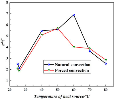
Inspection of Figure 5 elucidates that at a heat source temperature of 25°C and 26°C, the observed temperature differential is minimal. This, however, should not be misconstrued as indicative of optimal heat transfer performance within the pulsating heat pipe (PHP). The phenomenon is attributed to the negligible temperature gradient between the heat source and the ambient environment, coupled with a constrained heat transfer quantity, precluding significant temperature differentials. Under forced convection heat dissipation, the temperature disparity between the evaporation and condensation sections is less pronounced than that observed under natural convection. This method enhances the convective heat transfer coefficient within the PHP’s condensation section, thereby facilitating heat exchange between the PHP’s hot and cold sections and effectively augmenting the convective heat transfer efficacy of the heat exchanger apparatus and the surrounding air.
|
| Figure 5. Average temperature difference between evaporation section and condensation section of PHP monolithic structure under different heat source temperatures |
A slower oscillatory rate engenders a larger temperature differential, whereas an accelerated oscillation reduces it, thereby simplifying the achievement of isothermal heat transfer within the PHP. During the transition from initiation to a pseudo-steady state, despite the sluggish phase change rate of the working mass, forced convection heat dissipation promotes condensation within the condensation section. This accelerates the evaporation and condensation phase change rate across the entire channel, diminishing the temperature differential between the hot and cold sections and enhancing heat transfer performance. With an escalation in heat source temperature, the temperature differential between the PHP’s evaporation and condensation sections uniformly decreases, irrespective of the heat dissipation method employed. As the heat source temperature intensifies, all PHP channels exhibit stable and continuous oscillation. Although the temperature differential between the PHP’s evaporation and condensation sections generally contracts, the disparity under forced convection cooling is marginally greater than that under natural convection. This is ascribed to the increased convective heat transfer coefficient within the PHP’s condensation section under forced convection, which activates the condensation phenomenon within the working mass, leading to temperature oscillations. Consequently, the temperature differential between the PHP’s hot and cold sections is more substantial, resulting in a slightly larger temperature differential between the PHP’s evaporating and condensing sections compared to natural convection. Thus, regardless of the heat dissipation method, as the heat source temperature rises, each channel transitions from initiation to a pseudo-steady oscillatory state. The slower phase change rate of the working material induces intermittent oscillation changes, yielding a larger temperature differential between the hot and cold sections. Upon stabilization of the oscillation within the PHP, the phase change rate of the working material accelerates, prompting timely heat transfer between the hot and cold sections and culminating in a reduced temperature differential.
3.3 Thermal performance comparison
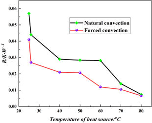
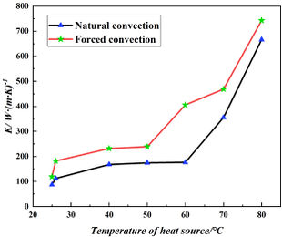
In assessing the efficacy of a heat transfer process, the thermal resistance and equivalent thermal conductivity serve as critical metrics. Within a Pulsating Heat Pipe (PHP), the fluid dynamics between the evaporator and condenser segments instigate heat transfer, thereby correlating the capillary flow and thermal resistance. An inverse relationship is observed: enhanced heat transfer correlates with diminished thermal resistance and augmented equivalent thermal conductivity. As depicted in Figure 6(a), at a heat source temperature of 25℃, the PHP remains non-oscillatory under both dissipation techniques, resulting in elevated thermal resistance. Conversely, an increase to 26℃ induces oscillation under both free and forced convection, precipitating a rapid decline in thermal resistance to 0.044K/W and 0.027K/W, respectively, with the latter exhibiting even lower values. This phenomenon is attributed to the phase transition of the working fluid, which, despite reducing the equivalent thermal conductivity, facilitates phase change heat transfer within the tube, thereby enhancing heat exchange between the hot and cold sections and consequently decreasing thermal resistance while increasing equivalent thermal conductivity, albeit still predominantly governed by conductive heat transfer.
| ||||
| Figure 6. Comparison of thermal resistance and equivalent thermal conductivity between natural convection and forced convection heat dissipation methods under different heat sources |
With the heat source temperature escalation, the working fluid’s flow velocity is expedited, bolstering phase change heat transfer and diminishing flow resistance. The thermal resistance for both dissipation methods exhibits a downward trajectory, reaching nadirs at a heat source temperature of 80℃, recorded at 0.0074 K/W and 0.0066 K/W for natural and forced convection, respectively. This trend signifies a continual enhancement in heat transfer performance, with the PHP’s thermal resistance consistently lower than that of natural convection. However, in proximity to the critical initiation threshold and during the commencement phase, the PHP’s thermal resistance reduction is gradual.
Figure 6(b) reveals that the PHP’s equivalent thermal conductivity under both dissipation methods escalates with the heat source temperature. Notably, the equivalent thermal conductivity is comparatively lower under natural convection. Despite the PHP’s superior heat transfer capabilities at elevated heat source temperatures, an ineffective dissipation method in the condenser section can compromise the device’s overall heat transfer performance. Therefore, employing forced convection for heat dissipation can enhance the condenser section’s cooling efficacy, thereby significantly improving both the PHP’s heat transfer capabilities and the device’s overall thermal performance.
4. Conclusions
In the present study, a comprehensive comparative analysis was conducted on the thermal transfer characteristics of an asymmetrically structured pulsating heat pipe (PHP) heat exchanger, considering varying heat source temperatures under both natural and forced convection scenarios. This analysis encompassed startup behaviors, operational dynamics, and thermal efficiency. The ensuing conclusions are delineated as follows:
(1) At the lower thermal thresholds of 25℃ and 26℃, PHP channels exhibit no oscillatory behavior, irrespective of the dissipation method employed, with thermal conduction being the predominant mode of heat transfer. Specifically, at 25℃, the asymmetric PHP structure remains static, whereas at 26℃, a subdued oscillation is observed under both natural and forced convection, designating 26℃ as the vibrational onset temperature for the asymmetric PHP structure.
(2) Regardless of the dissipation approach, the asymmetric PHP structure initiates localized channel activity at a heat source temperature of 40℃. As the temperature escalates, the PHP transitions into a stable mass circulation flow state characterized by oscillations. Channels with shorter lengths within the asymmetric PHP structure facilitate quicker initiation, allowing the working fluid to achieve a stable oscillatory state more readily. Channels where the evaporation section supersedes the condensation section in size can significantly curtail the startup duration. Conversely, longer channels necessitate higher heat source temperatures for activation, yet exhibit superior oscillatory effects at elevated temperatures. Under forced convection, the asymmetric PHP structure demonstrates accelerated startup velocities, reduced initiation temperatures, and more pronounced oscillatory behaviors compared to natural convection.
(3) The asymmetric PHP structure experiences oscillations of varying amplitudes and frequencies as the heat source temperature increases, regardless of the heat dissipation method. The driving force behind the working fluid’s flow within the tube stems from the pressure differential induced by thermal input, thereby intimately linking the oscillation characteristics and flow patterns of the working fluid to the heat input. The flow rate of the working fluid dictates the frequency of temperature oscillations, while the intensity of fluid oscillations determines the fluctuation amplitude. The asymmetric channel structure’s propensity for easy initiation, coupled with the accelerated flow rate of the working fluid in localized channels, catalyzes the flow in adjacent or even the entire channel network. This promotes a hastened initiation of the PHP’s overall structure, culminating in an advanced attainment of a stable cyclic flow and oscillatory state.
(4) With the increase of heat source temperature, the thermal resistance of both heat dissipation methods shows a decreasing trend due to the increase of heat source temperature which accelerates the flow rate of the work material and enhances the phase change heat transfer, and the thermal resistance of PHP under forced convection is always smaller than that under natural convection, but the value of the thermal resistance of PHP decreases slowly near the critical region of the startup and the startup stage. The equivalent thermal conductivity of PHP under both heat dissipation methods increases with the increase of heat source temperature, and the equivalent thermal conductivity under natural convection heat dissipation is lower compared to forced convection heat dissipation, so the use of forced convection heat dissipation improves the heat transfer performance of PHP and the heat exchange performance of the device.
Nomenclature
| : the total cross-sectional area of the pulsating heat pipe circulation pipeline, [m2]. |
| : the average temperature of the evaporation section, [K]. |
| : the pulsating heat pipe evaporation section and the condensing section of the average distance between the measurement point, [m]. |
| : the average temperature of the condensing section, [K]. |
| : the pulsating heat pipe evaporation section of the heat absorbed, [W]. |
| : the equivalent coefficient of thermal conductivity, W/(m·K). |
| : the heat transfer thermal resistance, [K/W]. |
Acknowledgments
This work was supported by the Jilin Provincial Department of Education Project: Research on Key Technologies for Efficient Heat Dissipation of Ultra-High Energy Density LED Lighting and the Science and Technology Development Project of Jilin Province: Research on Key Technologies for Efficient Heat Dissipation of High Power LED Lighting Equipment in Urban Public Areas.
References
[1] Pagliarini, L. Pulsating heat pipes: Critical review on different experimental techniques. Experimental Thermal and Fluid Science, 148, 110980, 2023.
[2] Dang C., et al. Investigation on thermal design of a rack with the pulsating heat pipe for cooling CPUs. Applied Thermal Engineering, 110:390-398, 2017.
[3] Qu J., et al. Experimental investigation of silicon-based micro-pulsating heat pipe for cooling electronics. Nanoscale and Microscale Thermophysical Engineering, 16(1):37-49, 2012.
[4] Deng Z., et al., Experimental study on thermal performance of an anti-gravity pulsating heat pipe and its application on heat recovery utilization. Applied Thermal Engineering, 125:1368-1378, 2017.
[5] Mahajan G., et al. Energy and cost savings potential of oscillating heat pipes for waste heat recovery ventilation. Energy Reports, 3:46-53, 2017.
[6] Sarafraz M.M., Hormozi F. Experimental study on the thermal performance and efficiency of a copper made thermosyphon heat pipe charged with alumina–glycol based nanofluids. Powder Technology, 266:378-387, 2014.
[7] Yousefi T., et al. Experimental investigation on the performance of CPU coolers: Effect of heat pipe inclination angle and the use of nanofluids. Microelectronics Reliability, 53(12):1954-1961, 2013
[8] Huo Y., et al. Simulation study on thermal performance of two turns helium cryogenic oscillating heat pipe for superconducting accelerator. Radiat Detect Technol Methods, 7(3):427-434, 2023.
[9] Sagar K.R. Novel condenser based cryogenic pulsating heat pipe: Investigations on influence of geometrical parameters. Cryogenics, 126, 103543, 2022.
[10] Liu S., et al. Experimental study of pulsating heat pipes filled with nanofluids under the irradiation of solar simulator. Energies, 15, 9153, 2022.
[11] Kargar Sharif Abad H., et al. A novel integrated solar desalination system with a pulsating heat pipe. Desalination, 311:206-210, 2013.
[12] Burban G., et al. Experimental investigation of a pulsating heat pipe for hybrid vehicle applications. Applied Thermal Engineering, 50(1):94-103, 2013.
[13] Mito T., et al. Development of highly effective cooling technology for a superconducting magnet using cryogenic OHP. IEEE Trans. Appl. Supercond., 20(3):2023-2026, 2010.
[14] Han X., et al. Review of the development of pulsating heat pipe for heat dissipation. Renewable and Sustainable Energy Reviews, 59:692-709, 2016.
[15] Nikolayev V.S. Effect of tube heat conduction on the single branch pulsating heat pipe start-up. International Journal of Heat and Mass Transfer, 95:477-487, 2016.
[16] Rudresha S., et al. Experimental investigation and influence of filling ratio on heat transfer performance of a pulsating heat pipe. Thermal Science and Engineering Progress, 38, 101649, 2023.
[17] Jang D.S., et al. Thermal performance characteristics of a pulsating heat pipe at various nonuniform heating conditions. International Journal of Heat and Mass Transfer, 126:855-863, 2018.
[18] Wu M., et al. Experimental study on the effects of filling ratios on heat transfer characteristics of liquid metal high-temperature oscillating heat pipes. International Journal of Heat and Mass Transfer, 209, 124153, 2023.
[19] Mameli M., et al. Thermal response of a closed loop pulsating heat pipe under a varying gravity force. International Journal of Thermal Sciences, 80:11-22, 2014.
[20] Li M., et al. Theoretical analysis of start-up power in helium pulsating heat pipe. IOP Conf. Ser.: Mater. Sci. Eng., 171, 012102, 2017.
[21] Wang J., Bai, X. The features of CLPHP with partial horizontal structure. Applied Thermal Engineering, 133:682-689, 2018.
[22] Chen T., et al. A novel triangular pulsating heat pipe with enhanced heat transfer performance for building energy efficiency. Case Studies in Thermal Engineering, 49, 103286, 2023.
[23] Lee Y.J., Kim S.J. Experimental investigation on the effect of transverse grooves in a channel on the thermal performance of a flat-plate pulsating heat pipe. International Journal of Heat and Mass Transfer, 218, 124759, 2024.
[24] Ebrahimi M., et al. Experimental investigation of the thermal management of flat-plate closed-loop pulsating heat pipes with interconnecting channels, Applied Thermal Engineering, 90, 838-847, 2015.Document information
Published on 21/05/24
Accepted on 09/05/24
Submitted on 22/04/24
Volume 40, Issue 2, 2024
DOI: 10.23967/j.rimni.2024.05.005
Licence: CC BY-NC-SA license
Share this document
claim authorship
Are you one of the authors of this document?
