Abstract
Many of the engineering problems are analyzed using numerical methods such as the finite element (FEM) whose results provide a basis to make basic decisions regarding the design of many important works. It is commonly accepted that FEM computations are reliable; however, the results may be affected by the configuration of the finite element mesh to simulate the medium to be analyzed, this is particularly true when the internal and external boundaries are time dependent, as is the case of soil consolidation. Accordingly, a thorough investigation was carried out with the main purpose of eliminating this shortcoming. The main steps to carried out the development of the innovative geometric procedure to automatically refine finite element tetrahedra-type (3D) are described. This geometric algorithm is based on the theory of fractals and is a generalization of the algorithm for triangular element finite element meshes (2D) [1,2]. This paper presents the fundaments of this new algorithm and shows its great approximation using 3D close form solutions, and its versatility to adapt the original Finite Element Mesh when the load boundary conditions are modified (Neumann conditions).
Keywords: Finite element analysis, remeshing algorithm, adaptive method, civil engineering, geotechnics, numerical analysis
1. Introduction
It is acknowledged that the natural basic element to discretize complex 3D continuum media are the tetrahedral-shaped elements. Having this in mind the goal of this paper is to present the development of an algorithm for 3D finite element meshes that draws principles of the theory of fractals.
The finite element method is a powerful, practical and versatile numerical analysis tool for solving differential equations through continuum discretization, but its efficiency and effectiveness can be notably hampered if local or total mesh refinements during the analyses are made manually, which can likely lead to continuum discretization blunders. As it is well known, the accuracy of finite element calculations depends on how well the mesh mimics the continuum, particularly where abrupt changes in the material properties originally existed or developed due to local material plastization of one or a number of fine elements. Likewise, the mesh has to be fine enough to accurately describe the geometry of the problem constituents (i.e., sharp corners of soil-structure problems) and capture abrupt changes in local stress and/or strain gradients stemming from material heterogeneities (i.e., soil-concrete interfaces of embedded foundations).
Finite element approximations improve either by reducing the size of finite elements (refining specific zones of the mesh by automatic remeshing) or increasing the order of the polynomial shape function. (Evidently, a combination of these two approaches is also a viable alternative). The former is used in this paper, by means of the adaptive algorithm presented herein. At present time, several approaches exist to generate and refine locally 3D and 2D finite element meshes [3,4]. Furthermore, some mesh generation techniques such as the Delaunay triangulation [5,6], the advancing front approach [7], mesh generation using contours [8], the coring technique [9], the “quadtree” technique [10], among others, are available for automatically generate gradation triangular-element meshes [11]. Moreover, a number of studies focused on modelling contact regions [12], also to avoid large aspect ratios in order to maintain an adequate approximation level [13] and to compute accurate solutions when large mesh distortions develop during computations [14]. In addition, algorithms for refinement/derefinement of nested meshes using fractal concepts and iterated function systems (IFS) have been proposed [15-18]. Evolution problems have been addressed elsewhere [19]. In addition, the skeleton based refinement (SBR) has been used to refine unstructured meshes for 2D and 3D problems [20]. Dunyach et al. [21] proposed a curvature-adaptive isotropic remeshing technique for real-time mesh deformation. You et al. [22] developed an adaptive remeshing procedure for finite element analysis of heterogeneous materials. Adaptive finite element techniques have been advanced and used for more than twenty years. Adaptive procedures try to automatically refine, coarsen, or relocate a mesh and/or adjust the basis to achieve a solution having a specified accuracy in an optimal fashion. Most known methods of adaptive mesh refinement include: a) r-method (refines locations of nodes), b) h-method (refines an element into multiple elements, and c) p-method (refines polynomial order of element shape functions). Adaptive remeshing implies the adjustment of mesh control parameters based on error estimates or attributes, deleting an existing mesh, and regenerating a new mesh. Adaptive remeshing is a geometry/topology based process and is commonly performed as a pre/post-processing function.
Broadly speaking, any remeshing procedure must include the following features:
(i) A mesh-refining criterion related to an error estimator of the calculation accuracy, or to the local distortion mesh or to the spatial discretization of the boundaries.
(ii) A mesh generator assuming element size distribution inside the domain or around its boundaries depending on the chosen error estimator.
(iii) A transfer procedure that carries out a mapping of history dependent variables from the old to the new mesh for each remeshing step.
The 3D algorithm included herein is a generalization of the 2D algorithm [1], where the triangular elements (2D) are expanded to tetrahedral elements (3D). Such changes imply from the way in which the elements interact, since now there are two types of neighboring elements (face and edge), to the number of elements obtained after partitioning.
The algorithm integrates a number of features arranged in a “software” with modular structure, which makes it a versatile tool capable of 1) Maintaining all problem initial symmetries and 2) simulating nonlinear analysis, using the proper material constitutive model.
To the authors´ knowledge, this algorithm is one of the few available refining procedures considering innovative concepts educed from fractal theory. As has been shown earlier for the 2D case [1,2], the algorithm provides almost identical results regardless of mesh initial geometrical characteristics and of its roughness.
To demonstrate the algorithm’s reliability, the procedure is assessed comparing the stresses it yields with those computed with the closed form solutions of a flexible shallow square slab footing on the surface of a soft clayey homogeneous deposit, considering first only vertical loading and then under vertical and horizontal loading. From the results included herein it becomes clear the importance of adapting the mesh to the ongoing load boundary conditions.
It is worth mentioning that currently there are commercial and non-commercial software very useful to build finite element meshes in 2D and 3D of excellent quality, e.g., Onelab [23], Agros2D [24], Fenics Project [25], but they do not automatically refine the region exceeding the stress-strain behavior thresholds and hence, the user must indicate where the mesh should be refined according to his experience. If the remeshing is carried out manually, mishaps in defining the topology of the small elements are likely to occur, or the refining is not sufficient to obtain reliable results.
1.1 The tetrahedron
As it is known, tetrahedral elements are used to discretize media that can later be analyzed by some numerical method like the Finite Element. As will be shown below, the tetrahedral element allows a region to be refined locally without inducing an important propagation of the refinement outside of the zone being refined. Accordingly, in this work the tetrahedral element is used to refine finite element meshes where needed at different local zones.
In this section some of the geometric characteristics of the tetrahedron are presented as background information to make easier the understanding of developing the parameter quality indicator for qualifying the degeneration of the tetrahedron. This parameter is used to define the skewedness of the tetrahedral elements that integrate the refined finite element mesh.
1.2 Main geometric characteristics
Let , , , and be points in that are not contained in one plane. Denoting by T the tetrahedron with vertices and (Figure 1), forming the simplest closed convex polyhedron, which has 4 triangular faces and 6 edges. The volume of can be calculated by the following expression:
|
|
(1) |
|
|
(2) |
Defining:
|
|
(3) |
where is the radius of the circumscribed ball into , where is the surface of the boundary of .
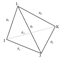
|
| Figure 1. Tetrahedron |
The radius of the circumscribed ball about T can be computed as [26,27]:
|
|
(4) |
where
|
|
(5) |
In the above formula and are the Euclidean lengths of opposite edges of for :
, , , , ,
The dihedral angles of a tetrahedron are the six angles between each pair of faces of . They are defined as the complementary angles of outward unit normal to those facets and can be calculated by means of the inner product [27]:
where and are the outward unit normal of particular faces.
It is common in FE analysis to qualitatively distinguish between so-called “well-shaped” (i.e., close to regular) tetrahedra and “badly-shaped” ones (i.e., close to degenerate). Some classifications of badly-shaped tetrahedra are given in [27]. The degree of degeneration of a tetrahedron T is often measured in terms of the quality indicator [28]:
|
|
(6) |
Tetrahedra with quality indicator near 1 are almost regular, whereas those with near 0 are nearly degenerate.
1.3 Tetrahedron subdivision
The method of subdivision of tetrahedral elements proposed in this work consists of three categories: the first establishes the sectioning of a central element, the second consists in the sectioning of a neighbor-face element and the third induces a partition of a neighbor-edge element. Different tetrahedral sectioning techniques can be found elsewhere [11,27,29]. The proposal in this paper makes a combination of three forms reported in the literature [27]: red, green and red-green, for the central elements, neighbor-face and neighbor edge respectively as seen later.
2. Algorithm for tetrahedral elements refinement: core philosophy
The procedure proposed herein is purely geometric (branded ARFEM3D-Automatic Refinement of Finite Element Meshes-3D; the software may be obtained directly from the senior author) and was inspired by fractal technology, i.e., from a given fractal figure one is capable of subdividing it in as many as desired self-similar figures having much smaller dimensions.
The algorithm uses the Sierpinski’s idea that consists in dividing subsequently a tetrahedral element following specific rules [1,2], as graphically indicated in Figure 2. Herein are presented the key aspects of a new procedure to refine finite element tetrahedral meshes as problem-solving computations proceed. The main difference between the refinement process proposed herein and the Sierpinski tetrahedron is that any tetrahedral element that does not satisfy the threshold criterion is not extracted but refined until the threshold criterion is fulfilled.
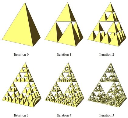
|
| Figure 2. Sierpinski tetrahedron generation |
3. Algorithm for remeshing tetrahedral elements: procedure
In FE analysis and computation, one needs sequences (infinite or finite) of partitions that have certain properties. One can define various kinds of “well-shapedness”, usually called regularity, in the sense that certain properties of the tetrahedral elements are supposed to hold uniformly over all partitions of the family [27].
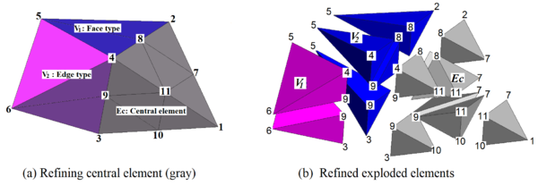
Consider the section mesh of Figure 3(a), conformed by three tetrahedral elements. Now assume that the gray-shaded element (nodes 1, 2, 3 and 4) does not fulfill the (i.e., octahedral stress) threshold criterion and hence it should be refined. To this end, it is precise to consider the contiguous tetrahedral elements that delimit the zone to be refined. In Figure 3(a), the area to be refined is defined by numbering the elements and nodal points. It is noted that there are two types of element neighboring the central one: the first is of the "face" type, since it shares one of its four faces with the central element (element in Figure 3, conformed by nodes 1, 2, 4 and 5), and the second is of the "edge" type, because it only touches the central element at one of its six edges (element of Figure 3(b), formed by nodes 2, 4, 5 and 6).
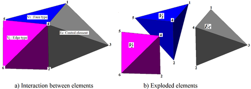
|
| Figure 3. Region to be refined: central element Ec and its neighbors (face type) and (edge type) |
Therefore, when the central element is fragmented, the subdivision of neighboring elements will be induced, according to its type. Refinement of the central element is carried out bisecting its four edges generating eight tetrahedrons (), as shown in Figure 4(b), wherein the generated elements have been contracted and colored to show in detail the fragmentation of the central element . Note that the unrefined central element is now integrated by eight self-similar smaller elements such that . In doing this partition one introduces six nodal points (between and ), (between and ), (between and ), (between and ), (between and ) and (between and ), which are located at mid-distances among existing nodal points , , and , respectively. These new nodal points violate the connectivity rule of the finite element. To overcome this problem, one has to refine locally the mesh by subdividing neighbor elements ( and ) as indicated in the inset of Figure 5, which generates four new tetrahedral elements from and , and two tetrahedral elements from and , which implies that and . It is important to note that refinement of the initial central triangle (Figure 4) compels to refine also all adjacent tetrahedral elements (Figure 5), but the algorithm is properly designed to preclude the refinement be extended to nearby tetrahedral elements. This is obviously advantageous because when the refinement of a large mesh is required at different zones, only the elements at each zone will be involved; hence, the remeshing task is carried out efficiently. However, each of the zones where the integrating elements were refined can be refined further within the constrained zone. In addition, notice that the algorithm produces a kind of element-refining implosion and all new tetrahedral elements are self-similar. At all times it is verified that the volumes before and after the partition do not change, hence the following identities must be fulfilled.
Central element volume:
|
|
(7) |
Neighbor element volume:
|
|
(8) |
Neighbor element volume:
|
|
(9) |
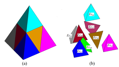
|
| Figure 4. (a) Central element after first iteration. (b) Shrink elements generated |
|
| Figure 5. Central and adjacent elements after first iteration. in blue and in magenta. Central element in gray |
So far, we have considered that there is only one central element. However, there may be situations when it is advantageous to consider two or more adjacent tetrahedral elements as the central tetrahedron from which refinement starts. To accommodate these situations, we introduced the following rules:
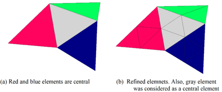
Rule 1: If two elements (red and gray contours, in Figure 6(a) share one of their faces, both are considered central elements and remeshing will proceed as if each element was independent. Notice that only side-to-side or face-to-face adjacent elements to are subdivided. Figure 6(b) shows graphically such procedure.
| Figure 6. Remeshing considering two adjacent central elements |
Rule 2: If two or more elements (i.e., red and blue tetrahedra, in Figure 7(a) are adjacent to other common neighbor element, all three are considered central as depicted in Figure 7(b) and mesh refinement follows Rule 1. By deducting reasoning, if elements are adjacent each of them can be considered central and hence the refinement Rule 1 applies likewise.
|
| Figure 7. Remeshing considering three adjacent central elements |
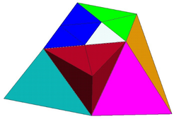
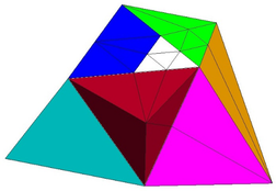
It is important to mention that the partitioning of central elements may lead to adjacent tetrahedral elements rather skewed, as portrayed in Figure 9. To avoid the formation of much skewed tetrahedral elements within the mesh; the algorithm includes a tool to analyze all the tetrahedra according to their side ratios. This technique is illustrated in Figure 10. Considering as initial mesh the one shown in Figure 8 and assuming the white element has to be refined, the resulting mesh would be the one indicated in Figure 10 It is seen that sharper elements result from the fractioning the elements next to the central selected element.
|
| Figure 8. Tetrahedral element to be refined |
|
| Figure 9. Elongated elements due to refinement of central element |
The algorithm avoids the formation of highly distorted elements by performing a previous analysis of the degree of degeneration () of all tetrahedral elements. If the specified shape ratio and the element exceed specified thresholds, then these elements are considered central elements as indicated in Figure 10. The procedure follows until none of the new elements violates the element ratio, as graphically depicted in Figure 10 for ratios equal to 0.5. It is worth mentioning that these features improve appreciably poorly designed meshes making sure the results are meaningful. When defining the threshold ratio, it is important to have in mind that the ratio of equilateral tetrahedra is one, and all internal angles are equal among theme, and when bisected, their ratio will be greater or equal to 0.5.

|
| Figure 10. Automatic searching of elongated elements and refinement towards their elimination |
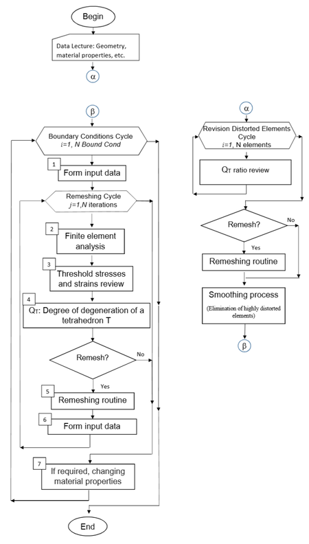
Before any finite element computations are carried out, the algorithm is applied to smooth the initial mesh to eliminate all distorted (sharp) elements as indicated by the block diagram included as inset in Figure 11. The full smooth-refining algorithm depicted in Figure 11 was coded yielding the ARFEM3D software briefly commented next.
|
| Figure 11. Flow chart of the automatic remeshing procedure |
After the initial mesh is smoothed, the automatic refining procedure begins by forming a file containing all the initial characteristics of the mesh and characteristics of the problem itself (i.e., boundary conditions, material properties, present and future boundary conditions, etc.).
Having defined the initial conditions of the problem, a loop where the boundary conditions are modified, is initiated (From to NBoundCond). For each boundary condition, a stress-strain finite element analysis is carried out and at the end of each cycle of this loop, material properties can be modified to account, if required, for nonlinear materials characteristics. Once the new stress state of the full mesh is known, a search of elements to be refined begins according to the threshold initially specified. The element-refining cycle is carried out until none of the elements surpasses the threshold specified.
It is worth stressing the fact that the finite element refining proceeds whenever the threshold is exceeded; to make element-mesh discretization adequate so the problem at hand is properly modeled. This element refinement leads to a smoothed mesh that minimizes the inclusion of spurious stiffnesses and numerical inaccuracies in the finite element computations. As the block diagram of Figure 11 indicates, these tasks are performed within every cycle until the number of iterations defined are completed. Accordingly, every time a new mesh is generated, the new stress-strain state is computed. Once the remeshing cycle is completed, the boundary conditions if required are modified and the above-mentioned procedure is performed all over again.
4. Assessment of the algorithm: vertical and then vertical plus horizontal loading on a flexible superficial slab foundation
In this chapter, the algorithm developed and shown in this paper is compared in terms of vertical stresses and vertical displacements along of a number of profiles to the results computed with the corresponding close form solutions. These comparisons show that whenever the problem under analysis is not properly discretized (although at deep scrutineers seemed otherwise) the results more often than not will be misleading and hence the designs might leave much to be desired.
4.1 Uniform vertical distributed load (qv) on a rectangular area
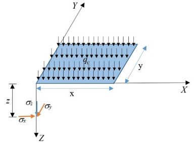
Stresses in an infinite homogeneous ground mass generated by the action of a vertical uniformly distributed load () on a rectangular flexible foundation on the ground surface (Figure 12) can be calculated under a corner of the loaded surface using the following expressions [30,31]:
|
|
(10) | ||
|
|
(11) | ||
|
|
(12) | ||
|
|
(13) | ||
where are the dimensions of the rectangle loaded uniformly, is the depth at which the stresses are calculated and is the Poisson ratio.
|
| Figure 12. Vertical uniformly distributed load () on a rectangular ground foundation on a homogeneous infinite medium |
4.2 Uniform horizontal distributed load (qh) on a rectangular area
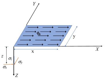
Vertical normal stresses in an infinite ground mass generated by the action of a uniform horizontal distributed load () on a rectangular area (Figure 13) can be calculated under a corner (of loaded surface) to z depth using the following expressions [31]:
|
|
(14) |
where
|
|
(15) |
|
|
(16) |
|
|
(17) |
where is the large of surface loading, the width of surface loading and is the depth.
|
| Figure 13. Horizontal uniformly distributed load () on a rectangular ground foundation on a homogeneous infinite medium (as in Figure 12) |
4.3 Analytical versus FE solutions with and without remeshing
In this section, the analytical solution for the flexible rectangular superficial foundation is compared with the finite element solutions obtained in terms of vertical stresses along the axis located in the center of the loaded area. First, the analyses using a coarse mesh and a fine mesh are presented. Then the refinement process is applied to the coarse mesh. The foundation examples presented herein have unit loading, kPa (3000 kg/m):
|
|
(18) |
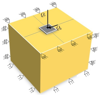
where is the vertical total external foundation load, m are the width and the length of the slab and is the unitary load. Soil material properties: Young´s modulus = 1999 kPa (203943 kg/m) and Poisson´s ratio = 0.5. The magnitude of the horizontal load () added in a second stage of the analysis, to modify the loading boundary conditions was assumed equal to (Figura 14).
|
| Figure 14. Loading on a rectangular area. For plotting simplicity, the vertical and horizontal uniformly distributed loads over the full foundation area are represented by and |
4.4 Applying remeshing fractal algorithm
In order to ensure that zones with stress-state singularities are detected and refined accordingly, the threshold criteria used in the examples included herein, were 0.60, 0.70 and 0.80 of the octahedral shear strength for refinement iterations 1, 2 and 3, respectively; that is, the element will be refined if:
|
|
(19) |
where is the octahedral shear stress computed, the octahedral shear strength and the refinement of the mesh
The maximum shape ratio for all examples included herein was defined to be 0.5.
In order to show the contours of displacements and stresses and as well as the refinement that is generated inside the mesh, only half of the media that supports the superficial foundation is presented.
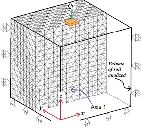
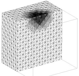
Figure 15(a) depicts the original finite elements ensemble that establish initial mesh, and Figure 15(c) shows the finite element mesh obtained after three iterations starting from the initial mesh. It can be seen that the mesh was refined in zones near the boundary where the load is applied, this concurs with the well-known fact that higher stresses concentrate near the boundary loading. Notice that far away, from where the load is applied, the initial mesh remains unchanged, meaning the loading influence on the continuum stress-state is not appreciable. One of the advantages of the remeshing performed by the algorithm is that the size of the finite elements increase smoothly and their aspect ratio () is kept larger than the given criterion (0.5 for this example) and free of distorted elements, hence avoiding abrupt size transitions that may cause numerical errors.
|
|
| (a) | (b) |
|
|
| (c) | (d) |
| Figure 15. Slab on the ground surface, vertical load (kgf/m2). Only half of the analyzed region is shown (in Figure 14 the full region is shown) | |
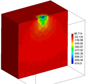
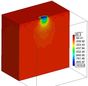
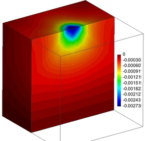
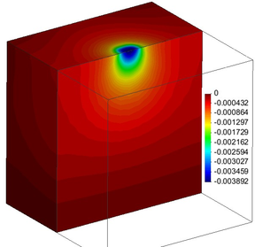
From the analyses of the four meshes depicted in Figure 15 one can plot the normal vertical stress bulbs. The comparison of these stress bulbs in Figure 15(b,d), clearly shows that the locally refined mesh brings out better defined stress bulbs. Particularly at the zones where larger stress (strain) gradients are developed (i.e. near the loaded area): while the bulbs in Figure 15(b) are rather misty, those in Figure 15(d) are much more clearly defined. Furthermore, in terms of displacements, comparison of Figure 16(a) versus Figure 16(b), supports this statement.
|
|
| (a) | (b) |
| Figure 16. Bulbs of vertical () displacements distribution (m). Half of mesh | |
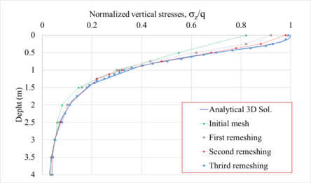
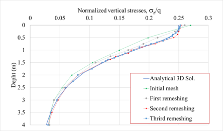
To further show the reliability of the remeshing algorithm advanced in this paper, Figures 17 and 18 show the normalized () vertical stress profiles obtained from the initial, first, second and third refined meshes, along the center (axis 1) and corner of the slab. It can be seen that the results are fine-tuned using the local automatic remeshing algorithm.
|
| Figure 17. Vertical normal stress profiles (normalized), along axis 1 |
|
| Figure 18. Vertical normal stress profiles (normalized), below a corner of the flexible slab |
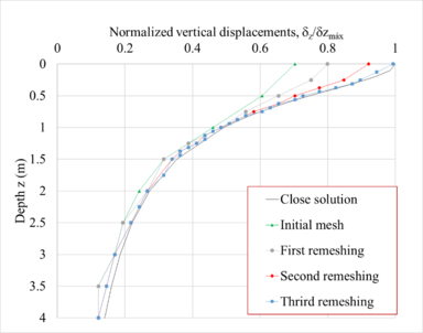
Similarly, Figure 19 shows the normalized vertical displacements (eq. (20)) profiles, obtained from the initial mesh, first, second and third refined meshes, under the center of the slab. Again, it is observed that the results are fine-tuned using the remeshing algorithm advanced in this paper
|
|
(20) |
where is the vertical displacement to depth and is the maximum vertical displacement computed with the analytical close form solution. It is seen that the ground settlements computed with the initial FE mesh disagree significantly with those calculated using the close form solution. On the contrary, the settlements computed with the FE using the remeshing algorithm reproduce better the theoretical settlements. In fact, they are practically equal for the mesh obtained after three remeshing iterations. All the results shown above indicate the great importance of properly discretizing the continuum in order to obtain reliable results.
|
| Figure 19. Vertical displacements profiles (normalized), axis 1 |
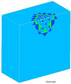
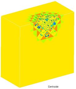
Due to the nature of the proposed sectioning, the quality of the elements generated in the refinement decreases as the refinement is performed, this is unavoidable. However, as the size of the elements is reduced, and as the refinement progress, the loss of quality is minimized to only some very small elements, as can be seen in Figure 20 . In addition, as can be seen in the graphs of Figures 17-19, which compare the results obtained by applying automatic refinement with the analytical solution, it is shown that even with the loss of quality of some elements, the accuracy in the results increases. This is because, the density of elements grows and is concentrated inward (implosion), which minimizes the error induced by those elements with low quality . From the results obtained, it is concluded that the low quality of some elements in the refined mesh does not induce loss of precision in the results, so the value of is acceptable.
 |
 |
| (a) First refinement | (b) Third refinement |
| Figure 20. parameter | |
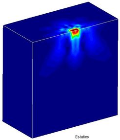
In addition, the relative error reached through the iterations in Figure 21 can be seen; in the example presented here, a relative error of less than 10% is reached. The relative error for each node is calculated by equation (21):
|
|
(21) |
where, is the displacement in node , iteration , the displacement in node , iteration and the maximum displacement, iteration .
 |
 |
| (a) First refinement | (b) Third refinement |
| Figure 21. Relative error | |
4.5 Load boundary condition effects on FE results
It is common practice that finite element analyses be carried out keeping unchanged the original mesh defined for analyzing the problem at hand, regardless of the potential time variations of loading boundaries and/or stress states (i.e. dam reservoir filling, water withdrawal from saturated soils leading to their consolidation, etc.). It is worth mentioning that Ferragut and Plaza [19] recognized this shortcoming and studied this issue for heat time-variation in plates. Herein, to show the influence of modifying the load boundary conditions on the induced shear stresses, the loading condition of the slab on the ground surface example was modified by adding a horizontal load. Therefore, the load boundary condition includes vertical (existing) and horizontal (added) loading, where
|
|
(22) |
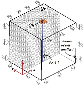
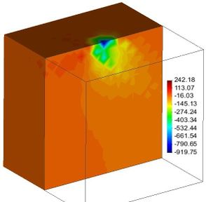
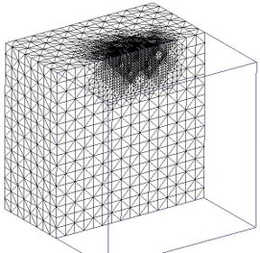
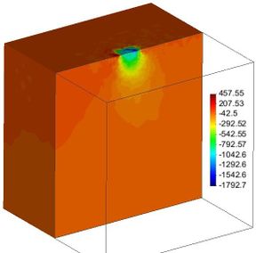
In this simple example, the initial mesh (Figure 22(a)), half mesh visualized) was refined considering both vertical and horizontal loads, which after three iterations the half mesh in Figure 22(d) was obtained. These figures clearly show that the meshes used to compute the stress-strain states are not alike: while the mesh in Figure 22(a) is symmetrical with respect to the central vertical axis and homogeneous, the mesh (refined according to the load boundary conditions) depicted in Figure 22(d) is clearly asymmetric with respect the same axis and also results inhomogeneous. Actually, it can be assured that the resulting mesh is tailored to fit the loading conditions, which is a very important aspect to be accounted for. It is important to stress the fact that most FE actual codes do not consider this mesh modification. Hence, for problems where their boundary and stress-strain conditions are time-dependent, one can seriously doubt on the representativeness of the results and henceforth the quality of designs based on them.
|
|
| (a) | (b) |
|
|
| (c) | (d) |
| Figure 22. Slab on the ground surface. Half mesh visualized. Stresses in kg/m | |
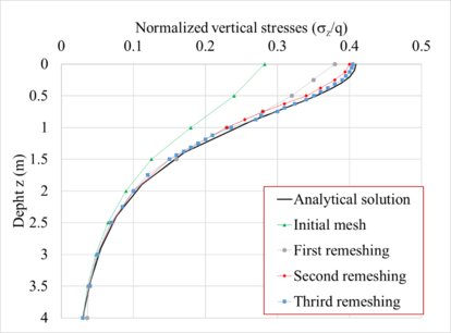
The remeshing-dependence of the load boundary conditions is clear. Local refinement allows to define more clearly the stress contours. These results indicate that the finite element meshes should be modified according to the ongoing load boundary conditions. In Figure 23 the normalized normal stresses computed along axes below the corner (indicated in Figure 22(a) using the initial mesh and the meshes obtained after three iterations are compared with the closed form solution.
|
| Figure 23. Comparison of normalized normal vertical stresses profiles |
It is clear that the remeshing considering the present loading conditions has a significant effect from the ground surface down to a depth equal to the foundation width. Therefore, the results obtained in this investigation seem to indicate that whenever the elements of the initial mesh are not modified as a function of the ongoing load conditions, the results could lead to biased conclusions regarding the problem under consideration. Hence, meshes defined for particular loading conditions are not generally suited for the same problem whenever the load boundary conditions (and hence the stress state) are modified.
5. Conclusions
The results of the simple examples included in this paper clearly indicate that there is a close relationship between the load boundary conditions and the mesh needed to obtain trustworthy results. The impact that this issue can have on actual problems throughout their life expectancy can undoubtedly be larger than shown in this paper, whenever the problem complexity increases. Usual problems that lead to this condition are, for example, consolidation of a clay soil deposit (without or with drains to accelerate the consolidation, and even worse when water withdrawal from the deposit is underway, urban and in general road tunnels, any type of earth and rockfill dams, etc.).
The results included in this paper show that the algorithm can refine the elements maintaining their shape ratio under a specified threshold, same results are obtained when various thresholds are considered. Accordingly, finite element users can define very rough meshes (even not worrying about zones of stress/strain concentrations) and the proposed algorithm will adequate the mesh elements to achieve a reliable solution of the particular problem.
The discretization of the refined mesh is dependent on the boundary conditions, as well as the loading conditions, as it was shown in the Section 4.5. Henceforth, it can be concluded that if the load conditions in a problem change, the mesh used must be modified accordingly.
It could be argued that the automatic remeshing proposed in this paper allows optimization of the computing resources because only some areas of the analyzed medium are refined, avoiding the use of overly dense meshes defined on the basis of previous experiences. This may become important when an extended program of parametric analyses of a particularly complex problem is needed.
Finally, it is worthwhile to mention that where sharp edges of stiff material interact with softer materials, the size of the elements to properly discretize the continuum in the surrounding area is so small that it would be practically impossible to carry out this task manually without mishaps.
Acknowledgements
This work was supported by UNAM-PAPIIT <IT102719>
Authors wish to thank “Dirección General de Cómputo y de Tecnologías de Información y Comunicación, UNAM” for providing computer time in the Miztli system.
References
[1] Hermosillo A., Romo M., Magaña R., Carrera J. Automatic remeshing algorithm of triangular elements during finite element analyses. Revista Internacional de Métodos Numéricos para Cálculo y Diseño en Ingeniería, 34(1), 4, 2018. https://doi.org/10.23967/j.rimni.2017.5.003
[2] Hermosillo A., Romo M., Magaña R. and Carrera J. Adaptive refining method for 2D triangular-element meshes for finite element analyses. Serie Investigación y Desarrollo 702, Instituto de Ingeniería, UNAM, 2018.
[3] Hu Y., Randolph M.F. H-adaptive FE analysis of elasto-plastic non-homogeneous soil with large deformation. Computers and Geotechnics, 23:61-83, 1988.
[4] Belitchko T., Tabaraa M. H-Adaptivity finite element methods for dynamic problems, with emphasis of location. International Journal of Numerical Methods in Engineering, 36:4245-4265, 1993.
[5] Lo S.H. Delaunay triangulation of non-convex planer domains. International Journal for Numerical Methods in Engineering, 28(11):2695–2707, 1989.
[6] George P.L., Hermeline F. Delaunay’s mesh of a convex polyhedron in dimension d. Application to arbitrary polyhedra. International Journal for Numerical Methods in Engineering, 33:975–995, 1992.
[7] Lo S.H. A new mesh generation scheme for arbitrary planar domains. International Journal for Numerical Methods in Engineering, 21:1403–1426, 1985.
[8] Lo S.H. Automatic mesh generation and adaptation by using contours. International Journal for Numerical Methods in Engineering, 31:689–707, 1991.
[9] Lo S.H., Lau T.S. Generation of hybrid finite element mesh. Microcomputers in Civil Engineering, 7:235–241, 1992.
[10] Shephard M.S. Approaches to the automatic generation and control of finite element meshes. Applied Mechanics Reviews, 41:169–185, 1988.
[11] Lo S.H. Finite element mesh generation and adaptative meshing. Prog Struct. Engng. Mater., 4(4):381-399, 2002. doi: 10.1002/pse.135
[12] Oysu C. Finite element and boundary element contact stress analysis with remeshing technique. Applied Mathematical Modelling, 31:2744–2753, 2007.
[13] Castelló W.B., Flores F.G. A triangular finite element with local remeshing for the large strain analysis of axisymmetric solids. Comput. Methods Appl. Mech. Engrg., 198:332–343, 2008.
[14] Hamel V., Roelandt J.M., Gacel J.N., Schmit F. Finite element modeling of clinch forming with automatic remeshing. Computers and Structures, 77:185-200, 2000.
[15] Plaza A. The fractal behaviour of triangular refined/derefined meshes. Communications in Numerical Methods in Engineering, 12:295-302, 1996.
[16] Rivara M.C. A grid generator based on 4-triangles conforming mesh-refinement algorithms. International Journal of Numerical Methods, 24(7):1343–1354, 1987.
[17] Rivara M.C., Iribarren G. The 4-triangles longest-side partition of triangles and linear refinement algorithms. Mathematics of Computation, 65(216):1485-1502, 1996.
[18] Bova S.W., Carey G.F. Mesh generation/refinement using fractal concepts and iterated function systems, Int. J. Numer. Methods Eng., 33:287-305, 1992.
[19] Ferragut L., Montenegro R., Plaza A. Efficient refinement/derefinement algorithm of nested meshes to solve evolution problems. Communications in Numerical Methods in Engineering, 10:403-412, 1994.
[20] Padrón M.A., Suárez J.P., Plaza Á. Adaptive techniques for unstructured nested meshes. Applied Numerical Mathematics, 51:565–579, 2004.
[21] Dunyach M., Vanderhaeghe D., Barthe L., Botsch M. Adaptive remeshing for real-time mesh deformation. EUROGRAPHICS 2013 / M.A. Otaduy, O. Sorkine, 2013.
[22] You Y.H., Kou X.Y., Tan S.T. Adaptive meshing for finite element analysis of heterogeneous materials. Computer-Aided Design, 62:176–189, 2015.
[23] Alnaes M.S., Blechta J., Hake J., Johansson A., Kehlet B., Logg A., Richardson C., Ring J., Rognes M. E., Wells G.N. The FEniCS Project Version 1.5. Archive of Numerical Software (3), 2015. https://fenicsproject.org/
[24] Fiedler M. Geometrie simplexu v I. Casopis Pêst Mat., 79(4):297-320, 1954.
[25] Onelab. Open Numerical Engineering LABoratory, 2018. http://onelab.info/
[26] Karban P., Mach F., Kůs P., Pánek D., Doležel I. Numerical solution of coupled problems using code Agros2D. Computing, Volume 95, Issue 1 Supplement: 381-408, 2013. 10.1007/s00607-013-0294-4. http://www.agros2d.org/
[27] Brandts J., Korotov S., Krizek M. A geometric toolbox for tetrahedral finite element partitions. In Efficient Preconditioned Solution Methods for Elliptic Partial Differential Equations, O. Axelsson and J. Karatson (eds.), pp. 103-122, 2011.
[28] Golias N.A., Tsiboukis T.D. An approach to refining three-dimensional tetrahedral meshes based on Delaunay transformations. Internat J. Numer. Methods Engrg., 37:793-812, 1994.
[29] Gruau C., Coupez T. 3D tetrahedral, unstructured and anisotropic mesh generation with adaptation to natural and multidomain metric. Comput. Methods Appl. Mech. Engrg., 194:4951–4976, 2005.
[30] Damy J. Integración de las superficies de Boussinesq, Westergaard y Frölich, sobre superficies poligonales de cualquier forma, cargadas con fuerzas verticales uniformemente repartidas. Rev. Ingeniería, No. 1, Facultad de Ingeniería, UNAM, México, 1985.
[31] Poulos H.G., Davis E.H. Elastic solutions for soil and rock mechanics. Centre for Geotechnical Research, University of Sidney, 1991.
Document information
Published on 12/01/21
Accepted on 16/11/20
Submitted on 02/03/20
Volume 37, Issue 1, 2021
DOI: 10.23967/j.rimni.2020.11.001
Licence: CC BY-NC-SA license
Share this document
Keywords
claim authorship
Are you one of the authors of this document?
