Abstract
Optimum implant positioning and technique used for its alignment are vital parameters to improve clinical results. Visual cues and jigs are utilized in the recent surgical techniques, which lead to some errors in the flexion-extension axis identification. Surgeons have used computer-assisted surgery for the alignment of the hip, knee, and shoulder. However, there is a restricted application of this technology to the elbow. In this study, a technique was used to model a drill guide template to precisely place an implant in the bone. The computed tomography dataset was used to construct four different elbow bones, and an elbow implant was modeled. The surgical drill guides were designed based on the computed tomography data. The drill guide templates and constructed bones were fabricated, using a 3D printer. The accuracy of the surgical guides was validated experimentally. The results showed that the mean deviations between the achieved and planned positions of the hole at the bone apex and base of bones were less than those reported in previous studies in both medial/lateral and posterior/anterior positions. The low positioning errors observed in this study proposed that the implant’s location can be precisely aligned to its target using the introduced technique.
Keywords: Elbow implant, Total elbow arthroplasty, Drill guide template, Rapid prototyping, 3D printing
1. Introduction
The elbow joint complex includes three bones, namely the proximal radius, distal humerus, and proximal ulna [1,2]. Commonly, the elbow is involved in many diseases, especially rheumatoid arthritis (RA) (20% to 60% of patients). Total Elbow Arthroplasty (TEA) is used to treat patients with diseases such as osteoarthritis, posttraumatic arthritis, rheumatoid arthritis (RA), and failed reconstructive procedures of the elbow [3,4,5,6]. Compared to the knee and hip joints, the size of the elbow is quite small. During the late 1970s and early 1980s, there were unsatisfactory results of TEA performed. Scientists have modified the implant design by achieving more knowledge about the biomechanics of the elbow. There are two types of elbow implants; linked and unlinked. These implants are comprised of humeral and ulnar components. The linked implants possess a hinge that links the ulnar and humeral components to prevent dislocation [4,7,8].
Implant loosening is the most prominent complication in the TEA. Periodical physical and radiographic evaluations are the only clinical methodologies to identify implant loosening [9]. Van der Lugt et al. (2010) used conventional standardized radiographs and evaluated the migration pattern of 18 elbow implants in 8 years. Two parameters were evaluated, including implant alignment and the presence of radiolucent lines. At the extended follow-up, increased and variable migration pattern was recorded for all humeral components [10]. One of the causes of loosening is an insufficient position of the articulating axis of the elbow implant. The implant malposition results in the excessive contact and stress concentration between the polyethylene bushings. Ideally, the natural motion of the elbow joint is reproduced by the implant after TEAs. Hence, the implant flexion-extension axis must be similar to the native joint [11,12].
Critical parameters, such as implant positioning are dependent on the applied alignment technique. Sufficient placement of the implant is an essential parameter for optimal durability and functionality of the device in TEA operation. Biomechanical and anatomic considerations should be utilized for the positioning of the implant. An implant that is optimally implanted should imitate the normal motion to reduce the risk of loosening [13]. Even a small malposition of the components can cause loosening, early wear, and poor function [14,15]. Jigs and visual cues are used in recent surgical techniques for TEA and estimation of the native flexion-extension axis of the elbow. Geometric centers within the capitellum and trochlea assist in determining the flexion-extension [16,17]. Some deviations and errors of up to 10° may happen during the flexion-extension axis identification. Modern implants have improved the survival rates, however, loosening is still the main problem [18,19]. Therefore, both surgical technique and implant design should be improved to attain better results.
Computer-assisted surgery has proved a valuable outcome in surgical disciplines. Surgical guides have been used to enhance the accuracy of implant placement [20,21]. The ability of surgeons to place an implant accurately is increased through surgical methods that are assisted by the computer. It has been reported that using computer-aided methods improves implant alignment in comparison to conventional techniques [19]. Determining the rotation axes of the elbow before and after the surgery can demonstrate the critical role of implant location in terms of loosening. There is a potential for computer-assisted surgery (CAS) to be an excellent assistant to invasive surgery in various orthopedic areas [22,23,24]. A large number of reasons such as implant malalignment may reduce component loosening. Since there is no potential for controlling and limiting the patient’s daily activities after the operation, there should be true component positioning to prevent loosening.
Compared to the arthroplasty of the hip and knee, the elbow implant is less successful. Misalignment of components may be the reason. Previous studies had demonstrated the reliability and accuracy of computed tomography (CT) scanning and rapid prototyping (RP) techniques such as 3D printing [25,26,27,28]. The scarcity of elbow replacements compared to that of the hip and knee has deterred researchers from making statistical correlations between clinical outcomes and implant alignment. Therefore, very little is known about the computer-aided design (CAD) and computer-aided manufacturing (CAM) surgical guide for the elbow joint. This is a call for further studies and investigations. In this study, the model of humerus bones was constructed from a CT dataset.
A linked elbow implant was modeled, using CAD and computer-aided engineering (CAE) software packages. The surgical guides were designed based on a patient’s CT dataset, using an image processing software. Furthermore, a surgical drill guide was developed to lead drilling in the proper direction. The modeled implant was placed in the bones, using surgical guides in the image processing software. The constructed bones and surgical guides were fabricated, using a 3D printer. Experimental validation was carried out to determine the precision of the surgical guide for surgery. It was hypothesized that the introduced technique using CAD and 3D printing for humeral implant positioning would lead to greatly precise positioning.
2. Materials and methods
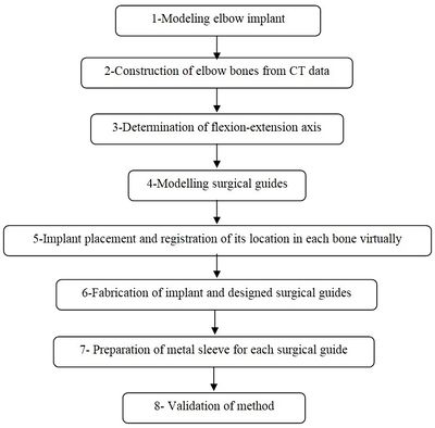
A CT-based model allows accurate placement of an implant, resulting in the inserting of the implant in the most strategically valid locations, using 3D virtual analysis prior to the operation. Virtual implant planning is driven by the successive production of surgical guides and restorative considerations. The fabrication process of a surgical guide starts from the diagnostic anatomy positioning. The surgical guide is comprised of guide holes to lead the drilling sequence. Figure 1 shows the process of preparing the surgical guide. Firstly, a linked elbow implant was modeled by using CAD software. Secondly, humerus bones were constructed via Mimics software (Materialise NV., Belgium). Thirdly, the flexion-extension axis of each humerus bone was identified in the Mimics software. Fourthly, the surgical guide and drill guide were modeled for each humerus bone. The CAD model of drill guide templates was developed by considering the bone anatomy. Next, in the fifth step, the implant was placed in the constructed bones. The placement of the modeled implant was performed through the designed surgical guides by using the Mimics software. In the sixth step, models of the surgical guides and bones were fabricated for validation by using the RP technology. In the seventh step, a proper metal sleeve that considered the diameter of the drill guide was prepared for each surgical guide. Finally, in the last step, the implant was inserted in each bone by using the designed surgical guide experimentally and the results were validated.
|
| Figure 1. The preparation process of the elbow surgical guide |
2.1 Modeling elbow implant
Coonrad-Morrey (Zimmer, Warsaw, IN) is one of the most commonly used linked elbow implants. Therefore, this implant was modeled in this study. A caliper is used to obtain the dimensions. The axis of the humeral component is perpendicular to the long axis of the stem [4,7]. The humeral component was modeled, using Solidworks (Dassault Systèmes, USA) software (Figure 2).

|
| Figure 2. (a) Coonrad Morrey elbow implant. (b) Modeled the humeral component of the Coonrad-Morrey implant |
2.2 Construction of elbow bone
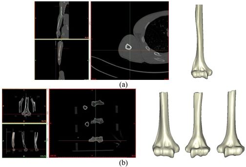
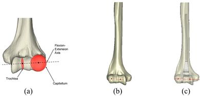
The Mimics software was used for the construction of elbow bones. Four different models of humerus bones were constructed with varied sizes. One of the models was constructed from CT data with a resolution of 0.477 mm and a slice thickness of 0.7 mm. The other three models were constructed from CT data with a resolution of 0.625 mm and a slice thickness of 2.5 mm (Figure 3 ). The flexion-extension axis is oriented along a line through the anteroinferior aspect of the medial epicondyle (or the rotation center of the greater sigmoid notch) and projected center of the capitellum [16,17]. Figure 4 shows the determination of the flexion-extension axis on the constructed bone in Mimics software. Thereafter, the modeled implant was inserted strategically into the humerus bones.
|
| Figure 3. Constructed humerus bones from CT data. (a) Resolution of 0.477 mm. (b) Resolution of 0.625 mm |
|
| Figure 4. (a) The anatomic flexion-extension axis of distal humerus. (b) Flexion-extension axis. (c) transparent view of the implanted bones |
2.3 Modeling of surgical guide template
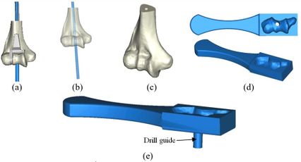
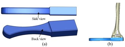
A rectangular mold was developed as a drill guide template using Mimics software. Then, the surgical guide was fitted on the first implanted humerus bone (Figure 5). The surgical guide needs to accurately seat on the distal of the humerus bone. The humerus bone was cut for further realization of the method. The modeled implant was inserted into the humerus bone based on the flexion-extension axis. A hole was made based on the position of the implant stem in the bone. In order to do it, a bar (with a similar dimension to the implant stem) was precisely fitted on the stem of the implant stem (Figure 6). A hole created by the bar had a diameter of 5 mm. The surgical guide was designed based on the shape of the distal region. Then, a hole was made in the surgical guide based on the direction and position of the implant stem. Finally, to lead the drill in the right direction, a drill guide was designed based on the position and direction of the hole in the bone. The same procedure was performed on all humerus bones.
|
| Figure 5. (a) Modeled surgical guide. (b) Surgical guide fitted on the implanted bone |
2.4 Fabrication and metal sleeve preparation
Surgical guides and humerus bones were fabricated, using a 3D printer (Dimension elite, Stratasys, USA) technique (Figure 7). CAD files of humerus bones and the surgical guides, in STL format, were transferred to the 3D printer. A metallic sleeve was fixed inside the hole of the surgical guide that guides the drill to accommodate the passage of the drill precisely. A standard tube (Ekinciler Iron and Steel IND. INC, Istanbul, Turkey) with an internal diameter of 5.2 mm and an external diameter of 5.5 mm was provided for the metal sleeve. As the internal diameter of the sleeve should be 0.2 mm bigger than the diameter of the drill [29,30], a sleeve with a 5.2 mm internal diameter was used for a 5 mm surgical drill. The tube was cut into 5 mm length, using a saw. A super glue (UHU, UHU GmbH & Co. KG, Germany) was used to fix the metallic sleeve firmly inside the drill guide.

|
| Figure 7. (a) Fabricated surgical guide. (b) Metalic standard tube. (c) Fabricated surgical guide |
The position of the holes was measured in the Mimics software to validate the accuracy of the method. A power drill with a 5.0 diameter drill bit was used to make a hole in the bones (Figure 8). A F-clamp was used to fix the bones, then, the surgical guides were set on the bones precisely. Since the surgical guides were designed based on the shape of the bones, they were mounted on the bone smoothly and without any movement to the sides. Consequently, the bones were drilled using a drill machine. A caliper was used to measure the position of the planned and achieved holes in the bones. The positions of the tip and base of the bone are as follows:
- -Base-distance: Diversity in distances at the implanted bone shoulder in the direction of medial/lateral and posterior/anterior.
- -Tip-distance: Diversity in distances at the implanted bone apex in the direction of medial/lateral and posterior/anterior.

|
| Figure 8. The sequence of making a hole in bones using surgical guide template |
3. Results
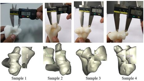
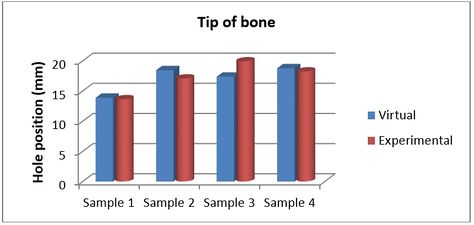
Figures 9 and 10 show the achieved and planned positions of the hole at the bone apex in the medial/lateral direction. On one side, the Mimics software package was used to make a hole and on the other side, similar holes were made experimentally, using the surgical guide template. Virtually, the positions of the holes were measured at 13.88 mm, 18.45 mm, 17.37 mm, and 18.77 for Sample 1, 2, 3, and 4 in the medial/lateral direction, respectively. Experimentally, the positions of the holes were measured at 13.63 mm, 18.07 mm, 16.91 mm, and 18.24 for Samples 1, 2, 3, and 4, respectively, in the same direction.
|
| Figure 9. Position of planned and achieved holes at the tip of bone in medial/lateral direction |
|
| Figure 10. Position of planned and achieved holes at the bone apex in the medial/lateral direction |
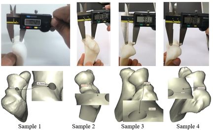
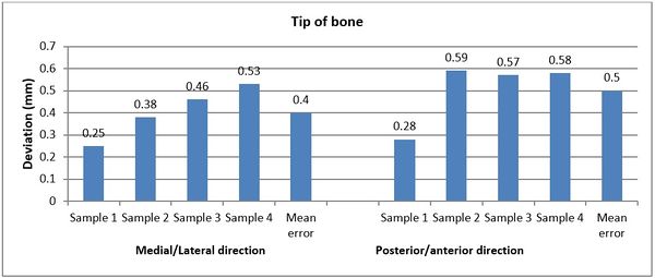
Figures 11 and 12 present the achieved and planned positions of the hole at the bone apex in the posterior/anterior direction. Virtually, the positions of the holes were measured at 10.70 mm (Sample 1), 14.91 mm (Sample 2), 9.88 mm (Sample 3), and 14.04 (Sample 4) in the posterior/anterior direction. Experimentally, the positions of the holes were measured at 10.42 mm, 14.32 mm, 9.31 mm, and 13.46 for Sample 1, 2, 3, and 4 respectively. The deviations (errors) between the achieved and planned holes at the bone apex were seen at 0.28 mm, 0.59 mm, 0.57 mm, and 0.58 mm for samples 1, 2, 3, and 4 respectively in the posterior/anterior direction. However, the deviations in the medial/lateral direction were 0.25 mm, 0.38 mm, 0.46 mm, and 0.53 mm for samples 1, 2, 3, and 4 respectively (Figure 13).
|
| Figure 11. Planned and achieved holes at the tip of bone in posterior/anterior direction |

|
| Figure 12. Position of planned and achieved hole at the bone apex in the posterior/anterior |
|
| Figure 13. Deviations (errors) between planned and achieved holes at the bone apex in medial/lateral and posterior/anterior directions |
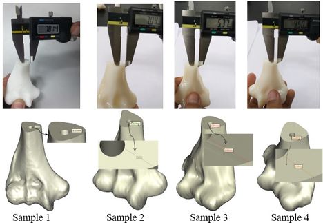
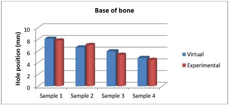
The achieved and planned positions of the holes at the base of the bone in the medial/lateral direction are shown in Figures 14 and 15. The positions of the holes (experimentally) were measured at 7.81 mm, 7.04 mm, 5.37 mm, and 4.50 mm for Samples 1, 2, 3, and 4 respectively. Virtually, the positions of the holes for samples 1, 2, 3, and 4 were measured at 8.10 mm, 6.62 mm, 5.95 mm, and 4.82 mm in the same direction, respectively.
|
| Figure 14. Planned and achieved hole at the base of the bone in the medial/lateral direction |
|
| Figure 15. Position of planned and achieved holes at the base of the bone in the medial/lateral direction |
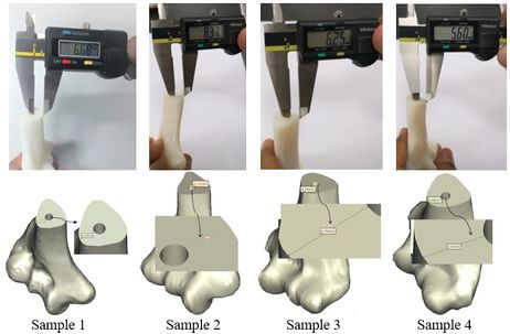
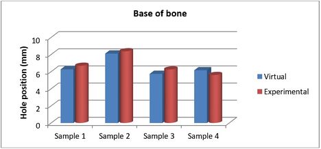
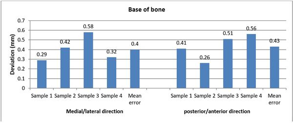
The achieved and planned positions of the holes at the base of the bone in the posterior/anterior direction are shown in Figures 16 and 17. Virtually, the positions of the holes for Samples 1, 2, 3, and 4 were measured at 6.27 mm, 8.11 mm, 5.74 mm, and 6.16 mm, respectively. Experimentally, the positions of the holes were measured at 6.68 mm, 8.37 mm, 6.25 mm, and 5.60 mm for Samples 1, 2, 3, and 4, respectively. In the posterior/anterior direction, the deviations at the base of bones were 0.41 mm (Sample 1), 0.26 mm (Sample 2), 0.51 mm (Sample 3), and 0.56 mm (Sample 4) (Figure 18). However, the deviations were 0.29 mm, 0.42 mm, 0.58 mm, and 0.32 mm for Samples 1, 2, 3, and 4 respectively, in the medial/lateral direction.
|
| Figure 16. Planned and achieved holes at the base of the bone in the posterior/anterior direction |
|
| Figure 17. Position of planned and achieved holes at the base of the bone in the posterior/anterior direction |
|
| Figure 18. The deviation between planned and achieved holes at the base of the bone in medial/lateral and posterior/anterior directions |
4. Discussion
There are no good results for the elbow joint replacements when compared with the knee and hip replacements. Early loosening of joint arthroplasties, instability, limited range of motion, and dislocation in patients with articulated fixators, subluxation, and excessive polyethylene wear are the results of incorrect selection of the flexion-extension axis during surgery [1,2,31]. While various mechanisms of implant loosening, as the main causes of elbow implant failure, have been recommended, implant malpositioning might probably be the important underlying reason. This axis is related to the alignment tools during surgery. After surgery, the kinematics of the elbow axis is altered; hence, the muscle moment arms and the arm motion pattern also change. This enhances the load at the articular bearing, which causes loosening and implant wear [32,33]. Proper selection of the flexion-extension axis results in accurate implant placement. A very tiny error on the distal humerus width (only a few millimeters in the axis endpoints selection) can change several degrees in orientation. Previous studies had investigated the importance of implant alignment with respect to load transfer and kinematics [34,35]. The position of the stem in the canal has a vital role in the survivability of the implant. Optimum implant positioning and technique used for its alignment are vital parameters to improve clinical results. A study showed that a gradual increase in prosthetic survival is possible through the development of surgical techniques [36]. The orthopedic CAD/CAM surgery is becoming more popular with a concentration on the spine, hip, and knee. However, the elbow joint suffers from a lack of knowledge [37,38]. Hence, in this study, a technique was used to model the surgical guide template to identify the flexion-extension axis, position, and orientation of stem inside the humerus canal. The used technique permitted the conversion of a radiographic guide to a surgical guide template.
Visual cues and jigs are the current surgical techniques used to estimate the elbow’s flexion-extension axis for TEA [9,16,17]. The surgeons extend this line (during surgery) visually to make an intersection between the lateral and medial surfaces of the distal humerus, close to the epicondyles. Morrey et al. (2000) presented this technique in an external dynamic joint distractor [11]. However, Brownhill et al. (2006) proved that this technique can lead to prominent errors for the flexion-extension axis. Nevertheless, the use of cues and jigs may lead to flexion-extension axis identification errors upwards of 10° [19,39].
Recently, CAD/CAM has been employed to enhance the precision of determining the elbow’s flexion-extension axis. The appropriate implant position and mechanical limb alignment could be more accurately produced with the computer-assisted system compared with the conventional and traditional techniques. The establishment of a preoperative plan, as well as diagnosis, could be more reliable when the 3D medical image of the anatomy was obtained. Surgeons are allowed to use navigated guidance by registering the preoperative data to the patient while referencing the benchmarks on the preoperative plan that is not accessible in the surgical exposure. This can assist the surgeons to create a treatment plan prior to implant placement [40,41]. The recent progress in medical imaging and computer field aids surgeons to use the newest equipment, such as a CT scanner. The most distinguished benefit of the CT scan method is the higher level of precision than other methods. Its proficiency has been mentioned in previous studies [42]. There are various applications of CAD in biomedical engineering such as tissue engineering, implant design, medical device design, and preoperative simulations.
In this study, 3D surgical site reconstruction was achieved, using CT data. This permitted the fabrication of a surgical guide using RP and the virtual implant planning via restorative considerations. The flexion-extension line was expanded to intersect the lateral and medial surfaces of the distal humerus, using Materialise Mimics software package. The usual method was used to match the planned and achieved positions by measuring the transfer precision of the computer-based 3D plan. The results showed that the deviations between the achieved and planned holes at the bone apex were 0.28 mm, 0.59 mm, 0.57 mm, and 0.58 mm for samples 1, 2, 3, and 4 respectively in the posterior/anterior direction. However, the deviations in the medial/lateral direction were 0.25 mm, 0.38 mm, 0.46 mm, and 0.53 mm for Sample 1, 2, 3, and 4, respectively. At the base of the bone, the samples 1, 2, 3, and 4 were experienced deviations at 0.41 mm, 0.26 mm, 0.51 mm, and 0.56 mm respectively in the posterior/anterior direction. Furthermore, the deviations were 0.29 mm, 0.42 mm, 0.58 mm, and 0.32 mm for Sample 1, 2, 3, and 4, respectively, in the medial/lateral direction.
Brownhill et al. applied real-time computer feedback to position the humeral component in 5 cadaveric extremities. The overall positioning errors were 1.7±2.1 mm (superior), 1.5±1.2 mm (anterior), and 1.2±1.4 mm (medical) relative to the native articulation [38]. McDoland et al. (2007) evaluated the conventional paired-point registration method against the surface-based registration technique. The conventional registration method showed an alignment error at 1.9 +/- 1.0 mm, whereas the surface-based registration method presented an error at 0.8 +/- 0.3 mm [43]. In another study, McDoland et al. (2011) validated the precision of a computer-aided implant placement technique. The study was carried out for both the modified and regular humeral components. The average alignment error of the regular stem was 1.9 ± 1.1 mm, while the reduced stem showed an averaged error of 1.3 ± 0.5 mm in translation [44]. Furthermore, McDoland et al. (2010) investigated the humeral component implant alignment, using a CT-based preoperative plan measured to landmarks on the distal humerus. The alignment was carried out under two categories, namely intact humerus and humerus without articular landmarks. The navigated implant alignment was 1.2 +/- 0.3 mm for the intact bone and 1.1 +/- 0.5 mm for the bone loss. For the non-navigated alignment method, the alignment was 3.0 +/- 1.6 mm for the bone loss category and 3.1 +/- 1.3 mm for the intact scenario [45]. Deluce et al. (2018) used an intra-operative surface-based registration technique for a radial head implant. The positioning errors were 0.8 ± 0.5 in the medial-lateral direction and 0.8 ± 0.6 in the anterior-posterior direction. A registration error of less than 1.0 mm was also observed [46]. In this study, the deviation (error) between the achieved and planned positions was less than 0.50 mm. The value was less than the reported implant placement, using a computer-aided surgical system. The introduced method prepared a radiographic guide that can be converted into a surgical guide template. In addition to this, the use of multiple guides is not necessary for the drilling sequence. This surgical guide template can be used in a wide range of implant systems.
Generally, drastic destruction of the elbow happens in the replacement of an elbow joint, which is especially visible in patients with RA. The more proximal location of an implant in the affected elbows is a result of the deficient distal humerus bone stock. The visual assessment of anatomic landmarks is more complicated in elbows with severe bone loss, such as fractures, tumors, and end-stage RA. This causes more error in the estimation of the flexion-extension axis and eventually, the alignment targets and precise identification of landmarks tend to vary under non-ideal conditions encountered during surgery. Errors in orienting landmarks can increase throughout the operation when the cutting guides or jigs are referred from these anatomic reference points. However, in the current study, CT data were used for the estimation of the flexion-extension axis before surgery. The flexion-extension axis was determined after carefully surveying the bone. Therefore, proper alignment in the introduced technique is more likely to happen than when jig and cues are used during surgery.
In the present study, a drill guide was considered for the surgical guide. A metallic guide was relatively matched to the drill and implant diameter to improve the precision of the surgical guide. The main body of the surgical guide was suitably fitted on the bone to ensure the stability of the template during surgery. Holes were made based on the planned position of the stem. A stainless-steel tube was truly fixed within the hole to protect the ABS plastic against the sharpness of the drill. When performing surgery, a tube size that is 0.2 mm wider than the drill can be used to prevent the drill from contacting the stainless steel tube [47]. In this study, the height of the drill guide was not evaluated as it is not a pivotal parameter for the precision of implant placement [21]. Surgical guides without accurate drill guides are used as a proximate guide only. Therefore, the implant may be placed in a different position compared to the planned position.
Several studies have investigated the precision of the CAS method. Van Steenberghe et al. (2002) investigated the CAD/CAM surgical guide accuracy in cadavers, whereas Vrielinck et al. (2003) carried out the same study on human subjects [48, 49]. Gschwend et al. (2000) used a template to insert a guiding Steinmann pin inside the humerus bone to make a hole preoperatively [50], while Donald et al. evaluated a different way of humeral stem positioning. The computer-assisted technique for TEA was proven to improve implant alignment compared to the conventional methods [18]. Stacpoole et al. studied the effect of radial head implant position on joint kinematics and tracking using a computer-aided implant placement procedure [51]. Recently, surgeons have attained a modified tool for the alignment of the hip, shoulder, and knee. Although it demonstrated much promise, there has been quite limited application of this technology to the elbow, and has, thus far, been limited to laboratory studies only. Since elbow replacements may not be used by most surgeons, the navigation system may be preferred over higher-volume arthroplasties such as the hip and knee. This may result in a decrease in wear for linked implants and reduced instability for unlinked devices. However, clinical studies should confirm these hypotheses.
Clinical studies have shown a higher rate of loosening for the humeral component than the ulnar component. Excessive loading of the implant stem is caused by malpositioning of the humeral component [52,53]. The humeral stem restricts modularity in the orientation and situation of the implant articulation axis. Previous studies showed that the kinematics change of elbow replacement was due to the malrotation of the humeral component. This malposition would cause elbow wear, laxity, and loosening [33,54]. Consequently, in this study, the surgical guide was designed only for the humeral stem.
To the authors’ knowledge, this study is the first to use such a technique for humeral implant positioning. Even though the errors in implant positioning were greater than 1 mm, the results of this study showed improvement in terms of surgical errors. The introduced method possesses a lot of advantages for TEA. Firstly, the surgeon is able to select the size and placement of the hole based on the unique morphology of the humerus bone before surgery. The second advantage is the preoperatively prepared drill guide can be used to make the hole in proper direction and angulation. Thirdly, it does not require complex equipment in the operating room. Last but not least, it is easy to make and use. Furthermore, it is possible to use different drill sizes and it does need to be adjusted by a jig. This study recommends the use of a 3D planned template as a surgical guide as it is a reliable technique for implant placement during surgery.
Acknowledgement
We acknowledge Global College of Engineering and Technology (Oman) for supporting this study.
References
[1] Lee B.P., Adams R.A., Morrey B.F. Polyethylene wear after total elbow arthroplasty. J. Bone Joint Surg. Am., 87:1080-1087, 2005.
[2] Wright T.W., Hastings H. Total elbow arthroplasty failure due to overuse, C-ring failure, and/or bushing wear. J. Shoulder Elbow Surg., 14:65-72, 2005.
[3] Voloshin I., Schippert D.W., Kakar S., Kaye E.K., Morrey B.F. Complications of total elbow replacement: A systematic review. J. Shoulder Elbow Surg., 20:158-168, 2011.
[4] Sotelo J.S. Total elbow arthroplasty. J. Open Orthop., 5:115-123, 2011.
[5] Trigg S.D. Total elbow arthroplasty: current concepts. Florida, 2006.
[6] Heidari M., Harun M.N., Syahrom A. Influence of polyethylene thickness on axis pin in linked elbow implant. Advanced Mater. Res., 845:194-198, 2014.
[7] Ramsey M.L. Linked total elbow arthroplasty. Operative Techniques in Orthop., 20(1):48-57, 2010.
[8] Chafik D., O’Driscoll S., King G.W., Yamaguchi K. Total elbow arthroplasty-convertible. Operative Techniques in Orthop. 20:58-67, 2010.
[9] Ren K., Dusad A., Zhang Y., Wang D. Therapeutic intervention for wear debris- induced aseptic implant loosening. Acta Pharmaceutica Sinica B., 30(2):76- 85, 2013.
[10] Van der Lugt J.C.T., Valstar E.R., Witvoet-Braa S.W., Nelissen R.G.H. Migration of the humeral component of the Souter-Strathclyde elbow prosthesis. Bone Joint Surg. Br., 92(2):235-241, 2010.
[11] Morrey B.F., Hotchkiss R.N. External fixators of the elbow: The elbow and its disorders. Philadelphia: Saunders, 457-467, 2000.
[12] Matziolis G., Krocker D., Weiss U., Tohtz S., Perka C. A prospective, randomized study of computer-assisted and conventional total knee arthroplasty. Three-dimensional evaluation of implant alignment and rotation. J. Bone Joint Surg. Am., 89:236-243, 2007
[13] McDonald C.P., Peters T.M., Johnson J.A., King G.J.W. Stem abutment affects alignment of the humeral component in computer-assisted elbow arthroplasty. J. Shoulder Elbow Surg., 20(6):891-898, 2011.
[14] Molli R.G., Anderson K.C., Buehler K.C., Markel D.C. Computer-assisted navigation software advancements improve the accuracy of total knee arthroplasty. J. Arthroplasty, 26(3):432-438, 2011.
[15] Brownhill J.R., Pollock J.W., Ferreira L.M., Johnson J.A., King G.J.W. The effect of implant malalignment on joint loading in total elbow arthroplasty: an in vitro study. J. Shoulder Elbow Surg., 21:1032-1038. 2012.
[16] An K.N., Morrey B.F. Biomechanics of the elbow. In Morrey B.F. (editor), The elbow and its disorders, WB Saunders, Philadelphia, 2000.
[17] Bottlang M., O’Rourke M.R., Madey S.M., Steyers C.M., Marsh J.L., Brown T.D. Radiographic determinants of the elbow rotation axis: experimental identification and quantitative validation. J. Orthop. Res., 18:821-828, 2000.
[18] McDonald C.P., Johnson J.A., Peters T.M., King G.J. Image-based navigation improves the positioning of the humeral component in total elbow arthroplasty. J. Shoulder Elbow Surg., 19:533-543, 2010.
[19] Brownhill J.R., Furukawa K., Faber K.J., Johnson J.A., King G.J. Surgeon accuracy in the selection of the flexion-extension axis of the elbow: an in vitro study. J Shoulder Elbow Surg., 15:451-456, 2006.
[20] Turbush S.K., Turkyilmazn I. Accuracy of three different types of stereolithographic surgical guide in implant placement: An in vitro study. J. Prosthetic Dent., 108:181-188, 2012.
[21] Park C., Raigrodski A.J., Rosen J., Spiekerman C., London R.M. Accuracy of implant placement using precision surgical guides with varying occlusogingival heights: An in vitrostudy. J. Prosthet Dent., 101:372-381, 2009.
[22] Jung K.A., Kim S.J., Lee S.C., Hwang S.H., Ahn K.N. Accuracy of implantation during computer-assisted minimally invasive Oxford unicompartmental knee arthroplasty A comparison with a conventional instrumented technique. The Knee., 17:387-391, 2010.
[23] Brownhill J.R., Mozzon J.B., Ferreira L.M., Johnson J.A., King G.J.W. Morphologic analysis of the proximal ulna with special interest in elbow implant sizing and alignment. J. Shoulder Elbow Surg., 18:27-32, 2009.
[24] Heidari M., Harun M.N., Kadir M.R.A., Kashani J., Syahrom A. Effect of humeral stem shape on displacement in elbow implant. Applied Mechanics and Mater, 393:467-471, 2013.
[25] Shahbazian M., Jacobs R., Wyatt J., Willems G., Pattijn V., Dhoore E., Van Lierde C., Vinckier F. Accuracy and surgical feasibility of a CBCT-based stereolithographic surgical guide aiding autotransplantation of teeth in vitro validation. J. Oral Rehabilitation, 37(11):854-859, 2010.
[26] Han B.K., Lindberg J., Grant K., Schwartz R.S., Lesser J.R. Accuracy and safety of high pitch computed tomography imaging in young children with complex congenital heart disease. Am. J. Cardiology., 107(10):1541-1546, 2011.
[27] Katatny E.I., Masood S.H., Morsi Y.S. Error analysis of FDM fabricated medical replicas. Rapid Prototyp. J., 16(1):36-43, 2010.
[28] Ozan O., Turkyilmaz I., Ersoy A.E., McGlumpby E.A., Rosenstiel S.F. Clinical accuracy of 3 different types of computed tomography-derived stereolithographic surgical guides in implant placement. J. Oral Maxillofacial Surg., 67(2):394-401, 2009.
[29] Kashani J., Kadir M.R.A., Arabshahi Z. A surgical drill guide for pedicle screw placement. International Conference on Biomedical Engineering, Penang, February 27-28, 2012.
[30] Atsu S.S. A surgical guide for dental implant placement in edentulous posterior regions. J. Prosthes. Dent., 96(2):129-133, 2006.
[31] Heidari M., Kadir M.R.A., Kashani J., Fallahiarezoodar A., Alizadeh M., Robson N., Kamarul T., Harun M.N. Influences of rheumatoid arthritis on elbow: A finite element analysis. Journal of Advanced Science Letters., 19(11):3219-3222, 2013.
[32] Bennett J.B., Mehlhoff T.L. Total elbow arthroplasty: surgical technique. J. Hand Surg., 34:933–939, 2009.
[33] O’Driscoll S.W., King G.J. Treatment of instability after total elbow arthroplasty. Orthopedic Clinics of North Am., 32:679-695, 2001.
[34] Gramstad G.D., King G.J., O’Driscoll S.W., Yamaguchi K. Elbow arthroplasty using a convertible implant. Tech Hand Up Extrem Surg., 9:153-163, 2005.
[35] Schuind F., O’Driscoll S., Korinek S., An K.N., Morrey B.F. Loose-hinge total elbow arthroplasty. An experimental study of the effects of implant alignment on three-dimensional elbow kinematics. J. Arthroplasty, 10:670-678, 1995.
[36] Ericson A., Stark A., Arndt A. Variation in the position of the elbow flexion axis after total joint replacement with three different prostheses. J. Shoulder Elbow Surg, 17:760-767, 2008.
[37] Holly L.T., Bloch O., Johnson J.P. Evaluation of registration techniques for spinal image guidance. J. Neurosurg. Spine., 4:323-328, 2006.
[38] Brownhill J.R., McDonald C.P., Ferreira L.M., Pollock J.W., Johnson J.A., King J.W. Kinematics and laxity of a linked total elbow arthroplasty following computer navigated implant positioning. Computer Aided Surgery, 17(5):249–258, 2012.
[39] Brownhill J.R., Furukawa K., Faber K.J., Johnson J.A., King G.J. Surgeon accuracy in the selection of the flexion-extension axis of the elbow: An in vitro study. J. Shoulder Elbow Surg, 15:451-456, 2006.
[40] McDonald C.P., Peters T.M., King G.J.W., Johnson J.A. Computer assisted surgery of the distal humerus can employ contralateral images for pre-operative planning, registration, and surgical intervention. J. Shoulder Elbow Surg., 18:469-477, 2009.
[41] Jung K.A., Kim S.J., Lee S.C., Hwan S.H., Ahn N.K. Accuracy of implantation during computer-assisted minimally invasive Oxford unicompartmental knee arthroplasty: a comparison with a conventional instrumented technique. J. Knee, 17:387-391, 2010.
[42] Tohnak S., Mehnert A.J., Mahoney M., Crozier S. Synthesizing dental radiographs for human identification. J. Dent. Res., 86:1057-1062, 2007.
[43] McDonald C.P., Brownhill J., King G.J.W., Peters T. A comparison of registration techniques for computer- and image-assisted elbow surgery. Computer Aided Surgery, 12(4):208-214, 2007.
[44] McDonald C.P., Peters T.M., Johnson J.A., King G.J. Stem abutment affects alignment of the humeral component in computer-assisted elbow arthroplasty. J. Shoulder Elbow Surg., 20(6):891-898, 2011.
[45] McDonald C.P., Johnson J.A., Peters T.M., King G.J. Image-based navigation improves the positioning of the humeral component in total elbow arthroplasty. J Shoulder Elbow Surg., 19(4):533-543, 2010.
[46] Deluc S.R., Shannon H., Lalone E.A., Athwal G.S., Ferreira L.M., King G.J.W., Johnson J.A. A computer and image-assisted guidance system for radial head arthroplasty. Computer Methods in Biomechanics and Biomedical Engineering: Imaging & Visualization, 6(2):204-210, 2018.
[47] Frederiksen N.L. Diagnostic imaging in dental implantology. Oral Surg. Oral Med. Oral Pathol. Oral Radiol. Endod., 80(5):540-554, 1995.
[48] Van S.D., Naert I., Andersson M., Brajnovic I., Van C.J., Suetens P. A custom template and definitive prosthesis allowing immediate implant oading in the maxilla: a clinical report. Int. J. Oral Maxillofac Implants., 17:663-670, 2002.
[49] Vrielinck L., Politis C., Schepers S., Pauwels M., Naert I. Image-based planning and clinical validation of zygoma and pterygoid implant placement in patients with severe bone atrophy using customized drill guides. Preliminary results from a prospective clinical follow-up study. Int. J. Oral Maxillofac Surg., 32(1):7-14, 2003.
[50] Gschwend N. Present state of art in elbow arthroplasty. Acta Orthopædica Belgica, 68(2):100-117, 2002.
[51] Stacpoole R.A., Ferreira L.M., King G.J.W., Johnson J.A. Development of computer-assisted radial head replacement. International Conference on Medical Image Computing and Computer-Assisted Intervention, MICCAI 2003: Medical Image Computing and Computer-Assisted Intervention, 199-206, 2003.
[52] Hildebrand K.A., Patterson S.D., Regan W.D., MacDermid J.C., King G.J. Functional outcome of semiconstrained total elbow arthroplasty. J. Bone Joint Surg. Am., 82:379-1386, 2000.
[53] Kamineni S., Morrey B.F. Proximal ulnar reconstruction with strut allograft in revision total elbow arthroplasty. J. Bone Joint Surg. Am., 86:1223-1229, 2004.
[54] King G.J., Itoi E., Niebur G.L., Morrey B.F., An K.N. Motion and laxity of the capitellocondylar total elbow prosthesis. J. Bone Joint Surg. Am., 76(7):1000-1008, 1994.
Document information
Published on 12/01/21
Accepted on 11/10/20
Submitted on 21/07/20
Volume 37, Issue 1, 2021
DOI: 10.23967/j.rimni.2020.10.006
Licence: CC BY-NC-SA license
Share this document
Keywords
claim authorship
Are you one of the authors of this document?
