1 Introduction
Composite materials are a reliable and appropriate alternative to metal structures and elements. These materials can reduce costs and weight by maintaining high values of strength and security. Through the use of different matrices and reinforcements it is possible to develop new materials capable of adapting to the needs raised at each moment. Nowadays these types of material are used in all industrial areas. From highly technological aerospace industry, with the clear example of the Boeing 787 Dreamliner which structure consists of more than 50% composite materials, to less technological shoe industry.
Focusing on the aerospace industry, epoxy resin is the most used matrix. However, different reinforcements are used depending on the application, highlighting carbon, glass, kevlar and boron fibers [1]. These materials are located in different sections of the aircraft as primary structure component (its integrity is critical for the aircraft), control components (as ailerons or spoilers), external components (as fairings or radomes) and internal components (as floors or doors). Conventional carbon fiber reinforced polymer matrix composites are prone to suffer from stress concentration, being necessary the development of new composite materials such as MMC and PMC with more balanced properties by fiber selection [2]. Yadav et al. [3] review the use of various polymer nano-composites in addition to epoxy composites based on carbon fillers for antistatic application in aircraft. Barile et al. [4] develop two different composites by combining the same fibers with two types of resins and two manufacturing processes. They verify that elastic properties are affected by the type of resin while the compressive behavior is differently affected by the manufacturing process.
Nowadays there are different ways to manufacture composite materials pieces: hand lay-up, spray lay-up, resin transfer molding, compression molding, injection molding, vacuum assisted method, autoclave processing, pultrusion and filament winding [5]. In this project it was decided to work with the resin and the carbon fibers separately, beginning the manufacturing of the node from A-Stage, instead of using prepregs (B-Stage). Prepregs allow a greater ease in the manufacture of complex pieces of CFRP (carbon fiber reinforced polymer), however also have a number of very important limitations: early expiration, need to be stored in the freezer at low temperatures and especially the cost. By using the resin and the fibers separately from A-Stage costs could be reduced, materials were stored at room temperature in the lab and same resin and fibers could be used by the partners of this project. Once the starting point in the manufacturing of the node was decided, hand lay-up process to manufacture the node was selected.
In recent years, the use of adhesives in industrial processes has increased. This is possible due to the development of structural adhesives. Adhesives provide great advantages over other forms of join, being the most outstanding: creation of a continuous bond, corrosion prevention (sealed joint), stress distribution over a joint area, vibration reduction, invisibility of joints within assembly, minimization of an assembly mass, no substrate deformation and minimizations of components in an assembly [6].
Nowadays these materials are used in many industries [7] as diverse as aerospace, automotive, railway, marine, civil construction or electrical. Quan et al. [8] study aerospace-grade composite adhesive joints. By adding steel fibers in the adhesive layer both Mode I and Mode II fracture toughness are enhanced. Banea et al. [9] study multi-material adhesive joints for automotive industry, showing benefits as design flexibility and ability to join dissimilar and/or new materials. Huang et al. [10] propose a new waterproof seal layer using polyurethane adhesive to prevent water from infiltrating into the subgrade bed under the slab track of high-speed railway. Speth et al. [11] show greater use of adhesives and composite materials in the marine industry in recent years, finding a new design challenge in the use of bonded joints between composite and steel structures. A logical method for the design and certification of adhesively-bonded composite to steel joints for the marine industry is described. Adhesive joints are becoming increasingly important also in the civil industry, entailing several challenges related to the joint durability. Sousa et al. [12] study the effects of outdoor and hygrothermal ageing on the physical and mechanical properties of a structural epoxy adhesive for its use in civil engineering applications. Galvez et al. [13] study the effect of moisture and temperature in the mechanical and thermal properties of steel-CFRP adhesive joints using polyurethane adhesives for their application as reinforcement in structural engineering. New developments in adhesives with conductive capabilities make possible their use in electrical and electronic applications. Two examples are new graphene and carbon nanotube reinforced epoxy adhesives created by Han et al. [14]. This kind of adhesive show better mechanical and conductive properties than non-reinforced adhesives and are able to be used in electronic applications.
Current bus structures have great fatigue problems due to their rigidity, resulting in unwanted breaks at certain stress concentration nodes [15]. Nowadays the most used material in the manufacture of bus structures is the high strength steel, since it provides good mechanical properties at a reasonable price. Bus structures are formed by hollow rectangular cross sections beams joined to each other by welding. Main reasons given by the manufacturers for using welded joints are the cost, and the fact that welding is a fast and sturdy process. In the same way there are hardly any dimensional changes and it is not necessary to use filling material [16]. On the other hand, heat affected zones appear during the welding process, decreasing the joint strength [17]. Premature failures can appear due to corrosion, and dynamic loads can trigger a fatigue process that favors the appearance of cracks [18,19].
In order to avoid this problem, a new CFRP node has been designed and manufactured. Structural polyurethane adhesive has been used to join the node to two steel beams equal to those used in the bus structure. By mean of four-point flexural test, the capacity of the new prototype has been tested in comparison with the current welded steel nodes.
2 Experimental procedure
2.1 Materials
New node had been manufactured using carbon fiber reinforced polymer from A-Stage. Epoxy resin (SR 8500 – Sicomin Epoxy Systems – Châteauneuf-les-Martigues, France) with hardener (SD8601 – Sicomin Epoxy Systems – Châteauneuf-les-Martigues, France) was selected as matrix. Carbon fiber fabric (GG 600T – MEL Composites – Barcelona, Spain) was used as reinforcement. AISI 1012 carbon steel beams supplied by Carrocera Castrosua S.A. were used to manufacture complete node prototypes. These beams are exactly the same as those used by the bus manufacturer.
Different ductile adhesives were studied to evaluate the suitability of each of them for the raised problem. Single-component polyurethane adhesive (Sikatack® Drive) was selected due to its high strength and good behavior against environmentally adverse conditions. This adhesive is designed to join the windshield with the car body. It shows hyper-elastic behavior that makes it ideal for the application proposed in this work.
2.2 Surface treatment
Working with adhesives it is necessary to ensure cohesive failure. In this work two dissimilar materials (steel and CFRP) were bonded, which adds more difficulty to the process.
Two different surface treatments were carried out to guarantee the correct adhesion of the adhesive on both substrates. The treatment selected for the steel surface was: sanding with P180 sandpaper, solvent cleaning and Sika® Primer 204N. While the treatment for the CFRP surface was: solvent cleaning, APPT (6 mm of torch-specimen distance and 3 m/min of torch speed) and Sika® Primer 215.
2.3 Manufacturing process
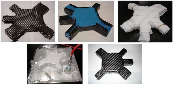
The complex design of the new CFRP node [15] results in many manufacturing problems. To solve this problem a PLA node was manufactured by 3D printing. This PLA node was used as a core for the final node of CFRP. In this way, the PLA core was covered layer by layer by hand lay-up process. Three layers of carbon fiber fabric were used in the manufacture of the node. Use a PLA core was a problem since the epoxy resin has poor compatibility with this material. Therefore, it was necessary to perform an atmospheric pressure plasma treatment on the surface of the core. The parameters used in the plasma were: 6 mm of torch-specimen distance and 3 m/min of torch speed. Activating the PLA surface, resin-core compatibility is increased. Figure 1 shows node manufacturing by hand lay-up process.
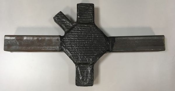
The final prototype was the result of joining the CFRP node by means of adhesives to the two steel beams (Figure 2). In previous works [15] the ideal adhesive configuration was calculated. CFRP node had been manufactured to allow a
clearance of 2 mm between steel beam and CFRP node surfaces. Therefore the adhesive thickness was 2 mm, occupying this empty space. In order to know the behavior of the whole set (CFRP node, adhesive and steel beams) three prototypes were manufactured and compared with the steel reference node.
2.4 Four-point flexural test
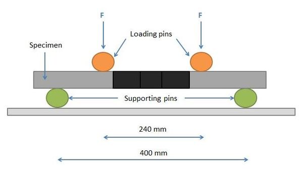
Four-point flexural tests were carried out in a universal testing machine with a load cell of 200 kN. Both new CFRP and steel prototypes were tested and compared. The behavior of the prototypes against deformation speed of 55 mm per minute was evaluated. Test configuration is shown in Figure 3, with loading pins distance of 240 mm and supporting pins distance of 400 mm. This test allows reproducing more adverse conditions than the service conditions of the bus. From the results of these tests, force-displacement curves, maximum force, displacement for maximum force, and absorbed energy are calculated.
3 Results
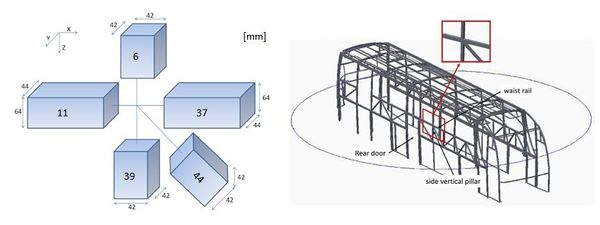
New node concept has already been introduced in previous works [15]. Figure 4 shows the current representation of the steel node and its location in the bus structure and Table 1 shows the efforts in the stress concentration nodes under operating conditions.
| Beam | Fx [kN] | Fy [kN] | Fz [kN] |
| 6 | -0.45 | -0.08 | -0.52 |
| 11 | 2.36 | -0.04 | 0.02 |
| 37 | 4.32 | 0.02 | 0.17 |
| 39 | -0.31 | 0.10 | -2.00 |
| 44 | 2.72 | -0.01 | 2.33 |
3.1 Four-point flexural test
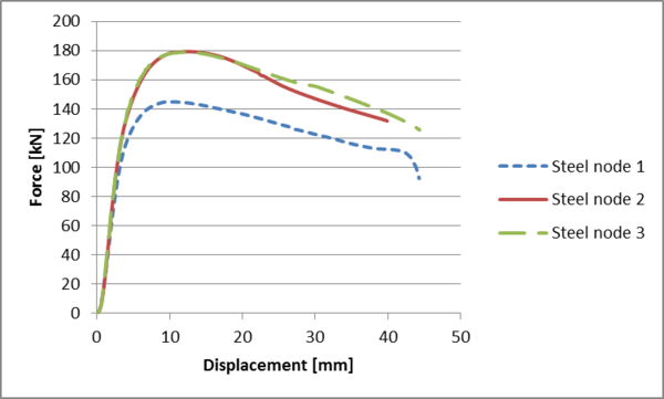
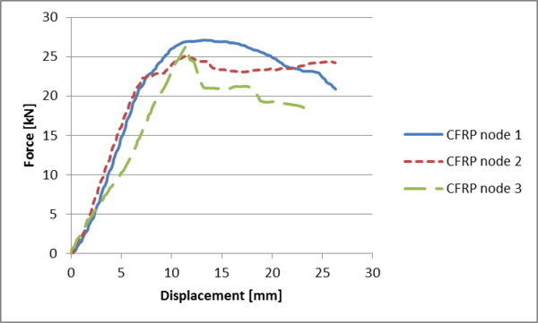
The steel node obtains a maximum force of 167.69±19.73 kN with a displacement of 11.29±1.49 mm, while CFRP node obtains 26.17±1.03 kN with a displacement of 13.32±3.18 mm. Figure 5 shows force-displacement curves of the steel nodes. It is observed that three curves are very similar, highlighting some difference in terms of maximum force value in steel node 1 curve. Figure 6 shows force-displacement curves of the CFRP nodes. Maximum force and displacement values are very similar even though the shapes of the curves are not very similar among them.
Figure 5. Force-displacement curves of the steel nodes.
Figure 6. Force-displacement curves of the CFRP nodes.
1.1 Absorbed energy
One of the main reasons to propose the substitution of welded by adhesive joints (besides the weight saving) is the possibility of giving a certain elasticity to the union, improving the fatigue behavior of the bus structure. The selected adhesive has hyper-elastic behavior and the new joint is less rigid than the current steel welding. At this point it is necessary to introduce the term of absorbed energy.
Energy corresponds to the area under the curve in the force-displacement graphs. Deformation energy (ED) and spring-back energy (ES) are calculated by integrating the area under the curve in the deformation and recovery phases respectively. Absorbed energy (EA) is calculated following:
EA = ED – ES (1)
Table 2 shows values of absorbed energy until reaching the maximum value of force in both steel and CFRP node. Logically, since the maximum value of force is greater in the steel node, the area under the curve and the absorbed energy up to that point are also greater.
| Steel node | CFRP node | |
| Deformation Energy (J) | 1416.85 ± 360.31 | 217.66 ± 91.85 |
| Spring-back Energy (J) | 552.14 ± 189.91 | 37.27 ± 33.15 |
| Absorbed Energy (J) | 864.72 ± 176.55 | 180.39 ± 97.57 |
Service conditions are much lower than maximum force values for both steel and CFRP node. Therefore, it is also convenient to carry out the study at low force values, more similar to the efforts to which the node is normally subjected. The absorbed energy has been calculated for a maximum force of 20 kN. Although this force value is still higher than the service conditions, it is closer to them than using the maximum value of force. And therefore it allows getting a clearer idea of the real behavior of the node under normal conditions. Table 3 shows energy values of both steel and CFRP nodes for a maximum force value of 20 kN.
| Steel node | CFRP node | |
| Deformation Energy (J) | 6.18 ± 1.04 | 67.46 ± 14.51 |
| Spring-back Energy (J) | 2.56 ± 0.89 | 37.27 ± 33.15 |
| Absorbed Energy (J) | 3.62±1.41 | 30.19 ± 24.63 |
CFRP node is capable of absorbing 10 times more energy (30.19 ± 24.63 J) than the steel node (3.62±1.41 J) under these conditions (more similar to the service conditions). This greater capacity for energy absorption is related to a better fatigue behavior of the joint, and therefore to a better assembly efficiency.
1.1 Failure analysis
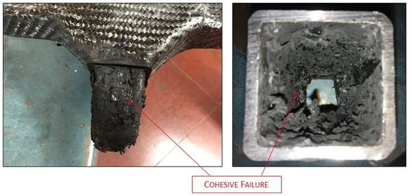
It is essential to thoroughly study the types of failure both in the adhesive and the CFRP node. Therefore, once four-point bending tests were completed, most affected areas of the new prototype were studied. Regarding the adhesive, cohesive failure has been obtained in all the tests as it is shown in Figure 7.
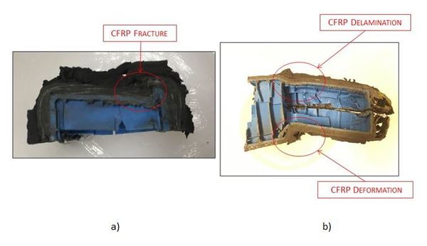
The node fails by the flanks of the arms. Failure modes found in the CFRP node are shown in Figure 8. Fracture is observed in Figure 8a, showing a clean break of the material. In Figure 8b delamination between fiber layers and material deformation are observed. Delamination is clear as separation of the fiber layers due to a failure of the matrix is observed. Regarding the deformation zone, the piece rotates without breaking or delaminating, but the transformation is permanent, reaching the plastic deformation zone of the material.
4 Conclusions
-The results show the capacity of the new CFRP node to be used in bus structures.
-Manufacturing method is very widespread so the CFRP node implementation would be viable on an industrial scale.
-Although the maximum strength results are lower in the CFRP node than in the steel node, results are sufficient to work in service conditions according to the requirements of the joint.
-The energy absorption capacity of the new CFRP node is greater for similar service conditions. Therefore, the use of new CFRP node together with adhesives improves the fatigue behavior of the assembly and makes it more efficient.
-The failure is cohesive in the adhesive joint. In the CFRP node, areas with material fracture, interlaminar delamination and plastic deformation are observed.
Acknowledgements
This research was supported by Ministerio de Economia y
Competitividad, Spain, under grants TRA2014-56471-C4-2-R. The authors gratefully acknowledge the collaboration of Castrosua S. A. for supplying the steel and Sika S.A.U. España for supplying the adhesives and the CFRP. IAAB (Alvaro Alonso Barba Technological Institute of Chemistry and Materials).
References
[1] D. Gay, S.V. Hoa, S.W. Tsai. Composite Materials, Design and Applications (2003), CRC Press LLC Boca Raton, ISBN 1-58716-084-6.
[2] X. Zhang, Y. Chen, J. Hu, Prog Aerosp Sci 97, pp. 22-34 (2018).
[3] R. Yadav, M. Tirumali, X. Wang, M. Naebe, B. Kandasubramanian, Def Technol (2019). https://doi.org/10.1016/j.dt.2019.04.008.
[4] C. Barile, C. Casavola, F. De Cillis, Compos Part B-Eng 162, pp. 122-128 (2019).
[5] K. Balasubramanian, M.T.H. Sultan, N. Rajeswari, Manufacturing techniques ocomposites for aerospace applications. In: Sustainable Composites for Aerospace Applications. M. Jawaid and M. Thariq editors. pp. 55-67. Woodhead Publishing. 2018. ISBN: 978-0-08-102131-6.
[6] K. Martinsen, S.J. Hu, B.E. Carlson, CIRP Ann-Manuf Techn 64, pp. 679-699 (2015).
[7] L.F.M. da Silva, A. Öchsner, R. Adams eds. Handbook of Adhesion Technology (2011), pp. 1101-1347, Springer-Verlag Berlin Heidelberg, ISBN 978-3-642-01168-9.
[8] D. Quan, J. L. Urdániz, C. Rouge, A. Ivanković, Compos Struct 198, pp. 11-18 (2018).
[9] M.D. Banea, M. Rosioara, R.J.C. Carbas, L.F.M. da Silva, Compos Part B-Eng 151, pp. 71-77 (2018).
[10] J. Huang, Q. Su, Y. Cheng, B. Liu, T. Liu, Constr Build Mater 208, pp. 710-722 (2019).
[11] D.R. Speth, Y.P. Yang, G.W. Ritter, Int J Adhes Adhes 30, pp. 55-62 (2010).
[12] J.M. Sousa, J.R. Correia, S. Cabral-Fonseca, Constr Build Mater 161, pp. 618-633 (2018).
[13] P. Galvez, J. Abenojar, M.A. Martinez, Compos Part B-Eng 165, pp. 1-9 (2019).
[14] S. Han, Q. Meng, S. Araby, T. Liu, M. Demiral, Compos Part A-Appl S 120, pp. 116-126 (2019).
[15] P. Galvez, A. Quesada, M.A. Martinez, J. Abenojar, M.J.L. Boada, V. Diaz, Compos Part B-Eng 129, pp. 41-46 (2017).
[16] Dost I, Khan SA, Aziz M, Int J Adv Eng Technol 5(1), pp. 259-268 (2012).
[17] Sakiyama T, Murayama G, Naito Y, Saita K, Miyazaki Y, Oikawa H, Nose T, Nippon Steel Tech Rep 103, pp. 91-98 (2013).
[18] Branco CM, Ferreira JA, Proceedings of the european conference on fracture ECF5, pp. 643-658 (1984).
[19] Perez JA, Badea F, Arribas D, Procedia - Soc Behav Sci 160, pp. 440-448 (2014). doi.org/10.1016/j.sbspro.2014.12.156.
Document information
Published on 29/06/22
Accepted on 29/06/22
Submitted on 29/06/22
Volume 04 - Comunicaciones Matcomp19 (2020), Issue Núm. 2 - Procesos de Fabricación y Técnicas de Unión, 2022
DOI: 10.23967/r.matcomp.2022.06.053
Licence: Other
Share this document
claim authorship
Are you one of the authors of this document?
