Abstract
The use of tensegrity structures in robotics has been studied in recent years thanks to their properties of light weight, efficient distribution of forces and the possibility of applying control methods for the active shape reconfiguration, with crawling and rolling as examples. The structural composition of tensegrities, particularly the use of tensile elements, results in the presence of infinitesimal mechanisms. These affine motions have been considered for the development of control strategies that follow the manifold of stable positions described by these mechanisms. However, in robotic applications, the presence of rigid body motions can cause undesired effects, such as tensegrity structures flipping over. The form finding methods available in literature consider only the statics of tensegrities and most dynamic models work assume free-standing structures, while few consider fixed structures but do not deepen into the process of removing the rigid body motions.
In this paper, the formulation of the equilibrium equations of tensegrity structures is reviewed, to describe the presence of the affine motions in the vector spaces of the equilibrium matrix. A simplified method for removing rigid body motions from the equilibrium equations is detailed, and the effect on the set of affine motions is explained. To verify the validity of this process, two numerical examples are given, including a single unit and a two stage tensegrity structures.
Keywords: Tensegrity, affine motions, rigid body, fixed nodes
1. Introduction
Next to the dilemma of who is the real inventor of the tensegrity principle, the definition of what is a tensegrity structure, and what is not, has been a constant source of debate. Fuller [1] defined them in his patent as “islands of compression in a sea of tension”. Snelson [2] patented his idea of “Discontinuous Compression, Continuous Tension Structures”. From the engineering point of view, definitions are similar, with Pugh [3] describing them as a set of discontinuous compressive elements interacting with a set of continuous tensile elements that define a stable volume. Motro [4] extended this definition to determine that the discontinuous set of compressed components are located inside the continuum of tensioned components. Guest [5] remarks that several definitions of tensegrity structures describe them as structures consisting of cables, struts and bars where the compression members do not touch each other. Zhang and Ohsaki [6] consider them as free-standing structures that do not need supports or fixed nodes to maintain its stability. Mathematicians have also shown interest in this special kind of structures and describe them as configurations of points or vertices satisfying simple distance constraints [7].
The sculptures created by Snelson, and other artists as well, present fixed nodes that let these systems to stay in one place; these restricted nodes eliminate the possibility of the sculptures flipping over. Research has shown that, by fixing some nodes, tensegrities can also have interesting applications in the fields of architecture and engineering. Early examples are the dome roofs built for the Olympic Arenas in Korea and the Georgiadome, in the USA; these consist of a net-like tensegrity structure, anchored to an outer compression ring. This configuration allows to cover wide spans without the need of heavy beams. Robotics is another field that is making use of the advantage of fixed nodes for dynamic applications; if the displacement of the base nodes is restricted, all the rigid body motions are removed and tensegrity structures can be located horizontally or downwards, and the position of the mass center does not affect the equilibrium of the structure. The class 2 tensegrity boom by Pinaud, Solari and Skelton [8] is an example of this type of system. A similar design of tensegrity column was presented by González and Luo [9], describing how a two-stage tensegrity with asymmetric motion could be used to simulate human joints. Martyniuk-Sienkiewicz and Al Sabouni-Zawadzka [10] analyze tensegrity plates with fixed nodes based on the three-bar tensegrity unit.
Several form finding methods for tensegrity structures have been proposed. The force density method is one of the most popular, and different authors like Skelton and De Oliveira [11], Trang and Lee [12] and Wang et al. [13] have presented their own formulations based on the same principle of linearization of the equilibrium equations. Other strategies have also been described, including methods based on rigidity theory, graph theory [14] and genetic algorithms using advanced computational techniques [15], as well as kinematical methods based on finite elements and Monte Carlo [16]. However, one characteristic that these publications have in common is that they describe the design of free-standing systems, with little to no reference to the condition fixed nodes. Some authors, like Micheletti and WIlliams [17], Faroughi and Lee [18] and González, Luo and Shi [19], mention the removal of these nodes from the equilibrium equations, but do not go further into the explanation of the process, or the description of the effect of these nodes on the kinematic properties of the tensegrity structure.
In this paper, a method for removing rigid body motions from tensegrity structures by constraining some nodes is proposed. First, the equilibrium formulations for a standard tensegrity are presented. Next, the relationship between affine motions and the vector spaces of the equilibrium matrix is detailed analytically and graphically. Following, the procedure for removing the rigid body motions from the equilibrium equations, restricted by the fixed nodes, is described. Finally, two numerical examples to verify the method are developed.
2. Methodology
2.1 Equilibrium formulations
Tensegrity structures belong to the class of pin-jointed structures and differ from other pin-jointed structures in that they are prestressed, and tensegrities are composed of both tensile and compressive elements. Following the definition by Connelly and Back [7], tensegrity structures can be seen as a set of points in space, connected by either compressive or tensile elements; the location of the nodes in space, and how are they connected, is known as topology. Generally speaking, the connectivity scheme can be arbitrarily defined by the designer, according to a preliminary desired shape; however, the nodal coordinates must be determined through a form-finding method, since not any configuration results in a stable structure. The technique used in this paper is called the force density method; it linearizes the equilibrium system of equations that describe a tensegrity system by introducing a force to length ratio. In this way, the forces in a tensegrity are dependent on the length of the elements and not on the nodal coordinates.
For a tensegrity structure composed of elements and nodes, the connection between elements can be described by the connectivity matrix , whose only non-zero entries correspond to the initial and final nodes of the subsequent member. Zhang and Ohsaki [6] express that, if an element connects nodes and , the entries and of the -th row of the matrix will be -1 or 1, according to the condition
|
|
(1) |
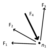
For the static analysis of tensegrity structures, three assumptions are made: the elements are only connected at the nodes forming friction-less joints, external forces are applied at the nodes only, and yielding and buckling are not considered. For simplification purposes, Figure 1 presents the forces acting on one node of an arbitrary tensegrity structure. If these forces are represented as a three-dimensional system of equations, and assuming a self-equilibrated structure without external forces, the forces acting on the elements can be expressed as
|
|
(2) |
| Figure 1. Forces acting on one node |
According to the force density method, the forces on each element can be replaced by a force-to-length ratio, called force density, as in
|
|
(3) |
where and represent the force densities of tensile and compressive elements, respectively, and is the length of the -th element. These force densities are then replaced into the Equation (2) and it becomes
|
|
(4) |
Although the diagram in Figure 1 represents the force in compression, its force is stated as positive in Equations (2) and (4) to maintain uniformity in the formulation of these expressions. However, the force density corresponding to this element is expected to have a negative value as a necessary condition for the existence of equilibrium in the node. The necessary and sufficient stability conditions for tensegrity structures can be found in Zhang and Ohsaki [20]. Equation (4) can also be expressed in a matrix form as
|
|
(5) |
The matrix containing the nodal coordinates is the so-called equilibrium matrix and the column vector comprised of the force densities is known as the force density vector . It should be noted that the previous Equation (4) contains the equilibrium equations for a single node only; for a full tensegrity structure with elements and nodes, this system of equations will present 3 equations and the size of matrices and will increase accordingly. Using these definitions, it is possible to write Equation (5) in the general form
|
|
(6) |
As proposed by Gómez Estrada et al. [21], if there is a matrix that contains the nodal coordinates , the equilibrium matrix can be described as
|
|
(7) |
The rows of the equilibrium matrix represent the projections along , and axes of the lengths of the elements that concur at a given node [22]. Each column of the matrix represents the magnitude and direction of the projected distances between the and , , nodes that comform each member. The self-stressed condition of tensegrity structures is observed from the rank of and its rank deficiency
|
|
(8) |
where relates to the number of states of self-stress, or sets of force densities, that solve Equation (6).
2.2 Affine motions
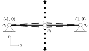
As any other self-standing structure, without fixed supports, tensegrities present the standard rigid body motions: rotation and translation along , and axes. However, the presence of tensile components introduces a third type of affine motion, the infinitesimal mechanisms, as described in Figure 2. Defined by Zhang and Ohsaki [6] as sufficiently small nodal displacements that maintain the length of all the elements unchanged, these motions are allowed by the flexibility of the cables and the pin joints. The presence of these mechanisms justifies the classification of tensegrity structures as kinematically indeterminate, as the structures become unstable when there is no prestress. When considered as a pin jointed structure, tensegrities are special cases, since they are also catalogued as statically indeterminate because their elements carry prestress when no external load is present.
|
| Figure 2. Infinitesimal mechanism in a two-element mechanism |
The equilibrium matrix is useful for the analysis of the kinematics of tensegrity structures as well, particularly its affine motions. As described by González and Luo [23], the singular value decomposition of can calculate the right singular vectors, whose last vectors correspond to its null space. Likewise, it can bring the 3 left singular vectors, associated to the transpose of matrix . The principle of virtual work states that if a particle is in equilibrium, the total virtual work done by the forces acting on the particle is zero for any virtual displacement of this particle; using this principle [24], it can be proved that
|
|
(9) |
where is known in structural analysis as the compatibility matrix. This equivalence brings a kinematic significance to the left singular vectors of , as it can be defined that they contain the affine motions of the tensegrity structure
|
|
(10) |
These vectors represent the displacement vectors that satisfy the compatibility equation
|
|
(11) |
From a physical point of view, the vectors describe a small motion of the nodes relative to their original position, and the entries in correspond to the set of components of this motion for all the nodes. If is the vector containing the initial nodal coordinates, the sets of coordinates for the affine motions can be computed as
|
|
(12) |
For a tensegrity in three dimensions, the six rigid body motions can be restricted by fixing some nodes; on the other hand, the remaining affine motions corresponding to the infinitesimal mechanisms cannot be removed, but these can be stabilized if the prestress is increased. The remaining left singular vectors include all the possible modes of displacement of the system that require the change in length of one or more of the elements.
2.3 Removing fixed nodes
For the kinematic characterization of a constrained tensegrity structure, it is desirable, and convenient, to remove the rows of from Equation (7) corresponding to the fixed nodes ; by omitting these rows, the rigid body motions are ruled out of the computations. It is also desirable to remove from Equation (7) the columns of that represent the members connecting solely these fixed nodes. This step is done because the components of the forces that these entries represent correspond to the reactions of the fixed nodes; for the self-equilibrium analysis of tensegrity structures, only internal forces should be considered.
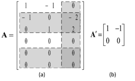
This process can be demonstrated considering the mechanism presented in Figure 2. Although it is not a tensegrity structure, the result can be extended to tensegrities without loss of generality. It can be assumed that nodes and are linked by a cable, and and are also connected by a cable; if free-standing, and can be considered as joined by a bar. This system presents all its affine motions, including rigid body motions and infinitesimal mechanisms. If it is desired to fix this structure, nodes and can be restricted; because of redundancy, the bar that connects the fixed nodes is also removed. Figure 3a presents the equilibrium matrix of the unconstrained geometry, with the expected size ; highlighted are the rows corresponding to the forces on the and axes of the fixed nodes and , as well as the column representing the bar that connects them. Once these entries are removed, a reduced equilibrium matrix is formed, detailed in Figure 3b; its size, for a -dimensional structure, is then , where represents the elements that have been fixed.
|
| Figure 3. Equilibrium matrix of a cable-bar system |
Using the software MATLAB, the singular value decomposition of can be calculated as
|
|
(13) |
where the matrix in the middle represents the singular values of as entries in its diagonal. The zero entry in the diagonal represents the null space of , describing , corresponding to the state of self-stress . This results in a left nullspace of with a dimension of as well. Because the rigid body motions are constrained, this value can only represent the affine motion corresponding to an infinitesimal mechanism and is given by the vector from the left singular vectors.
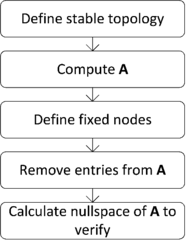
This mechanism can be verified from an inspection of Figure 2, where it is evident that the only motion that the free node can present is a displacement along the axis. The presence of only one affine motion confirms that the rigid body motions have been restricted. The algorithm for removing fixed nodes is resumed in Figure 4.
|
| Figure 4. Algorithm for the restriction of nodes |
3. Results
The previously described algorithm can be demonstrated by means of two examples: a single unit and a two-stage tensegrity structure.
3.1 Three-bar single unit
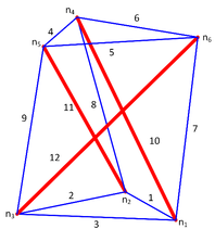
As the smallest 3D tensegrity structure, the three-bar tensegrity is an ideal analysis subject, since it has the minimum number of elements and equations. Assuming a structure with a height of 100 mm and a radius of 40 mm, and following the topology conditions described by Skelton and De Oliveira [11], the geometry shown in Figure 5 can be obtained. In this figure are represented the twelve elements, nine cables in blue and three bars in red; the six nodes are indicated with the symbol .
|
| Figure 5. Free-standing three bar tensegrity structure |
Following Equations (1) and (7), the matrix of the self-standing structure can be computed, as shown in Table 1, with a size of . In this arrange, the force equations for all the nodes are represented, as well as the contribution of all the elements. The entries of the matrix of nodal coordinates may be calculated with the parameters given above following [11]. Using MATLAB, the nullspace of is estimated, resulting in . From Equation (11), this value indicates the presence of affine motions, or six rigid body motions and one infinitesimal mechanism.
| 60,0 | 0 | 60,0 | 0 | 0 | 0 | 5,36 | 0 | 0 | 74,6 | 0 | 0 |
| -60,0 | 0 | 0 | 0 | 0 | 0 | 0 | 14,64 | 0 | 0 | -20,0 | 0 |
| 0 | 0 | -60,0 | 0 | 0 | 0 | 0 | 0 | -20,0 | 0 | 0 | -54,6 |
| 0 | 0 | 0 | -34,6 | 0 | -69,3 | 0 | -14,64 | 0 | -74,6 | 0 | 0 |
| 0 | 0 | 0 | 34,6 | -34,6 | 0 | 0 | 0 | 20,0 | 0 | 20,0 | 0 |
| 0 | 0 | 0 | 0 | 34,6 | 69,3 | -5,36 | 0 | 0 | 0 | 0 | 54,6 |
| -34,6 | 0 | 34,6 | 0 | 0 | 0 | -20,0 | 0 | 0 | -20,0 | 0 | 0 |
| 34,6 | 69,3 | 0 | 0 | 0 | 0 | 0 | 14,64 | 0 | 0 | 74,6 | 0 |
| 0 | -69,3 | -34,6 | 0 | 0 | 0 | 0 | 0 | 5,36 | 0 | 0 | -54,6 |
| 0 | 0 | 0 | 60,0 | 0 | 0 | 0 | -14,64 | 0 | 20,0 | 0 | 0 |
| 0 | 0 | 0 | -60,0 | -60,0 | 0 | 0 | 0 | -5,36 | 0 | -74,6 | 0 |
| 0 | 0 | 0 | 0 | 60,0 | 0 | 20,0 | 0 | 0 | 0 | 0 | 54,6 |
| 0 | 0 | 0 | 0 | 0 | 0 | -100 | 0 | 0 | -100 | 0 | 0 |
| 0 | 0 | 0 | 0 | 0 | 0 | 0 | -100 | 0 | 0 | -100 | 0 |
| 0 | 0 | 0 | 0 | 0 | 0 | 0 | 0 | -100 | 0 | 0 | -100 |
| 0 | 0 | 0 | 0 | 0 | 0 | 0 | 100 | 0 | 100 | 0 | 0 |
| 0 | 0 | 0 | 0 | 0 | 0 | 0 | 0 | 100 | 0 | 100 | 0 |
| 0 | 0 | 0 | 0 | 0 | 0 | 100 | 0 | 0 | 0 | 0 | 100 |
As mentioned before, for robotic applications such as positioning or active shape control, it is desirable to fix the bottom nodes of the tensegrity structure to avoid rigid body motions. In the case of the three-bar structure, nodes , and are restricted, allowing the motion of the system without displacement. Because the distance between these nodes will not change, the elements , and can be removed.
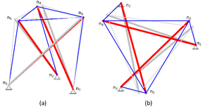
The rows , corresponding to the components are then deleted from matrix A; in the same way, columns 1, 2 and 3, corresponding to , and are also deleted, resulting in the matrix described in Table 2. The nullspace of the reduced equilibrium matrix can be calculated, resulting in ; this value is expected, as the structure is still self-standing and the fixed nodes only remove motions, so a prestress set is yet required. Because is square, its left nullspace is also 1, indicating the presence of . Since the structure is fixed, this motion can only correspond to an infinitesimal mechanism. Figure 6a shows the resulting structure, where it is seen how the bottom nodes are fixed and the cables connecting them have been removed; the geometry in equilibrium, and the excited mode are also presented, where the latter is described as the shadow geometry. The rotation of the top nodes produced by the infinitesimal mechanism can be observed more clearly in Figure 6b.
| -34,6 | 0 | -69,3 | 0 | -14,64 | 0 | -74,6 | 0 | 0 |
| 34,6 | -34,6 | 0 | 0 | 0 | 20,0 | 0 | 20,0 | 0 |
| 0 | 34,6 | 69,3 | -5,36 | 0 | 0 | 0 | 0 | 54,6 |
| 60,0 | 0 | 0 | 0 | -14,64 | 0 | 20,0 | 0 | 0 |
| -60,0 | -60,0 | 0 | 0 | 0 | -5,36 | 0 | -74,6 | 0 |
| 0 | 60,0 | 0 | 20,0 | 0 | 0 | 0 | 0 | 54,6 |
| 0 | 0 | 0 | 0 | 100,0 | 0 | 100,0 | 0 | 0 |
| 0 | 0 | 0 | 0 | 0 | 100,0 | 0 | 100,0 | 0 |
| 0 | 0 | 0 | 100,0 | 0 | 0 | 0 | 0 | 100,0 |
|
| Figure 6. Three-bar tensegrity structure with fixed nodes |
3.2 Tensegrity column
As demonstrated in the construction of sculptures, multistage tensegrity structures, and complex tensegrities in general, can also benefit by the remotion of rigid body motions; it prevents towers from tipping over because of the wind and rain, and allows asymmetric structures to stand. The method here presented can also be applied for restricting this kind of tensegrity.
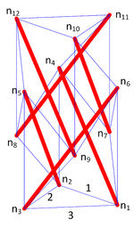
For this example, a two-stage tensegrity structure, with three bars per stage, a radius of 75 mm and a height per stage of 100 mm is assumed. The topology follows the numerical approach proposed by Tibert [25] for multi-stage tensegrity masts, based on the force density method. The resulting geometry, shown in Figure 7, has a total height of 200 mm, thanks to the fifty-percent overlap between stages; the nodal coordinates in millimeters of the structure are presented in Table 3.
|
| Figure 7. Free-standing two-stage tensegrity structure |
| 75,0 | -37,5 | -37,5 | -37,5 | -37,5 | 75,0 | 37,5 | -75,0 | 37,5 | 37,5 | 37,5 | -75,0 | |
| 0,0 | 64,9 | -64,9 | 64,9 | -64,9 | 0,0 | 64,9 | 0,0 | -64,9 | -64,9 | 64,9 | 0,0 | |
| 0,0 | 0,0 | 0,0 | 200,0 | 200,0 | 200,0 | 100,0 | 100,0 | 100,0 | 300,0 | 300,0 | 300,0 |
Following Equations (1) and (7), the matrix A of the self-standing structure can be computed; because of its size of 36×24 it is not shown in this paper. The software MATLAB can be used again to calculate the null space of , resulting in . From Equation (11), this value indicates once again the presence of affine motions, or six rigid body motions and one infinitesimal mechanism. It must be clarified that the fact that these are the same values as for the single unit represents a coincidence and has no relationship with the characteristics of the stages.
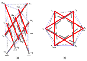
Once again, the bottom nodes , and are designated as the restricted nodes, and the rows of corresponding to the components of these nodes are removed, as well as the columns corresponding to the cables , and connecting these nodes. The null space of the reduced equilibrium matrix can be calculated, resulting in ; this value is expected, as the structure is still self-standing and the fixed nodes only remove motions, so a prestress set is yet required. Like the case of the single unit, the left null space of is also 1, indicating the presence of . This motion corresponds to an infinitesimal mechanism. Figure 8a shows the fixed structure, where it is seen how the bottom nodes are fixed and the cables connecting them have been removed; the geometry in equilibrium, and the excited mode are also presented, where the latter is described as the dashed geometry. The displacement of the nodes produced by the infinitesimal mechanism can also be observed from top in Figure 8b.
|
| Figure 8. Two-stage tensegrity structure with fixed nodes |
4. Conclusions
In this paper, a methodology for removing rigid body motions from a tensegrity structure has been presented. The formulation of the equilibrium equations for a tensegrity structure is described, and the significance of the vector spaces of the equilibrium matrix is discussed. The left null space of the equilibrium matrix contains the affine motions of the tensegrity structure, including rigid body motions and infinitesimal mechanisms. It was described that it is possible to restrict some nodes of a tensegrity to remove rigid body motions by deleting from the equilibrium matrix the rows corresponding to these nodes. Although not indispensable, it was explained that it is desirable to remove the columns corresponding to the elements connecting the fixed nodes as well, to bring the matrix to its reduced form. The left null space of this reduced form of the equilibrium matrix will contain the infinitesimal mechanisms of the structure.
Finally, two examples were presented, a single unit and a two-stage structure, to demonstrate the validity of the described methodology. Although only the infinitesimal mechanisms are illustrated in the figures of the numerical examples, the method here described can be combined with advanced control algorithms to design active structures with arbitrary layouts.
References
[1] Fuller B. U.S. Patent No. 3,063,521, 1962.
[2] Snelson K. The art of tensegrity. Int. J. Space Struct., 27(2-3):71-80, 2012.
[3] Pugh A. An introduction to tensegrity. University of California Press, Berkeley, 1976.
[4] Motro R. Tensegrity: Structural systems for the future. Kogan Page Science, London, 2003.
[5] Guest S.D. The stiffness of tensegrity structures. IMA J. Appl. Math., 76(1):57-66, 2011.
[6] Zhang J., Ohsaki M. Tensegrity structures. Springer, Tokyo, 2015.
[7] Connelly R., Back A. Mathematics and tensegrity. Am. Sci., 86:142-151, 1998.
[8] Pinaud J.P., Solari S., Skelton R.E. Deployment of a class 2 tensegrity boom. In Smart Structures and Materials 2004: Smart Structures and Integrated Systems, San Diego, 2004.
[9] González A., Luo A. Design and control of a tensegrity-based robotic joint. In IASS Annual Symposia, Hamburg, 2019.
[10] Martyniuk-Sienkiewicz K., Al Sabouni-Zawadzka A. Plate tensegrity structures controlled with self-stress. In XXIX R-P-S Seminar, Wroclaw, Poland, 2021.
[11] Skelton R.E., De Oliveira M. Tensegrity systems. Springer US, New York, 2009.
[12] Tran H.C., Lee J. Form-finding of tensegrity structures using double singular value decomposition. Engineering with Computers, 29(1):71-86, 2013.
[13] Wang Y.F., Xu X., Luo Y.Z. Form-finding of tensegrity structures via rank minimization of force density matrix. Engineering Structures, 227:111419, 2021.
[14] Liu K., Paulino G.H. Tensegrity topology optimization by force maximization on arbitrary ground structures. Structural and Multidisciplinary Optimization, 59(6):2041-2062, 2019.
[15] Lee S., Lee J., Kang J. A genetic algorithm based form-finding of tensegrity structures with multiple self-stress states. Journal of Asian Architecture and Building Engineering, 16(1):155-162, 2017.
[16] Li Y., Feng X., Cao Y. Monte Carlo form-finding method for tensegrity structures. In the International Symposium on Computational Mechanics, Hong Kong-Macau, 2009.
[17] Micheletti A., Williams W.O. A marching procedure for form-finding for tensegrity structures. J. Mech. Mater., 2(5):857-882, 2007.
[18] Faroughi S., Lee J. Design of tensegrity structures by minimizing static compliance. Lat. Am. J. Solids Struct., 11(4):631-648, 2014.
[19] González A., Luo A., Shi D. Reconfiguration method of tensegrity units using infinitesimal mechanisms. Engineering Computations, 36(6):1934-1949, 2019.
[20] Zhang J., Ohsaki M. Stability conditions for tensegrity structures. Int. J. Solids Struct., 44(11-12):3875-3886, 2007.
[21] Gómez Estrada G., Bungartz H.J., Mohrdieck C. Numerical form-finding of tensegrity structures. Int. J. Solids Struct., 43(22-23):6855-6868, 2006.
[22] Tran H.C., Lee J. Advanced form-finding of tensegrity structures. Computers & Structures, 88(3-4):237-246, 2010.
[23] González A., Luo A. Use of the SVD method for the stability analysis of tensegrity structures. Rev. Int. Métod. Numér., 34(1), 2018.
[24] Calladine C.R. Buckminster Fuller's “Tensegrity” structures and Clerk Maxwell's rules for the construction of stiff frames. Int. J. Solids Struct., 14(2):161-172, 1978.
[25] Tibert G. Deployable tensegrity structures for space applications. PhD Thesis, Royal Institute of Technology, Stockholm, 2002.Document information
Published on 31/03/22
Accepted on 16/03/22
Submitted on 13/11/21
Volume 38, Issue 1, 2022
DOI: 10.23967/j.rimni.2022.03.011
Licence: CC BY-NC-SA license
