1. Introduction
Composite overwrapped pressure vessels (COPV) are commonly used in aerospace applications and for hydrogen storage, because of weight savings when compared to the traditional metallic designs.
To further improve weight savings, the technological trend moved from type III (metallic liner), to type IV vessels (polymeric liners) using carbon fibre-reinforced polymers (CFRP). Additional performance improvements can be achieved with liner-less type V vessels, but different technological challenges arise from the design and manufacturing point of view, to exploit all the functionalities and achieve a cost-effective solution.
From the design perspective, one of the challenges to overcome in the design of type V vessels for cryogenic applications is how to account for the stresses in the structure resulting from:
- Severe thermal contraction, when considering the difference between curing and operating temperatures. Stresses appear at a microstructural level due to the mismatch between the thermal expansion coefficients of the fibre and the polymeric matrix;
- Chemical shrinkage taking place during the curing process [1]–[4].
Furthermore, in multidirectional laminates, such as those that constitute the CFRP pressure vessel walls, these effects are aggravated by the constraining effect of adjacent layers.
In this work, a 3D finite element model at meso-scale level of a COPV was developed to study the effects of thermo-mechanical residual stresses and the pressure load carrying capacity at cryogenic conditions. The material model was calibrated with experimental tests of the unidirectional composite at ambient and cryogenic temperatures.
2. Methodology
2.1. COPV description
The schematic representation of the conceptual design of the COPV is shown in Figure 1.
It corresponds to a cylindrical tank with ASME 2:1 ellipsoidal heads ( and ), length L=400mm and diameter D=300mm. The implemented lay-up is [(±30)3; ±40; ±60; 902].
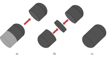
The manufacturing process follows an automated laying process of UD tapes with a ply thickness of 0.15 mm. The assembly of the whole vessel, schematically represented in Figure 2, is composed of three main stages: a) Deposition of the composite material over a solid mandrel to produce a half-shell which can be extracted after curing. The process is repeated to produce a second half-shell; b) The two half-shells produced in the previous stage are centred and assembled, with an internal reinforcement band of material securing the union between both shells; c) The resulting structure, akin to a liner, is laminated with additional layers of composite material, in order to obtain the final configuration.
2.2. Material modelling
The fibre-reinforced polymer system used in the development of this prototype corresponds to the commercially available carbon fibre-epoxy prepreg from SHD Composites. The material properties used in the current analysis were measured by mechanical testing, at room temperature (RT), 20°C, and at cryogenic temperature (CT), -196°C, and are presented in Table 1. The cryogenic tests were performed immersed in liquid Nitrogen.
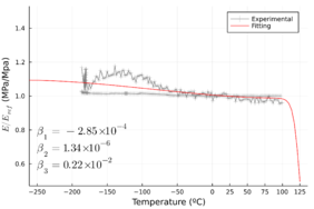
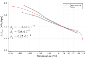
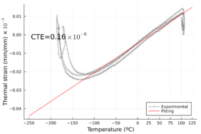
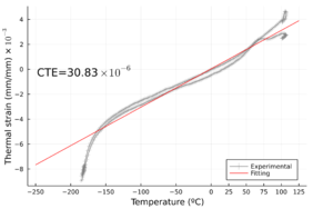
Since the temperature in operating conditions is expected to range from -190°C to 45°C, a thermo-mechanical study of the material behaviour was performed to evaluate the temperature influence on the elastic properties using a Dynamical Mechanical Thermal Analysis (DTMA) test machine. Figure 3 shows the normalized storage modulus (defined as the ratio of the current storage modulus to the room temperature measured storage modulus). It is clear how the material's elastic properties are more sensitive to the temperature in the transverse direction than in the longitudinal direction. The thermal expansion coefficient of the composite material was also characterized and presented in Figure 4.
| Physical Properties | Variable | Value at Amb. Temperature | Value at Cryo. Temperature |
| Density | [kg/m3] | 1500 | 1500 |
| Long. Elastic modulus | [GPa] | 102.00 | 112.00 |
| Trans. Elastic modulus | [GPa] | 6.38 | 11.32 |
| Long. Poisson’s ratio | [-] | 0.29 | 0.27 |
| Long. Poisson’s ratio | [-] | 0.34 | 0.37 |
| Long. Shear modulus | [GPa] | 3.38 | 6.55 |
| Trans. Shear modulus | [GPa] | 2.48 | 4.46 |
| Long. Thermal Expansion | [°C-1] | 0.16 × 10⁻⁶ | - |
| Trans. Thermal Expansion | [°C-1] | 30.83 × 10⁻⁶ | - |
| Long. Strength | [MPa] | 2002.12 | 1965.79 |
| Trans. Strength | [MPa] | 40.78 | 37.46 |
The curing process was simulated using the curing kinetics model proposed by Kamal [5] by applying the corresponding temperature cycle, shown in Figure 5, to the COPV model.
|
|
| (a) | (b) |
|
|
| (a) | (b) |
Finally, a 3D elastic-plastic constitutive model was used to simulate the mechanical behaviour of the composite material [6]. It considers the orthotropic behaviour of the unidirectional tape dominated in the longitudinal direction by the fiber, and in the transverse direction by the polymeric resin. Failure initiation and damage evolution are also considered using the modelling approaches proposed by Camanho et al. [7], [8].
2.3. Finite element model
To evaluate the COPV’s mechanical response under the different loading conditions, a finite element model of one-eighth of the structure is used with symmetry boundary conditions applied at the cut planes. This approach is a simplification because the three symmetry planes hold for the geometry but not for the material orientation of the plies. However, it constitutes a reasonable approximation for the purposes of this work.
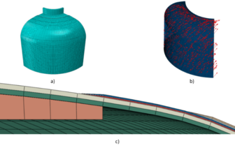
Figure 6 shows the mesh discretization for one-eighth of the pressure vessel. Each ply is modelled separately, with one solid element through its thickness. The fibre orientation follows the actual geodesic path followed by the tape during the tape-laying manufacturing process across the tank profile using [9]. Furthermore, the thickness of the plies in the dome region is modelled through Wang’s method [10] to capture the effects of tape overlap. All interfaces are modelled using a tie constraint for simplification.
Three different effects are to be considered when evaluating the COPV: the curing stresses, thermal contraction associated with exposure to cryogenic conditions and stresses resulting from internal pressurization. To better understand each contribution, these effects are to be studied in two distinct load cases involving: i) curing cycle, cool down to room temperature and pressurization; ii) curing cycle, cool down to cryogenic temperature and pressurization.
3. Results
3.1. Numerical
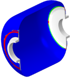
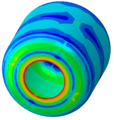
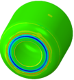
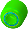
The proposed models were created and simulated to analyse the effects of the residual thermal stresses before the pressure loading conditions. Figure 7 shows the results for the stress distributions. It is clear that the higher residual stresses level are retrieved at the head region near the interface.
|
|
|
| (a) | (b) | (c) |
Figure 7.Residual stresses distribution after curing process at RT: a) Stress in fiber direction; b) Stress in the transverse direction; c) Transverse failure index.
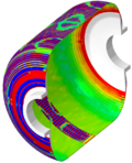
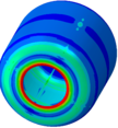
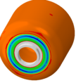
Figure 8 shows the stress distribution in the COPV after cooling down to the cryogenic condition (-196°C). Looking at the stress distribution in the COPV, the longitudinal stress levels (fiber direction) are low compared to fiber strength, but the transverse stress levels are considerably high because the thermal contraction during cooling of the composite material. Transverse failure is not triggered in the vessel, but high values near (0.80) are found in the whole geometry. Higher stress concentrations are identified at the transition zone between the composite wall and the metallic interface.
|

|
|
| (a) | (b) | (c) |
Figure 8. Residual stresses distribution after cooling process to CT: a) Stress in fiber direction; b) Stress in the transverse direction; c) Transverse failure index.
Analysing the pressure loading condition, Figure 9 shows the stress distribution in the COPV geometry at 25 bar for the RT loading condition, and 10 bar for the CT condition. The stress profiles show a similar distribution and transverse stresses are the most critical. The failure is identified near the metallic interface region because transverse damage is triggered in this zone for both conditions.
 
|
 
|
| (a) | (b) |
Figure 9. Stress distribution and transverse failure index a) RT condition and 25 bar of internal Pressure; b) CT condition and 10 bar.
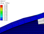
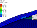
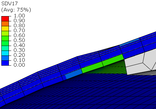
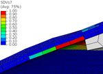
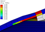
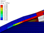
Looking into detail the damage evolution and failure mode of the COPV, Figure 10 shows the damage variable evolution (SDV17) for different pressure loading levels. The damage starts to evolve near 18 bar and completely crosses the full thickness at a pressure of 27 bar. Since the triggered failure mode is transverse damage, leakage instead of burst is expected in this conceptual design. The leakage is expected to appear between 24 bar and 27 bar of pressure.
|
|
|
| 15 bar | 18 bar | 21 bar |
|
|
|
| 24bar | 27bar | 30bar |
Figure 10. Transverse damage evolution at the critical zone as a function of the internal pressure.
A similar analysis is performed in the cryogenic condition, obtaining a pressure range between 9 bar and 12 bar. The damage pattern in the vessel under CT is different from RT because some damage is retrieved in the composite plies before pressure loading, due to the thermal contraction alone.
3.2. Experimental
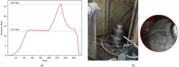
To evaluate the response of the COPV to internal pressurization, a burst test was performed. The pressure was manually regulated and increased throughout the test. The obtained values were recorded and displayed in the plot seen in Figure 11.
The test proceeded normally until a repeated snapping sound was heard from around 19 bar onwards, meaning that damage had been initiated in the material, but no leakage was detected. Finally, a maximum pressure of 26.0 bar was reached and a sudden pressure drop was measured, evidencing the onset of leaking, after which the tests were deemed completed. The COPV was then re-pressurized at a lower pressure so that the tank in the interior of the bunker could be safely inspected. The leak was seen to occur close to the transition from the cylindrical surface to the elliptical dome, as shown in Figure 11.
4. Conclusion
In this work, a numerical meso-mechanical analysis was implemented to understand the effect of the curing stresses and cryogenic conditions on the ply response of type V COPV. The results show that residual stresses from curing alone can achieve more than half of the ply transverse strength and induce premature transverse failure. Furthermore, the pressure loading capacity of the COPV is shown to decrease by more than 50% when exposed to cryogenic conditions. Finally, the predicted range of pressures for which leaking occurs at room temperature was found to be consistent with the experimental tests, where transverse failure is observed.
5. Acknowledgements
The current research work has been funded by the project UIDP/50022/2020 New Generation of Cryogenic Propulsion Systems for Future Launchers from LAETA - Laboratório Associado de Energia, Transportes e Aeronáutica, with the support of FCT/MCTES and PIDDAC (Programa de Investimentos e Despesas de Desenvolvimento da Administração Central) and by the “Fundo Europeu de Desenvolvimento Regional (FEDER)” for the financial support through the project “VIRIATO .: Veículo Inovador Reutilizável para Investigação e Alavancagem de Tecnologia Orbital” with reference POCI-01-0247-FEDER-046100.
Bibliography
[1] I. Baran, K. Cinar, N. Ersoy, R. Akkerman, and J. H. Hattel, “A Review on the Mechanical Modeling of Composite Manufacturing Processes,” Arch. Comput. Methods Eng., vol. 24, no. 2, pp. 365–395, Apr. 2017, doi: 10.1007/s11831-016-9167-2.
[2] N. Ersoy et al., “Development of the properties of a carbon fibre reinforced thermosetting composite through cure,” Compos. Part Appl. Sci. Manuf., vol. 41, no. 3, pp. 401–409, Mar. 2010, doi: 10.1016/j.compositesa.2009.11.007.
[3] J. A. Lavoie and E. Adolfsson, “Stitch Cracks in Constraint Plies Adjacent to a Cracked Ply,” J. Compos. Mater., vol. 35, no. 23, pp. 2077–2097, Dec. 2001, doi: 10.1177/002199801772661362.
[4] F. Danzi, D. Fanteria, E. Panettieri, and M. C. Mancino, “A numerical micro-mechanical study on damage induced by the curing process in carbon/epoxy unidirectional material,” Compos. Struct., vol. 210, pp. 755–766, Feb. 2019, doi: 10.1016/j.compstruct.2018.11.059.
[5] M. R. Kamal, “Thermoset characterization for moldability analysis,” Polym. Eng. Sci., vol. 14, no. 3, pp. 231–239, 1974, doi: 10.1002/pen.760140312.
[6] M. Vogler, R. Rolfes, and P. P. Camanho, “Modeling the inelastic deformation and fracture of polymer composites – Part I: Plasticity model,” Mech. Mater., vol. 59, pp. 50–64, Apr. 2013, doi: 10.1016/j.mechmat.2012.12.002.
[7] P. P. Camanho, M. A. Bessa, G. Catalanotti, M. Vogler, and R. Rolfes, “Modeling the inelastic deformation and fracture of polymer composites – Part II: Smeared crack model,” Mech. Mater., vol. 59, pp. 36–49, Apr. 2013, doi: 10.1016/j.mechmat.2012.12.001.
[8] P. P. Camanho, A. Arteiro, A. R. Melro, G. Catalanotti, and M. Vogler, “Three-dimensional invariant-based failure criteria for fibre-reinforced composites,” Int. J. Solids Struct., vol. 55, pp. 92–107, Mar. 2015, doi: 10.1016/j.ijsolstr.2014.03.038.
[9] J. Che, M.-G. Han, and S.-H. Chang, “Prediction of composite layer thickness for Type III hydrogen pressure vessel at the dome part,” Compos. Struct., vol. 271, p. 114177, Sep. 2021, doi: 10.1016/j.compstruct.2021.114177.
[10] Rongguo Wang, Weicheng Jiao, Wenbo Liu, and Fan Yang, “A new method for predicting dome thickness of composite pressure vessels,” J. Reinf. Plast. Compos., vol. 29, no. 22, pp. 3345–3352, Nov. 2010, doi: 10.1177/0731684410376330.
Document information
Published on 29/04/25
Accepted on 04/06/23
Submitted on 21/05/23
Volume 08 - COMUNICACIONES MATCOMP21 (2022) Y MATCOMP23 (2023), Issue Núm. 8 - Fabricación y Aplicaciones Industriales - Materiales y Estructuras - Modelos Numéricos, 2025
DOI: https://doi.org/10.23967/r.matcomp.2025.08.13
Licence: Other
Share this document
Keywords
claim authorship
Are you one of the authors of this document?

