Abstract
The adoption of Phase Change Materials (PCMs) in glazing systems was proposed to increase the heat capacity of the fenestration, being some PCMs partially transparent to visible radiation.
The aim of the PCM glazing concept was to let (part) of the visible spectrum of the solar radiation enter the indoor environment, providing daylighting, while absorbing (the largest part of) the infrared radiation.
In this paper, the influence of the PCM glazing configuration is investigated by means of numerical simulations carried out with a validated numerical model. Various triple glazing configurations, where one of the two cavities is filled with a PCM, are simulated, and PCM melting temperatures are investigated. The investigation is carried out in a humid subtropical climate (Cfa according to Köppen climate classifi-cation), and “typical days” for each season are used.
The results show that the position of the PCM layer (inside the outer or the inner cavity) has a relevant influence on the thermo-physical behaviour of the PCM glazing system. PCM glazing systems (especially those with the PCM layer inside the outermost cavity) can be beneficial in terms of thermal comfort. The assessment of the energy performance and efficiency is instead more complex and sometimes controversial. All the configurations are able to reduce the solar gain during the daytime, but sometimes the behaviour of the PCM glazing is less efficient than the reference one.
Keywords
Numerical simulations Phase change material ; Dynamic glazing systems Energy ; Thermo-physical behaviour
1. Introduction
During the last decades, highly glazed façades have become common in commercial and office building envelopes. Although considerable improvements have occurred in the field of glazing technology, especially as far as thermal resistance and solar control are concerned, the use of large glazed surface is often the cause of significant overheating problems and thermal discomfort. Thus, the positive architectural and environmental features of a conventional transparent building envelope (i.e., visual contact with the outdoor, exploitation of daylight and passive solar heating) are counterbalanced by the very little thermal inertia, and its negative influence on the energy balance of the building. In fact, the glazings capability of acting as an energy buffer is generally extremely low, giving rise to a high coupling between indoor and outdoor environment (especially in buildings characterised by large transparent envelopes), which results in high energy consumption for cooling and heating.
The adoption of Phase Change Materials (PCM) in combination with transparent elements first appeared in the Nineties, and some investigations concerning transparent building envelope components filled with PCM can be found in literature (Manz et al ., 1997 ; Ismail and Henríquez, 2002 ; Weinläder et al ., 2005 ; Ismail et al ., 2008 ). Although different configurations have been investigated along the years, the basic concept of the PCM glazing system is the same for all the possible layouts. In fact, the PCM layer is used to absorb and store (thanks to the latent heat of fusion) the largest part of the solar infrared (IR) radiation, and to let part of the solar visible (VIS) radiation enter the indoor environment. The aim of this class of technology is therefore to minimise the unwanted heat loss and solar gain thanks to the buffer effect provided by the PCM layer, but still allowing the utilisation of natural light for day-lighting purpose.
While the first concepts of PCM glazing systems were mostly developed for continental and cold climates, this technology shows some positive features for warm climates too, as illustrated in a more recent experimental activity (Goia et al., 2010 ).
Few products are available on the market and use in some low-energy building projects, but this technology has still not become a widespread solution.
The optimal configuration of a PCM glazing system is a very complex issue, since several different variables (e.g., the multi-layer structure, the PCM layer thickness, the temperature range of the phase change of the PCM) influence on the final behaviour of the system, and non-linear phenomena often occur. The aim of the work presented in this paper is to deepen the knowledge on PCM glazing systems with respect to two of the main variables that play a role in the problem: The location of the PCM layer and the nominal melting temperature of the PCM. The results illustrated in this paper concern the numerical analysis of south facing PCM glazing systems in a humid subtropical climate (Cfa — Köppen climate classification — Peel et al., 2007 ).
2. Materials and methods
2.1. PCM glazing system configurations
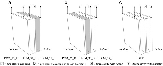
A total of 6 configurations of PCM glazing systems are proposed and simulated. The 6 configurations are obtained by the combination of 2 multi-layer structures and 3 different PCMs.
In particular, as far as the multi-layer structure is concerned, two different systems are simulated:
- a triple glazing with the outer cavity filled with PCM(codes: PCM_xx_O, Figure 1 b);
|
|
|
Figure 1. Scheme of the simulated triple-pane PCM glazing systems and reference glazing. |
- a triple glazing with the inner cavity filled with PCM (codes: PCM_xx_I, Figure 1 a). In both the configurations, the cavity that does not contain the PCM layer is filled with Argon. All the cavities (filled with PCM or with Argon) are 15 mm thick, the glass panes are all made of a 4mm thick clear glass. A low-E coating (ε =0.1) is always applied on one of the surfaces that faces the Argon-filled gap (see Figure 1 a–1b, layer 2).
As far as the PCMs is concerned, 3 different materials are considered:
- a paraffin whose nominal melting temperature is 35 °C (codes:PCM_35_y);
- a paraffin whose nominal melting temperature is 30 °C (codes: PCM_30_y);
- a paraffin whose nominal melting temperature is 25 °C (codes:PCM_25_y). The 3 paraffin waxes share the same optical and thermal properties but, obviously, the nominal melting temperature. A 10 °C melting range is maintained constant for the 3 paraffin waxes, and the latent heat associated to the phase change (i.e. 140 kJ/kg) is constant for the three waxes too. In Table 1 some of the physical properties of the PCM layers and glass panes are given.
| Physical quantity | Value |
|---|---|
| Glass pane | |
| Thickness | 4 mm |
| Density | 2500 kg m−3 |
| Thermal conductivity | 0.96 W m−1 K−1 |
| Specific heat capacity | 840 J kg−1 K−1 |
| Emissivity | 0.85 |
| Emissivity (low-E coating) | 0.10 |
| Paraffin wax | |
| Densitya | 800 kg m−3 |
| Thermal conductivity | 0.20 W m−1 K−1 |
| Specific heat capacityb | 2500 J kg−1 K−1 |
| Latent heat of fusion | 140 kJ kg−1 |
| Initial temperature of the phase change | 20/25/30 °C |
| Nominal (peak) melting temperature | 25/30/35 °C |
| Final temperature of the phase change | 30/35/40 °C |
a. Change in paraffin density between liquid and solid state is neglected.
b. Change in the specific heat capacity between liquid and solid state is neglected.
A triple-pane glazing (4/15/4/15/4) with both the cavities filled with Argon and a low-E coated surface (ε =0.1) is also simulated for reference purpose (code: REF) and illustrated in Figure 1 c.
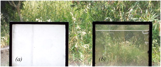
The visual appearance of a PCM glazing system (made of 2 glass panes and a 15 mm layer of commercial grade paraffin wax) is shown in Figure 2 . It is possible to observe the relevant difference that occurs between the solid state (Figure 2 a) and liquid state (Figure 2 b) of the PCM layer. The PCM layer is translucent when in solid state (i.e., most of the transmitted irradiance is scattered by the material, which behaves as a diffusive medium), while when the PCM layer in liquid state the direct-to-direct transmission mode is dominant, and the appearance is very similar to the one of a conventional glazing.
|
|
|
Figure 2. Visual appearance of the PCM glazing: with PCM in solid state (a), and with PCM in liquid state (b). |
2.2. Physical-mathematical model
The detailed description of the physical-mathematical model used to perform the numerical simulations and its validation is not given in this paper, but it can be found in Goia et al. 2012 . A short overview of the structure of the model and of some relevant assumptions are herewith instead given.
The model is a 1D nodal model, i.e., it only considers heat and light transmission along the z axis (normal to the glazings surface), while heat and light transfer along x -y axes is not considered. Three nodes are associated to each glass pane, while the PCM layer is represented by five computational nodes. Heat and light transport equations are implemented for the glass panes and the PCM layer, and energy conservation equations are written for each node and numerically solved to obtain the heat transfer process. The heat capacity of both the glass panes and the PCM is taken into account, so the model can simulate the behaviour of the PCM glazing system under dynamic conditions.
The following hypotheses were adopted for the model development:
- each node represents a layers that is supposed to be homogeneous;
- the glass surface is considered a grey body (for IR heat exchange with the surrounding environments);
- the surfaces of the outdoor and indoor environment are considered as black and/or grey body;
- convection within the PCM layer (when in liquid state) is neglected;
- radiative exchange between the two glass surfaces that face the cavity filled with PCM is also neglected;
- the optical properties of the glass panes are only function of the incidence angle of solar beam;
- the thermal properties of the glass panes are temperature independent;
- the optical and thermal properties of the PCM depend on the temperature (state of the PCM).
- More detailed information on the optical properties of the PCM layer can be found in Goia et al., in press .
As mentioned, the comparison between the simulations of a simple PCM glazing system (a double glazed unit with the cavity filled with PCM) and experimental data (Goia et al., 2010 ) of the same PCM glazing configuration was carried out to validate the model under dynamic conditions and in different seasons (Goia et al., 2012 ). It was shown that a good agreement between simulations and experimental data was reached as far as the surface temperature of the glazing system is concerned. The comparison between simulated and measured transmitted irradiances and heat fluxes did not always reach the desired accuracy, but the numerical simulations were able to replicate the physical phenomena, and the quality of the achieved results was also proved by satisfactory RSME (Root Square Mean Error). Thus the numerical tool seemed to predict well the thermo-physical behaviour of the system.
3. Simulations and data processing
3.1. Numerical simulations and boundary conditions
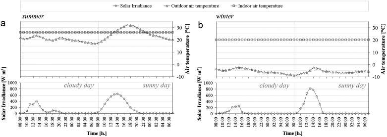
The behaviours of the various PCM glazing configurations are simulated in two seasons (summer and winter) in a humid subtropical climate. The simulated indoor environment has five adiabatic surfaces (three walls, floor and ceiling) that are at the same temperature of the indoor air. The façade (equipped with a different PCM glazing system for each simulation) is the only non adiabatic surface and faces south. Outdoor air temperature profile and sun irradiance profile (on the vertical plan) used in the simulation derive from actual measurements during the experimental campaign on a simple PCM glazing system (Goia et al., 2010 ). The indoor air temperature is maintained at the desired set point (26 °C in summer, 20 °C in winter). The hourly profiles of the environmental variables (boundary conditions) are illustrated in Figure 3 .
|
|
|
Figure 3. Boundary conditions (outdoor and indoor air temperature, solar irradiance on the outdoor vertical surface) of the days selected for the analysis: summer days (a) and winter days (b). |
3.2. Data analysis procedure
The thermo-physical behaviour of the glazing system configurations and the energy efficiency assessment are analysed considering two “typical” days each season: a sunny day and a cloudy day – the solar irradiance is by far the main driving force that influences the behaviour of these PCM-based systems, as highlighted by data collected during the above mentioned experimental campaign. The hourly profile of the indoor surface temperature is used to illustrate and analyse the thermal behaviour of the configurations.
The evaluation of the energy efficiency performance is carried out considering the energy that, on a daily base, enters (E+ ) (Eq. (1) ) and leaves (E− ) (Eq. (2) ) the indoor environment through the glazing. In particular, it holds:
|
|
( 1) |
|
|
( 2) |
where is the transmitted solar irradiance, and are the positive (entering the indoor) and negative (leaving the indoor) surface heat fluxes, 1 respectively.
4. Results and discussion
4.1. Thermo-physical behaviour
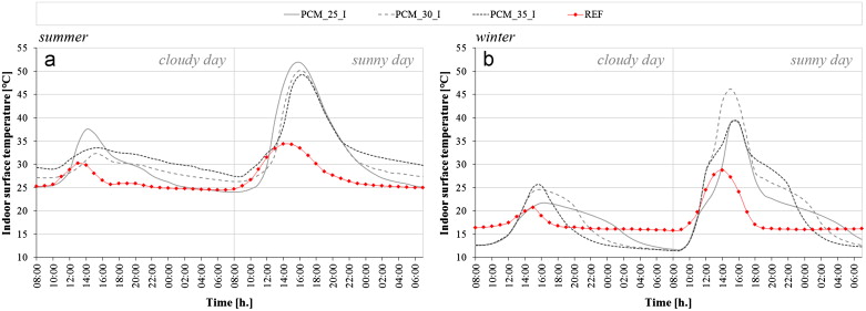
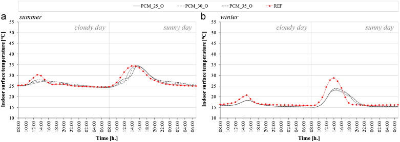
The hourly profiles of the surface temperatures of the 6 PCM glazing systems and the reference fenestration are illustrated in Figure 4 ; Figure 5 .
|
|
|
Figure 4. Hourly profile of the indoor surface temperature of the glazing systems PCM_25_I, PCM_30_I, PCM_35_I and the reference fenestration: summer days (a) and winter days (b). |
|
|
|
Figure 5. Hourly profile of the indoor surface temperature of the glazing systems PCM_25_O, PCM_30_O, PCM_35_O and the reference fenestration: summer days (a) and winter days (b). |
It can immediately be observed that the position of the PCM layer (inside the inner or the outer cavity) affects to a great extent the behaviour of the system.
During the daytime, the PCM_xx_I configurations (Figure 4 ) always show a higher surface temperature than the reference, regardless the season. This behaviour can be explained considering that the PCM layer acts as a solar collector, absorbing (part of) the solar irradiance that hits the glazing; the energy stored in the PCM layer is therefore far higher than the one stored in the reference glazing. In case of a cloudy day, the surface temperature of the PCM glazing systems is higher than the reference too, being even a limited amount of solar irradiance enough to increase the surface temperature of the glazing. This behaviour may have a positive influence on the indoor thermal environment during the winter season (increasing the global comfort condition and, above all, avoiding local discomfort due to cold vertical surfaces, especially from 17:00 to 24:00).
On the other hand, the indoor surface temperature drops approx. 5 °C lower than the reference during the winter nights in the case of PCM_xx_I fenestrations. This behaviour is due to the position of the low-E coating and to the slightly increased U-factor of the PCM glazing systems compared to the reference fenestration. The indoor thermal comfort conditions are negatively affected by this temperature drop.
The various PCMs show different dynamics (the lower the melting temperature, the faster the melting process and the slower the re-solidification process), but the behaviour is very similar. In summer, the temperature profile is always higher than the reference one, for all cases regardless the PCM used, with unfavourable consequences on the thermal comfort. Therefore, even if the PCM_xx_I configurations may provide some advantages in winter daytime, they cause considerable drawbacks in summer and during cold winter nights.
The PCM_xx_O configurations (Figure 5 ) show a better performance, thanks to their ability to reduce the fluctuations in the surface temperature profile and to provide a more stable surface temperature. It thus contributes to more stable thermal conditions in the indoor environment. In particular, during the summer days, these configurations are able to smoothen (especially in cloudy days) and delay (especially in sunny days) the peak of the surface temperature profile and to maintain a more comfortable indoor surface temperature. In winter time, problems may arise during cloudy days, when the PCM layer is scarcely activated by the limited solar energy and it acts mainly as a shading device. However, the performance during sunny days is still appreciable.
If compared to the reference fenestration, a slightly lower surface temperature is observed during the winter night time. This is probably due to the a slightly increased U-factor, being the thermal resistance of the PCM layer lower than the one that occurs within the cavity filled with Argon of the reference fenestration.
4.2. Energy efficiency performance
The energies that flow through the PCM_xx_I and PCM_xx_O glazing systems are reported in Figure 6 ; Figure 7 , respectively. The layer structure has a wide impact on the behaviour of the glazing system, but the adopted PCM melting temperature affects the performance of the system too.
|
|
|
Figure 6. Daily positive (E+ ) and negative (E− ) energy flux through the glazing systems PCM_25_I, PCM_30_I, PCM_35_I and through the reference fenestration: summer days (a) and winter days (b). |
|
|
|
Figure 7. Daily positive (E+ ) and negative (E− ) energy flux through the glazing systems PCM_25_O, PCM_30_O, PCM_35_O and through the reference fenestration: summer days (a) and winter days (b). |
As far as the PCM_xx_I configurations are concerned, the following observations can be made.
In summer, during a cloudy day, the E+ is reduced by more than 50% with the 30 °C paraffin and by about one third if the 35 °C paraffin is used instead. In sunny days, both the 30 °C and 35 °C paraffin waxes reduce by about 15% the E+ . The E− is always zero, because of the discharge phase of the PCM that keeps on releasing heat towards the indoor environment even during the night. The PCM_25_I system shows a behaviour that is similar to the reference glazing one, since the indoor/outdoor air temperatures are always within the melting range of the PCM or higher, and the PCM is hence always activated (in phase transition).
In sunny winter days, it is remarkable how the PCM_xx_I configurations are able to reduce the energy losses E− (PCM_25_I: more than −70%; PCM_30_I: more than −60%; PCM_35_I: about −50%), by converting and storing part of the income solar radiation during the daytime. In fact, the E+ is also reduced of more than 40% (PCM_25_I and PCM_35_I). The same behaviour can be noticed for the cloudy days too, but with lower values. The systems show a good performance if the goal is to lower the solar gain during the daytime and to reduce the energy losses during the nigh.
The PCM_xx_O configurations show a notable performance in summer when, in sunny days, they are able to reduce of about one third (PCM_30_O and PCM_35_O) and of about one fourth (PCM_25_O) the E+ . In cloudy days, the reduction is in the range of −70÷75%.
The E− is generally reduced too, both on sunny and cloudy day (with the exception of PCM_35_O under cloudy weather conditions), due to the discharge phase of the paraffin. However, this issue seems not to be of particular relevance in summer.
A more complex behaviour occurs during winter, when the PCM_xx_O systems are able to lower the solar gain during the daytime (as the PCM_xx_I configurations do), but do not reduce the energy loss E− during the night This is due to the position of the PCM layer (i.e., the outermost cavity), which increases the dissipation towards the outdoor environment of the heat stored during the daytime within the PCM layer. This effect is even more enhanced by the adoption of a low-E coating on the glass pane that faces the indoor environment, which reduces the radiative heat exchange through the innermost cavity. In cloudy days, because of the lower thermal resistance of the PCM glazing (if compared to the reference fenestration) and of the poor activation of the PCM layer caused by the lack of solar energy, the heat loss through the PCM_xx_O systems is higher than through the reference (about +30%). In sunny days, the E- is slightly increased in the case of the PCM glazing, but E+ and E− are of the same order, so these configurations can be virtually considered a “nearly adiabatic” surface, on a 24 h basis – due to the facts that the magnitude of the positive and negative energy flows is low and that the positive energy flow is equivalent to the negative one.
5. Conclusion
Different PCM glazing configurations have been tested by means of a numerical analysis to assess their behaviours with respect to the energy efficiency and thermal performance in a humid subtropical climate.
These glazing systems (especially the ones with the PCM layer that faces the outdoor) can be beneficial in terms of thermal comfort.
A more complex evaluation is needed when the energy performance is addressed instead. All the systems are able to reduce the solar gain during the daytime, acting like solar shading device, and to store a certain amount of heat within the paraffin layer. The release of this energy is only driven by the boundary conditions, so a limited active control over this process is possible.
In general, all the configurations are able to reduce the direct solar energy transmission and to shift the heat flux peak, when compared to the reference fenestration. This may allow a better control on the dynamics of the solar heat gain and, especially in summer, a more stable indoor environment. However, when the daily energy is concerned, all the configurations drastically reduce the solar free gain, with a potential negative impact on the total energy balance of the building (especially in winter). Some configurations (with the PCM in the innermost cavity) even presents higher heat loss that the reference fenestration. Sometimes the behavior of the PCM-based glazing system is thus less efficient than the reference one.
Future analyses will concern simulations for longer periods (one week or the whole season), in order to take into account the effect of the previous days' boundary conditions—the time constant of the PCM glazing systems may be higher than just one day. Furthermore, numerical simulations in different locations are also planned in order to evaluate the efficiency of these systems in different climates.
Acknowledgements
The research is part of the project “SMARTglass”, co-financed by Regione Piemonte, Skyline—Strutture per l'Architettura srl and MBT srl , in the framework of Polight 2010 activity. Special thanks are due to Emiliano Carnielo for the original picture used in Figure 2 .
References
- Goia et al., 2012 Goia, F., Perino, M., Haase, M., 2012. A numerical model to evaluate the thermal behaviour of PCM glazing system configurations, Energy Buildings 54, 141–153
- Goia et al., in press Goia, F., Zinzi, M., Carnielo, E., Serra, V. Characterization of the optical properties of a PCM glazing system. Energy Procedia, In press
- Goia et al., 2010 Goia, F., Perino, M., Serra, V., Zanghirella, F., 2010. Experimental assessment of the thermal behaviour of a PCM grazing. In: Proceedings of IAQVEC 2010—The 7th International Conference on Indoor Air Quality, Ventilation and Energy Conservation in Buildings (Syracuse, New York, USA), 15–18, August 2010. Paper Ref. 21–34, pp. 1–8.
- Ismail and Henríquez, 2002 K.A.R. Ismail, J.R. Henríquez; Parametric study on composite and PCM glass systems; Energy Conversion and Management, 43 (2002), pp. 973–993 http://doi.org/10.1016/S0196-8904(01)00083-8
- Ismail et al., 2008 K.A.R. Ismail, C.T. Salinas, J.R. Henriquez; Comparison between PCM filled glass windows and absorbing gas filled windows; Energy and Buildings, 40 (2008), pp. 710–719 http://doi.org/10.1016/j.enbuild.2007.05.005
- Manz et al., 1997 H. Manz, P.W. Egolf, P. Suter, A. Goetzberger; TIM-PCM external wall system for solar space heating and daylighting; Solar Energy, 61 (1997), pp. 369–379 http://doi.org/10.1016/S0038-092X(97)00086-8
- Peel et al., 2007 M.C. Peel, B.I. Finlayson, T.A. McMahon; Updated world map of the Koppen–Geiger climate classification; Hydrology and Earth System Sciences, 11 (2007), pp. 1633–1644 http://doi.org/10.5194/hess-11-1633-2007
- Weinläder et al., 2005 H. Weinläder, A. Beck, J. Fricke; PCM-facade-panel for daylighting and room heating; Solar Energy, 78 (2005), pp. 177–186 http://doi.org/10.1016/j.solener.2004.04.013
Notes
1. The term surface designates the heat flux exchanged between the indoor surface of the glazing and the indoor environment. It includes the long-wave radiative heat flux and the convective heat flux.
Document information
Published on 12/05/17
Submitted on 12/05/17
Licence: Other
Share this document
Keywords
claim authorship
Are you one of the authors of this document?
