Abstract
The free vibration of the sewing needle is divided into lateral free vibrations and an axial free vibration. In this work a theoretical study that concerns the free lateral vibrations will be applied to the sewing needle by the use of Gorman’s Eigen values (Daniel, 1975) technique. The study will be divided into the following: needles with constant cross-section (with classical and non classical boundary conditions) and needles with variable cross-section (conical and stepped). For all the different shapes of needles (Gorman’s classifications) the linear natural frequency in stitches per min (SPM) will be calculated by the use of Gorman’s Eigen values via special tables and graphs. It was found that the linear fundamental natural frequencies of the following: clamped free sewing needle (CF) is 21,548 SMP, clamped simple sewing needle (CS) is 94,522 SMP while for free–free needle (FF) for n = 2 is 137,130 SMP. For each type the Eigen value β was selected due to the sewing needle boundary conditions. The ratio between the lowest (CF) linear natural frequency and the highest (FF) one is 16%. In this work the selected sewing needle material was steel with E = 206 GPa and specific weight 785,000 N/m3.
Keywords
Free vibration; Sewing needle design; Working speed of sewing needle
1. Introduction
Panovko [7] in his work has stated that it is difficult to indicate a domain of Engineering in which the study of elastic vibrations would not be urgent problem. Much attention is given by investigators to vibrations of structures of widely differing purposes: turbine rotors, aircraft, turbine blades, etc. Nowadays the garments and apparel industry are considered vital Engineering areas that require an emphasizing on its mechanical – machines – side such as the industrial sewing machines that have an important element i.e. the sewing needle where, it is a metallic bar from steel with a special configuration and structure. It is the highly accelerated part in the sewing machine where it has max allowable speed = 15 k SPM. The sewing needles have been subjected to too little studies that concern its vibration free, forced, modes, etc., to calculate the working speed of sewing needle. It is necessary to study its free vibration frequencies; in certain cases the vibrations impede the normal service or even directly endanger the strength by gradually promoting fatigue failure. In such cases the theory may indicate ways of reducing detrimental vibrations [7]. It is expected the security quality of the sewn fabric could be deteriorated as a result of the sewing needle vibrations [9]. The free vibrations mean the mechanical vibrations which are performed by a mechanical system (as sewing needle) having no energy supply from outside but they take place when the system is disturbed from its position of equilibrium and then suddenly released [7]. Gorman [3] has written that there are two commonly analyzed methods for having solution to the problem of free vibrations of bars (needles) and beams. The method, most frequently used was to solve the bar–beam-differential equations that express equilibrium between inertia forces and elastic restoring force, subject to prescribed boundary conditions. The second method is an energy method which consists essentially of utilizing the fact that in free vibration the sum of the beam-sewing needle-potential energy and the kinetic energy is constant. The Gorman method is highly applied in our work. Feodosev [2] has stated that the theory of vibrations is of special importance for applied problems: encountered in Engineering practice, among others in the designs of the machine – industrial sewing machines and structures.
There have been cases when an engineering structure designed for a large of safety to withstand static loading failed under the action of very small (relatively) small periodically acting force. In many cases stiff and very strong structures have proved unserviceable in the presence of varying forces whereas a similar lighter structure and not so strong at first glance – industrial sewing machines – sustain the same forces absolutely safely.
Varvak [8] has claimed that the special cases of the mechanical elastic system with single and multiple degrees of freedom could be tabulated for practical applications where the table has 3 columns: scheme of the mechanical system, degree of freedom and finally the natural frequency column. The table includes about 52 schemes of vibratory mechanical system.
Belyaev [1] has studied some important topics in the field of vibrations of the mechanical systems as the effect of the vibration resonance on the value of the stress in the machine elements – sewing needle – during the vibration process. In addition the calculation of the equivalent mass of the vibratory system has been carried out where for example sewing needle – as a cantilever beam the equivalent mass is FLv/3g [v – needle’s material specific gravity, L – length of the sewing needle and g – gravitational acceleration and F – cross-sectional area].
Panamarev [6] has studied extensively the vibrations of the coil spring as longitudinal (axial) or lateral (transverse) under different boundaries conditions. Also the axial vibration of turbine blades was evaluated by the way all the studies of Panamarev [6] were shifted to the Engineering practical applications and could be efficiently used in the industrial sewing machines as a point of our view [4].
2. Mathematical approach
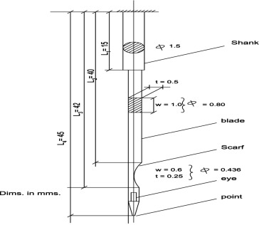
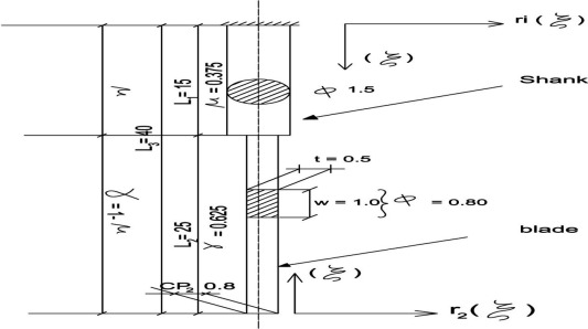
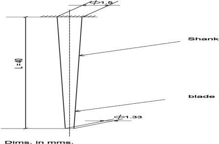
The actual configuration of the sewing needle [9] is shown in Fig. 1. The first part of the Mathematical Approach will be devoted to the needles with constant cross sections and with classical and non-classical boundaries.
|
|
|
Figure 1. Industrial sewing machine needle. |
2.1. Sewing needles with circular constant cross section and with classical boundary conditions
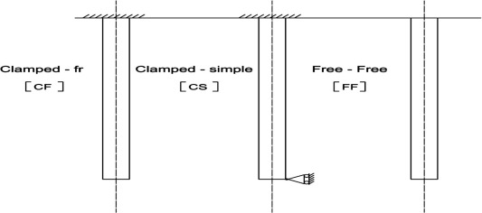
The calculation Scheme [line diagram] is shown in Fig. 2a.
|
|
|
Figure 2a. Sewing needles with classical boundary conditions and with constant cross sections. |
The mean value of the needle diameter is calculated by the use of the weighted inertia of cross sections
|
|
(1) |
|
|
|
|
Due to the Engineering experience and practice, the value of average needle diameter = 0.89 mm is reasonable.
The transfer of the actual configuration of the sewing needle from a bar with variable cross section to a bar with constant cross section by using the weighted average of the needle area inertia of cross section is an approximated method due to the small differences in the needle diameter along its length. The more accurate approximated technique is the method of the Russian Scientist Jemochken [5].
2.1.1. For the sewing needle with constant cross sections and with classic boundaries conditions
Due to Gorman [3]
|
|
(2) |
|
|
(3) |
where – density of sewing needle material (steel) , – Sewing needle cross-sectional area, – circular natural frequency, – sewing needle overall length, – Young’s modules for sewing needle material (steel) , – area moment of inertia of the needle cross section, – Eigen value in sewing needle vibration problem via special table, linear natural frequency. The sewing needle modal shape as a function of , x − a variable distance along the needle axis for different bounding conditions is as follows:
- The equation of the modal shape for Clamped-free [CF] needle is
|
|
(4) |
|
|
(5) |
The equation of the modal shape for clamped-simple needle [CS] is
|
|
(6) |
|
|
(7) |
The modal equation for free–free sewing needle (FF) is as follows:
|
|
(8) |
|
|
(9) |
The database of the sewing needle is as follows:
Length =
Diameter =
Area inertia of cross section
|
|
|
|
|
|
|
|
The Eigen value for different boundary conditions and for different modes [3] are shown in Table 1.
| Mode | Free–free | Clamped-free | Clamped-simple |
|---|---|---|---|
| 1 | 0 | 1.875 | 3.927 |
| 2 | 4.73 | 4.694 | 7.069 |
| 3 | 7.853 | 7.855 | 10.210 |
| 4 | 10.95 | 10.96 | 13.332 |
Source: Gorman [3].
The calculation of the natural frequencies for the previous stated needle in (SPM) is as follows:
- Clamped simple Sewing needle [CS] boundary conditions,
|
|
- Clamped free Sewing [CF] needle boundary conditions,
|
|
Free–free Sewing needle [CF] boundary conditions,
|
|
The summary of result is shown in Table 2.
| Mode | Free–free | Clamped-free | Clamped-simple |
|---|---|---|---|
| 1 | 0 | 21,548 | 94,522 |
| 2 | 137,130 | 135,051 | 306,285 |
2.2. Needle with constant cross sections and with non-classical boundary conditions
|
|
(10) |
where
dimensional linear spring constant
|
|
(11) |
– spring constant for linear coil spring, – needle overall length, – Young’s modulus for the sewing needle material (Steel) and I – area moment of sewing needle cross section.
Also the modal shape equation is as follows:
|
|
(12) |
where
|
|
(13) |
|
|
(14) |
where – Needle modal shape as a function of , – distance measured along the needle, fn – frequency of sewing needle vibration in nth mode, fCF – natural frequency of clamped free needle, and – measure of how far sewing needle frequency lies between limiting frequencies as shown by special Table 3, – Eigen value is appearing in needle’s vibrations in problems, – natural frequency of clamped simple Sewing needle, – clamped free and – clamped simple, CE – Clamped-Elastic (non-classical boundary conditions).
In our case, we can show the upper limit in an asymptotic fashion, for this reason the following relationship between is limited for intermediate late values of greater than 0.8.
|
|
(15) |
where is the value of at and any analyst of the tabulated data indicates that the previous Eq. (15) also gives frequency with error not greater than 1 percent [3].
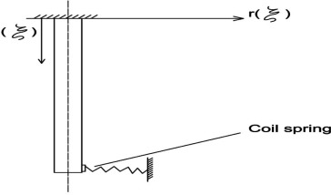
The calculations of the sewing needle with constant cross section and with non-classical boundary conditions – see Fig. 2b are the following: from special Table 3 we can find as follows: assume fabric elastic resistance coefficient k = 2000 N/m, then
|
|
|
|
|
Figure 2b. Sewing needle with non-classical boundary conditions with constant cross section. |
shown previously in Section (I),
- For clamped free sewing needle, n = 1
|
|
- For clamped simple sewing needle, n = 1
|
|
For our case – Fig. 2b with n = 1
|
|
=67.229 SPM. See Table 3.
| n | Needle with variable cross sec. | ||
|---|---|---|---|
| Stepped | Conical and circular | ||
| Nose cone | Truncated cone | ||
| 1 | 180,400 | 118,832 | 100,675 |
| 2 | – | – | – |
2.3. Sewing needles with variable cross section and with classical boundary conditions
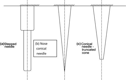
In this section, the variable cross sections sewing needles, as seen in Fig. 3 are divided into the following: (a) stepped needle (two sections), (b) nose conical needle and (c) truncated conical needle.
|
|
|
Figure 3. Sewing needles with variable cross section and with classical boundary conditions. |
2.3.1. Stepped sewing needle with two cross sections
The stepped sewing needle is shown in Fig. 4, where the equations of needle modes are as follows:
|
|
(16) |
|
|
(17) |
|
|
(18) |
|
|
|
Figure 4. Stepped sewing industrial machine needle. |
Then;
|
|
(19) |
|
|
(20) |
where
|
|
(21) |
The frequency (natural) is the same as in Eq. (2).
The database of the stepped sewing needle shown in Fig. 3a is as follows:
|
|
|
|
Then:
|
|
Return back to special Table 3 we can write for n = 1 and
|
|
For
|
|
2.3.2. Conical needle with circular cross sections
A. Nose cone needle
The needle configuration is shown in Fig. 5 from specified Table 3 we can find the ratio , and for n = 1 then
|
|
|
|
|
|
|
Figure 5. Conical incomplete sewing industrial machine needle. |
B. Truncated cone needle
The needle line diagram is shown in Fig. 5.
|
|
From specified Table 3 we calculate the following: Eigen value = 1.8, and see the sewing needle as truncated circular cone is shown in Fig. 5.
3. Conclusions and future visions
From the previous calculations for the different sewing needle configurations and cross sections, the following conclusions findings could be written:
- The transfer of the industrial sewing needle from a bar with variable cross section to a bar with constant cross section by the way of the weighted average of the actual needle area moments of its cross section is acceptable where the percentage error is 1%.
- The lowest fundamental linear natural frequency is 22 k stitches per min [SPM] for a clamped-simple [CS] sewing needle with classical boundary conditions and with constant cross section, while the highest value is 180 k for stepped sewing needle with classical boundary conditions.
- The clamped-elastic sewing needle with non-classical boundary conditions produced a fundamental natural linear frequency 67 k SPM, and the elastic resistance of the fabric was expressed by K = 2000 N/m as an assumption (it needs extensive experimental work).
- The average working speed of the industrial needle-practically is 3 k SPM which represents 14% of the fundamental linear natural frequency of the clamped-simple needle which is too safe [the safety could be accepted up to 70%].
- Seemingly the elastic resistance of the sewn fabric on the lower and of the needle is relatively high so that the needle with its frequency 22 k SPM could be considered clamped-simple (CS).
- The equation of the modal shape of each needle type and design as a function of (ξ) is written and could be represented graphically at different modes (n = 1, 2, 3, etc.) by the aid of Matlab software, and the variable of ξ is a function of (x ) equals to where x is a variable in the direction of the sewing needle length.
- The fundamental linear lateral free natural frequency is too high for the sewing needle due to several parameters as its mass per unit length (where it is too relatively small and the high modulus of elasticity of the steel, etc).
- The first fundamental linear natural frequency for the lateral free vibration of the sewing needle is too sufficient practically. The future vision is to carry out experimental work to measure the fundamental natural linear frequency-via specific practical techniques such as impacting the needle; in addition, the elastic coefficient of fabric resistance to the needle is needed to be intensively measured by innovating and advanced techniques. Lastly the axial vibratory mode shapes and natural linear fundamental frequencies are needed to practice the overall pattern of the sewing needle vibrations.
References
- [1] N.M. Belyaev; Strength of Materials, Russian Copy, Nayko-Press, Moscow, R.F.U. (1976)
- [2] V. Feodosev; Strength of Material; English Copy Mir published, Moscow, R.F.U. (1968)
- [3] Gorman I. Daniel; Free Vibrations Analysis of Beems L Shafter; John Wiley and Sons Press Ottawa University, Canada (1975)
- [4] Ibrahim A. El hawary; The Dynamic Balancing of the Heavy Packages of the Plied Continues Filament Lectures, TED, Alex University, Egypt (2015)
- [5] Ibrahim A. El hawary; The Vibrations of the Heavy Twisting Spindles used for Plying CF Yarns; Academy of Textiles, Moscow, State (MSAT), R.F.U. (1978)
- [6] C.D. Panamarev, et al.; The Basic Modern Method of the Machine Design Machine; Design Press, Moscow, R.F.U. (1952)
- [7] Ya Panovko; Elements of the Applied Theory of Elastic Vibrations; English Copy Vibrations Mir Publisher, Moscow, R.F.U. (1971)
- [8] Ed. Varvak, et al.; Reference Book of Strength of Material; Naykova Press, Kiev, Ukraine (1975)
- [9] G. Stylios, O. Sotomi, R. Zhu, Y. Xu, R. Deacon; The mechatronic principles for intelligent sewing environments; Mechatronic, 5 (2/3) (1995), pp. 309–319
Document information
Published on 12/04/17
Licence: Other
Share this document
claim authorship
Are you one of the authors of this document?
