1 Introduction
When talking about carbon fiber reinforced plastics (CRFP) in general, manufacturing costs represent a high percentage of total product cost, reaching 70 % of cost in high added value applications [1]. This is one of the main barriers for a higher implementation of these materials.
Manufacturing processes for large sized and high performance composite parts are based on the use of pre-impregnated materials (prepregs) that are cured in autoclave to get the necessary final properties. Given the high impact of the material itself, the storage and the use of autoclave in the part final costs, new materials and manufacturing processes are vital for cost reduction.
With this objective, main resin and carbon fiber manufacturers are developing dry materials for manufacturing out-of-autoclave parts with similar (or better) mechanical properties if compared with prepregs. In fact, dry materials have already been homologated by some OEM’s for structural components in aerospace and are being homologated by others (i.e. Airbus, under the “Wing of the Future” programme [2]). Nevertheless, this homologation process has been done with low productivity processes (often hand-made), as there are no automated processes able to lay up with the required precision and with high productivity. It is necessary, thus, a technological solution to allow the introduction of dry materials and a reduction of total costs in high performance carbon composite parts.
1.1 State of the Art – Automated processes for fiber placement
Along the different types of automated lay-up processes for high performance composites, main efforts and investment in the last years have been focused on the development of prepregs lay-up.
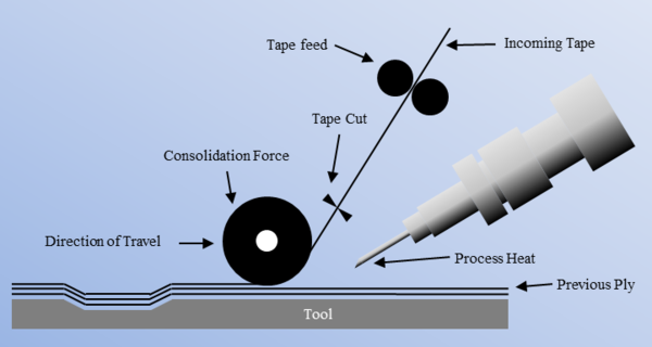
Nowadays, all sector leaders in structural parts manufacturing have specific machinery for automated deposition of prepregs. Existing technologies are Automated Tape Laying (ATL) and Automated Fiber Placement (AFP). ATL deposits prepregs tape with a maximum known width of 300 mm for a unique tape [3] or 4 tapes of 150 mm for a total 600 mm width [4]. AFP, on the other hand, uses prepreg tows for deposition, with a maximum known width of 770 mm (20 tows of 38.5 mm).
Choosing between ATL and AFP depends on the turning radius required by the surface. In other words, for parts with a higher curvature and/or more complex ply pattern AFP is more common, while in flat parts ATL is used more commonly. Moreover, even in a relatively big flat part, it would have relatively few continuous tape cycles, so AFP could improve ATL capacity for short course.
As said, AFP works with tow widths between 3.2 mm and 38.5 mm and machine speed could rise up to 75 m/min. As the tows are narrow, it is not necessary to include longitudinal/shape cut while the heating intends to add stickiness (TAC) to the prepreg. The main AFP machinery manufacturers are Automated Dynamics, Coriolis, Electroimpact, Fives, Ingersoll, MTorres, Microsam, etc.
ATL, on the other hand, works with tapes with a maximum width of 600 mm (4 tapes) and highest machine speeds are around 60 m/min. Main ATL machinery manufacturers are Fives and MTorres.
1.2 State of the Art – Use of dry carbon fiber
As said in the previous section, main efforts for automation in the last years have been made for prepregs deposition. Nevertheless, due to potential of liquid molding technologies, dry material deposition has also to be developed and automated. Although many carbon fiber manufacturers promote prepreg materials that once consolidated out-of-autoclave get similar properties than those cured in autoclave, the high quantity of variables that can be modified to get high compaction during liquid impregnation makes this option more attractive to avoid using autoclave [5].
Once focused on dry fiber deposition process, one of the areas which should be examined in greater depth is the different types of dry fabrics that can be used, analyzing the variables that can influence their performance when manipulating and placing them, and also the potential and advantages of each material. Different existing methods for automated or semi-automated deposition of dry carbon fiber fabrics will be analyzed.
1.2.1 Dry carbon fiber fabrics
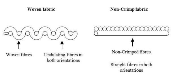
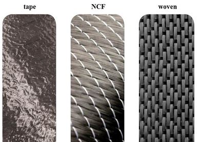
In addition to the unidirectional (UD) dry tows used by Dry Automated Fiber Placement (DAFP or DFP), many types of dry carbon multiaxial fabrics can be found: Unidirectional dry tape, Non-Crimp Fabric (NCF) and Woven. The dry unidirectional tape is a wider format of the tows used by the DFP machines, while the NCF and Woven materials are dry fibers disposed at different orientations per layer, creating the specific multiaxial fabric. Below, it is shown the difference between Woven and NCF:
Multiaxial NCF consist on multiple layers of fibers stitched together. The most used NCF’s are uniaxial, biaxial, triaxial and quadraxial fabrics, where the fiber tows are straight and with different orientations (0, +/-45, 90 degrees) to provide multidirectional properties.
NCF reinforced composites usually have better mechanical properties than traditional Woven fabric composites because fibers are not twisted nor intertwined. The drapability (capacity to be adapted to different geometries without creating wrinkles) and the permeability (capacity to be impregnated by the resin when parts are infused) are key parameters for final selection of the material with respect to the application. Furthermore, the resistance against delamination and resistance against impact are also of relevance [6].
The choice of woven or NCF, therefore, depends on the manufacturer and is influenced by the design of the part and the production process.
1.2.2 Dry carbon fiber fabrics
In the last years, many different development areas are arising around dry carbon fabrics placement methods. In general, 3 different types of approaches can be distinguished based on ATL/AFP, pick & place and/or roll & place technologies.
ATL/AFP based processes have benefited from the developments made for thermoplastic prepregs and have adapted the systems for the deposition of dry carbon fiber with binder (DAFP/DFP). There have been some attempts when introducing this process for wing skin and stringer manufacturing, but deposition rates are lower than those achieved with standard prepregs [7]. The most relevant developments in this area have been done by Coriolis and MTorres.
For processes based on pick & place, work cells have been developed following the next sequence. First, auxiliary cut is optimized on a pattern table. Then, a specific end-effector based on different grippers and customized for the final application picks different layers of fabrics, shapes them thanks to their drapability, and places onto the mold. The final preform is made through rigid plate or flexible membrane systems. The maximum deposition rate for these kind of processes is 60 kg/h [8], while traditional ATL/AFP deposition processes have 30/45 kg/h rates for flat lay-up or single curvature lay-up and 8.6 kg/h (or lower) for double curved geometries [9].
In the roll & place field, there are many R&D projects running around the dry fabric deposition, such as ATTOM project by Solvay [10], but no commercial solutions have been developed yet.
The ADMP® technology presented on this paper is a new way to handle dry materials (UD tapes, NCF and/or Woven) smoothly, accurately and quickly but without disturbing the fabric. It has application in concepts based on ATL/AFP or roll & place.
2 The challenge
Innovations in composite manufacturing are an important driver in the aerospace industry to reduce fuel consumption, meet emission targets and reduce noise. Boeing jumped from the 12 % usage of carbon parts on the 777 to 50 % on the 787, while Airbus moved from 10 % on the A340 to 25 % on the A380 and finally to 53 % on the A350XWB. Over 70 percent of the A350 XWB’s weight-efficient airframe is made from advanced materials combining composites (53 %), titanium (14 %) and advanced aluminum alloys (19 %). Most of the A350 XWB's wing is made of the lightweight carbon fiber reinforced plastic composites, including its upper and lower covers – measuring 32 meters long by six meters wide, making them the largest single aviation parts ever made from carbon fiber. Several factors are behind this increasing use of composite materials. The price of oil, the change in attitude towards environmental issue (e.g. ACARE [Advisory Council for Aeronautics Research in Europe] targets of 50 % reduction in CO2, a 50 % reduction in perceived noise and an 80 % reduction in NOx by 2020) and the predicted increase in airline traffic are all drivers that push the manufacturers to produce light-weight structures.
A heavier introduction of composite parts in the aerospace sector is dependent on 3 factors:
- Cost reduction: Considering that use of composites for wing parts will be more intensive in the future, the manufacturing process costs have to be reduced and this can only be made through automation. Existing technologies based on prepregs and/or dry tows are not cost-effective enough, so new solutions are needed.
- Productivity rate: Existing automated technologies have limited productivity rates, enough for current programs, but if composites are introduced in intensive programs (e.g. Airbus A320neo) with production rates over 60 aircrafts per month, new automated processes are needed.
- Fast ramp-up: As said, composites are expected to be introduced in programs of high production, which have faster ramp-up than current programs. So, a solution able to respond to a fast ramp-up of production is needed, without incurring into large investments.
3 The solution
The solution developed by DANOBAT to achieve the expected cost reduction, productivity increase and fast ramp-up is based on the Automated Dry Material Placement (ADMP®) technology.
3.1 Automated Dry Material Placement (ADMP®)
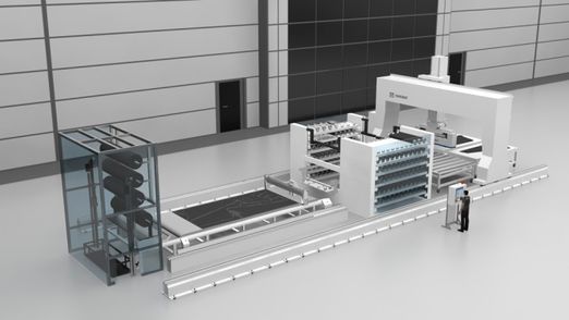
ADMP® technology enables the accurate and fast deposition of dry materials for the generation of preforms. The dry materials are supplied in rolls, either in raw material format with constant width or pre-cut to net size, and then layed on the mold for the later infusion or Resin Transfer Molding (RTM) process.
A typical approach for the skin manufacturing would consist of the next steps:
- 1. Raw material rolls are taken from the storage and then unwound on the cutting table.
- 2. The plies are cut on the table at net size, and use of material is maximized by nesting the plies.
- 3. The pre-cut net sized plies are rolled up by means of an ADMP® technology-based end effector, each in one different roll.
- 4. Each roll is transferred to an automatic store.
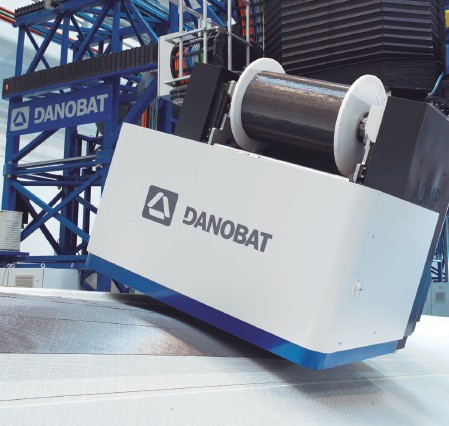
- 5. Rolls, each containing one ply, are deposited on mold following the layup sequence by means of an ADMP® end effector.
ADMP® offers much higher deposition rates than any other existing CFRP deposition technologies as the use of wide dry multiaxials enables a dramatic reduction of machine courses compared with other technologies which use narrower UD tapes or tows.
3.2 Main features of ADMP®
ADMP® improves the performance of other production systems in 4 fields:
- Deposition rate: Productivity achieved by ADMP® is higher than any other automation technology. Deposition rate by ADMP® is above 200 kg/h.
- Precision: Precision is guaranteed in ADMP® thanks to advanced control and positioning systems. Start and end point accuracy is under 1 mm, while the gap between plies is less than 3 mm. The precision for fiber angle deviation is +/- 3º.
- Geometries: ADPM® can place materials on complex geometries, including double curvature areas like wing skin molds, pressure bulkheads, etc. at any orientation. It has also the capacity for the layup of pre-kitted preforms.
- Range of materials: ADMP® makes feasible to work with a wide range of dry materials, such as unidirectional tape, NCF and Woven multiaxial, in carbon and/or glass fiber, with areal weights from 125 gsm to 1800 gsm in a unique end-effector. The roll width can vary from 100 mm to 2000 mm or even more (full-width ply).
4 Conclusions
Composites are the answer to the needs of aerospace industry in terms of weight reduction, but three important challenges must be taken up first: improving the cost efficiency, increasing the productivity rate and getting a faster ramp-up. Automation is key to achieve those challenges, but improvements have to be made, both with prepregs and dry materials.
ADMP® is a novel technology that takes automation to the next level: it offers higher production rates than existing technologies, makes the layup process more efficient and is scalable. It offers a great opportunity to automate the dry carbon fiber preform manufacturing.
References
[1] S. Haffner, “Cost modeling and design for manufacturing guidelines for advanced composite fabrication”, Thesis (Ph. D.), Massachusetts Institute of Technology, Dept. of Mechanical Engineering (2002).
[2] “Wing of the Future” Airbus, Filton, UK. http://www.airbusgroup.com/int/en/news-media/corporate-magazine/Forum-89/Wings-of-the-future.html
[3] Grimshaw, M. N., Grant, C.G. & Diaz J. L. “Advanced technology tape laying for affordable manufacturing of large composite structures” 46th International SAMPE Symposium and Exhibition. Long Beach, CA, 2001. Society for the Advancement of Material and Process Engineering. pp. 2484-2494.
[4] “Torreslayup – Automated Tape Layer Machine” Mtorres, Torres de Elorz, Spain. http://www.mtorres.es/en/aeronautics/products/carbon-fiber/torreslayup.
[5] Witik, R.A., Gaille, F., Teuscher, R., Ringwald, H., Michaud, V. & Manson, J.E. “Economic and environmental assessment of alternative production methods for composite aircraft components” Journal of Cleaner Production, Volumes 29-30 (2012): 91-102.
[6] Chen, F. & Hodgkinson, J.M., “Impact behavior of composites with different fibre architecture” Proceedings of the Institution of Mechanical Engineers, Part G: Journal of Aerospace Engineering, Volume 223 (2009): 1009-1017.
[7] Dell’Anno, G., Partridge, I.K., Cartié, D.D. & Tatam, R.P. “Automated manufacture of 3D reinforced aerospace composite structures” International Journal of Structural Integrity, Volume 3 (2012): 22-40.
[8] Campbell, Keith. “Affordable Composites Manufacturing – Grand Challenge” ACCIS Annual Conference. Bristol, United Kingdom, September 15, 2010. Advanced Composites Centre for Innovation and Science.
[9] Hallander, Per. “Towards defect free forming of multi-stacked composite aerospace components using tailored interlayer properties” Doctoral Thesis, KTH Engineering Sciences. Stockholm, Sweden, 2016.
[10] “Final Programme Report 2012-2016” Composites Innovation Cluster. Hempstead, UK, 2016. https://compositesuk.co.uk/system/files/documents/CiC Final Report - Compressed_0.pdf.
Document information
Published on 31/03/22
Accepted on 31/03/22
Submitted on 30/03/22
Volume 03 - Comunicaciones Matcomp17 (2019), Issue Núm. 3 - Procesos de Fabricación II y Materiales Avanzados, 2022
DOI: 10.23967/r.matcomp.2022.03.002
Licence: Other
Share this document
Keywords
claim authorship
Are you one of the authors of this document?
