Abstract
Polymethylacrylate (PMA) nanofibers membranes are fabricated by electrospinning technique and applied to the polymer matrix in quasi-solid-state electrolytes for dye sensitized solar cells (DSSCs). There is no previous studies reporting the production of PMA nanofibers. The electrospinning parameters such as polymer concentration, applied voltage, feed rate, tip to collector distance and solvent were optimized. Electrospun PMA fibrous membrane with average fiber diameter of 350 nm was prepared from a 10 wt% solution of PMA in a mixture of acetone/N,N-dimethylacetamide (6:4 v/v) at an applied voltage of 20 kV. It was then activated by immersing it in 0.5 M LiI, 0.05 M I2, and 0.5 M 4-tert-butylpyridine in 3-methoxyproponitrile to obtain the corresponding membrane electrolyte with an ionic conductivity of 2.4 × 10⁻³ S cm−1 at 25 °C. Dye sensitized solar cells (DSSCs) employing the quasi solid-state electrolyte have an open-circuit voltage (Voc) of 0.65 V and a short circuit current (Jsc) of 6.5 mA cm−2 and photoelectric energy conversion efficiency (η) of 1.4% at an incident light intensity of 100 mW cm−2.
Keywords
DSSCs; Quasi solid electrolyte; Electrospinning; Nanofibers
1. Introduction
Dye-sensitized solar cells (DSSCs) are currently attracting extensive academic and industrial interest from researchers who envision this technology to be a powerful and promising way to generate electricity from the sun at low cost and with high efficiency [1].
Recently, power conversion efficiencies of DSSCs using ruthenium complex dyes, liquid electrolytes, and platinum (Pt) counter-electrode have reached 13% (100 mW cm−2, AM1.5) by the Gratzel group [2]. Although DSSCs based on liquid electrolytes (triiodide/iodide redox couple in organic solvent) have already achieved high conversion efficiencies, the drawback of DSSCs using liquid electrolyte is the volatility of the electrolyte organic solvent and leakage in case of breaking of the glass substrates [1]. To solve these problems, gel polymer electrolytes are being investigated to substitute the liquid electrolytes [3], but they show a lower solar-to-electricity conversion efficiency because of their lower electron injection efficiency.
Gel polymer electrolytes such as poly(acrylonitrile) [4], poly(ethylene glycol) [5], and polymethylmethacrylate (PMMA) [6], have been used in quasi-solid-state DSSCs [7]. The polymer gel electrolytes must have relatively high ionic conductivities at room temperature, and stable in the presence of TiO2 and Pt nanoparticles [8]. In the late 1970s to early 1980s, many research groups demonstrated that ionic conduction was confined to the amorphous polymer electrolytes above their glass transition temperature (Tg) with the chain dynamics playing a critical role in the conductivity mechanism. Many new polymer electrolytes have been synthesized in an effort to minimize the crystallinity and to achieve even lower Tg values, thus enhancing chain dynamics and hence increasing the level of ionic conductivity [9].
Grätzel et al. [8] have pointed out that, the conductivity–temperature data of polymer-gelled electrolytes were better fit by the Vogel–Tammann–Fulcher (VTF) Eq. (1)[10],
|
|
(1) |
where σ is the ionic conductivity of the electrolyte including the oxidized redox couples which is related to their diffusion coefficients, T is the absolute temperature, A and B are constants and T0 is the temperature at which the diffusion of ions ceases to exist and may be considered as the glass transition temperature of polymer-gelled system. So by using the polymer with lower Tg to gel the electrolyte system in order to decrease T0, the conductivity should be increased.
Polymethylacrylate (PMA) has an amorphous nature and low glass transition temperature (Tg = 6 °C, lower than polymethylmethacrylate (PMMA) Tg = 105 °C) [11], which encouraged to use it as a polymer membrane in quasi-solid-electrolyte DSSC.
Tu et al. [12] compared between poly(methyl acrylate) (PMA), poly(vinyl acetate) (PVAc) and poly(n-isopropylacrylamide) (PNIPAAm) with their respective Tg of 6, 32, and 145 °C as gel polymer electrolyte for DSSC. The light-to-electricity conversion efficiencies of DSSCs gelled by PMA, PVAc, and PNIPAAm were 7.17%, 5.62%, and 3.17%, respectively, implying that utilizing the polymer of lower Tg to gel the electrolytes led to better performance of the DSSCs. The results were consistent with the observation that the molar conductivity of gelled electrolytes was higher as the polymer of lower Tg was applied.
In this study, we report for the first time the preparation of amorphous PMA nanofibers membrane by electrospinning technique. Polymer solution properties and electrospinning operating parameters were studied to obtain uniform PMA nanofibers with small diameter and high ionic conductivity. Quasi-solid-state DSSC using electrospun PMA membrane based on 0.5 M LiI, 0.05 M I2, and 0.5 M 4-tert-butylpyridine in 3-methoxyproponitrile electrolyte was fabricated.
2. Experimental work
2.1. Electrospinning of PMA membranes
In a three-neck flask, 9.5 g of methyl acrylate (99%, Alfa Aesar) was added to 125 mL deionized water and 0.4 g potassium persulfate (99%, Fluka). The solution was heated to 70 °C with stirring for 48 h. The resulting PMA was dried at 60 °C for one day. Eq. (2) shows the reaction procedure [12].
|
|
(2) |
The electrospun membranes were prepared from 5 to 15 wt% PMA in acetone and a mixture of acetone (99.5%, Panreac Quimica SAU)/Dimethylformamide (99.5%, Riedel-de Haen) solutions. Table 1 illustrates the different parameters which are used in the electrospinning of PMA. These polymer solutions were supplied to the stainless steel needle using a syringe pump and a high voltage of 10–28 kV was applied to the end of the needle. The electrospun PMA membranes were deposited using different feed rate of 0.5–2 mL/h onto a grounded, polished stainless steel plate, where the tip to collector distance (TCD) is in the range of 7–25 cm (as shown in Table 1).
| Sample code | Polymer solution conc. (wt%) | Applied voltage (kV) | Feed rate (mL/h) | TCD (cm) | Solvent Ac:DMF (v/v) |
|---|---|---|---|---|---|
| S1 | 8 | 20 | 0.5 | 15 | Ac |
| S2 | 10 | 20 | 0.5 | 15 | Ac |
| S3 | 15 | 20 | 0.5 | 15 | Ac |
| S4 | 10 | 15 | 0.5 | 15 | Ac |
| S5 | 10 | 28 | 0.5 | 15 | Ac |
| S6 | 10 | 20 | 1 | 15 | Ac |
| S7 | 10 | 20 | 2 | 15 | Ac |
| S8 | 10 | 20 | 0.5 | 7 | Ac |
| S9 | 10 | 20 | 0.5 | 20 | Ac |
| S10 | 10 | 20 | 0.5 | 15 | 7:3 |
| S11 | 10 | 20 | 0.5 | 15 | 6:4 |
| S12 | 10 | 20 | 0.5 | 15 | 4:6 |
2.1.1. Characterization of PMA membrane
Fourier transform infrared spectroscopy (Shimadzu FTIR- 8400 S, Japan) was used to characterize the pure PMA. The crystal structure of the pure PMA was investigated by X-ray diffractometer (Shimadzu 7000, Japan). The polymer thermal properties were determined using a differential scanning calorimeter (DSC- 60 Shimadzu, Japan). The sample was heated by rate of 10 °C/min from −20 °C to 50 °C under nitrogen.
The morphology of the electrospun fibers was observed using scanning electron microscope (JEOL, JSM-6360 LA) with an accelerating voltage of 20 kV and a magnification of 500–10,000. The electrospun PMA membranes are soaked in 0.5 M LiI, 0.05 M I2, and 0.5 M 4-tert-butylpyridine in 3-methoxyproponitrile to measure the ionic conductivity of membranes using the complex impedance technique at 25 °C. The electrolyte resistance R is measured using Gamry Potentiostat/Galvanostat G750 over the frequency ranging from 10 Hz to 100 kHz at AC amplitude of 5 mV. The ionic conductivity (σ) is calculated using the following Eq. (3)[13]:
|
|
(3) |
where Rb is the bulk resistance (intercept with x-axis), d is the thickness of the polymer membrane, and S is the area of the symmetrical electrode.
2.2. Fabrication of quasi-solid-state DSSC
Nanoporous anatase TiO2 layer was deposited on cleaned ITO glass substrate (85% transmittance, and Rsh of 15 Ω/□) using a doctor blade technique and then annealed at 450 °C for 30 min [14] and [15]. TiO2 thin films were immersed into an ethanolic solution of 50 mM N3 dye (Solaronix SA) for 24 h. Light reflected platinum (Pt) counter electrode with a thickness of 200 nm had been deposited on ITO glass substrate by RF sputtering System Model Hummer 8.1.
A quasi-solid-state DSSC was fabricated based on the electrospun membrane electrolyte by sandwiching a slice of the electrospun PMA membrane between a dye-sensitized TiO2 electrode and a Pt counter electrode. A drop of the electrolyte solution of 0.5 M LiI, 0.05 M I2, and 0.5 M 4-tert-butylpyridine in 3-methoxyproponitrile introduced into the clamped electrodes was added. The active area of DSSC is 1 cm2.
2.2.1. Measurement
The photocurrent density–voltage (J–V) curve of the assembled DSSCs is measured with Solar Simulator (PET Photo Emission Tech., Inc. USA). The fill factor (FF) and light-to-electricity conversion efficiency (η), are calculated by the following Eqs. (4) and (5)[16]:
|
|
(4) |
|
|
(5) |
where Jsc is the short-circuit current density (mA cm−2), Voc is the open-circuit voltage (V), Pin is the incident light power (mW cm−2), and Jmax (mA cm−2) and Vmax (V) are the current density and voltage in the J–V curves, respectively, at the point of maximum power output.
3. Results and discussion
3.1. Structural analysis of PMA
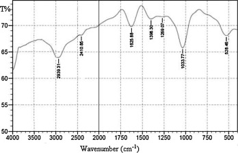
Fig. 1 shows the FTIR spectrum of PMA. Two absorption bands are observed at 1625 cm−1 and 1269 cm−1, corresponding to the carbonyl (C
O) group [17]. The peaks in the region ∼2800 to 3000 cm−1 are associated with the methylene (
CH2
) and (
C
H) group[18]. The C
O absorption bands in the ester group of PMA are centered at 1398 and 1034 cm−1[19].
|
|
|
Figure 1. FTIR spectrum of the prepared PMA. |
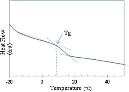
The DSC measurement is carried out on the raw PMA material and is shown in Fig. 2 and Tg is estimated from the step change of the curve. It is found that, PMA has a low glass transition temperature (Tg) of 9 °C (estimated from the step change of the curve) [12].
|
|
|
Figure 2. DSC thermogram of PMA. |
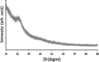
The XRD pattern of PMA is shown in Fig. 3. The PMA has only one broad peak at 2θ of about 21.14°, and is associated with a fully amorphous structure. The amorphous structure and low Tg are expected to improve the ionic conductivity of the electrolyte according to Eq. (1)[10], [20], [21], [22] and [23].
|
|
|
Figure 3. XRD of the PMA. |
3.2. Optimization of electrospinning process parameters
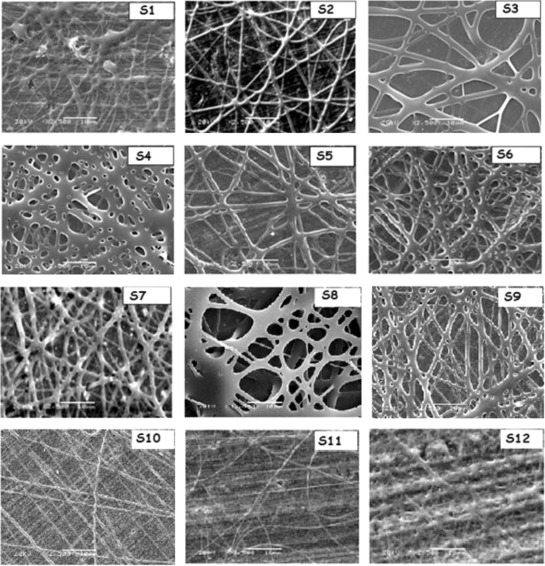
Fig. 4 shows the SEM images of all PMA samples explained in Table 1 and prepared with different electrospinning parameters. The effect of these parameters on the morphology of the membranes is explained below.
|
|
|
Figure 4. SEM images of PMA nanofibers membranes prepared with different electrospinning parameters. |
3.2.1. Polymer solution concentration
In electrospinning process, a balance among the electrostatic repulsion, surface tension, and viscoelastic force is reported to be important for controlling the fibers formation [24]. Fig. 4 shows the SEM images of the electrospun PMA membrane samples (S1–S3) using different wt% of polymer dissolved in acetone.
The instability of the jet at the spinning tip will result in significant droplets formation (8 wt%, sample S1). With an increase of the polymer concentration to 10 wt% (sample S2) in the solution, the surface tension is suppressed by the other two forces leading to uniform PMA nanofibers with average fiber diameter (AFD) of 535 nm. By increasing the polymer solution concentration to 15 wt% (sample S3), thick nanofibers with AFD of 1.2 μm are obtained. This may be due to the high resistance of the more viscous solution being stretched by the electric charges [25].
3.2.2. Applied voltage
S2, S4, and S5 samples, which presented the effect of different applied voltage on the electrospun nanofibers morphology, are shown in Fig. 4. At low applied voltage value (15 kV, sample S4), the fibers are connected with each other and form a network structure due to the elastic nature of the polymer [26] and [27]. A higher voltage is reported to induce more charges on the solution surface and fully stretch the solution jet, which yield more uniform and smooth fibers [24], so when the applied voltage increased to 20 kV (sample S2), nanofibers could be observed with AFD of 535 nm. Increasing the applied voltage to 28 kV (sample S5), results in the formation of large fibers with AFD of 820 nm. Generally, increasing the applied voltage leads to eject more fluid in the jet and thereby leads to a larger fibers diameter [26] and [28]. Therefore, uniform fibers with small average diameter can only be produced within a certain electric voltage range [29].
3.2.3. Feed rate
S2, S6, and S7 samples are prepared using different feed rates of 0.5, 1, and 2 mL/h, respectively and are shown in Fig. 4. The fibers morphology improved as feed rate decreases. It is attributed to low feed rate that allowed the solvent to have more time to evaporate, and the fibers have more time to stretch, which favored the formation of more uniform nanofibers with lower diameter [24].
3.2.4. Tip-collector distance (TCD)
In this work, the effect of TCD on the membrane morphology is studied. Different samples S8, S2, and S7 are prepared using TCD values of 7, 15 and 20 cm, respectively and are shown in Fig. 4. For short traveling distance (S8), jet is traveled to the ground collector fast due to charge attraction which leads to increase the instability of the jet yielding wet fibers. This problem is resolved by reducing the charge interaction by increasing the traveling distance to 15 cm (S2) [19]. Increasing the TCD to 20 cm (S9), the fibers are connected with each other and form a network structure as the result of reducing the charge interaction between positive charge and ground collector which reduces the elongation force [19] and [30].
3.2.5. Solvent
The change in the solvent from acetone to acetone: DMF with different volume ratios of 7:3, 6:4, and 4:6 (Fig. 4, S2, S10, S11, and S12, respectively) has great effect on the membrane morphology compared with other parameters. For PMA dissolved in acetone, large fibers diameters are formed with some small beads (S2). By adding an amount of DMF to Ac solution (S10), more uniform fibers and free beads membrane are formed.
AFD of the electrospun fiber is significantly decreased from 535 to 350 nm as the amount of DMF increased (S12, Ac:DMF is 6:4 (v/v)) due to increase of the solvent electrical conductivity (electrical conductivities for Ac and DMF are 0.02 and 1.09 mS/m respectively [31]). Also, the bending instability of the electrospinning jet increases for higher dielectric constant. This may also facilitate the reduction of the fiber diameter due to the increased jet path [32]. This is likely a result of the increased dielectric constant (ε) of the solvent due to addition of DMF (εDMF = 36.7 and () εAc = 20.7) [31] and [32]. Increasing the percentage of DMF to 6 v% in the solution, wet fibers are formed and fuse together to form a melded mat because DMF is less volatile solvent [33].
3.3. AC impedance and ionic conductivity
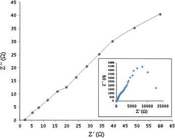
The Nyquist curve of the PMA membrane of S11 sample prepared with optimum conditions (10 wt% polymer dissolved in Ac:DMF (6:4 v/v) solution, an applied voltage of 20 kV, a feed rate of 0.5 mL/h and TCD of 15 cm) is shown in Fig. 5. In the Nyquist curve, the left intercept on z′ axis of the semi-circle represents the bulk resistance (Rb). Thus, the ionic conductivity of the polymer electrolyte can be calculated according to Eq. (3). S11 sample has the highest ionic conductivity value of 2.4 × 10⁻³ S cm−1, where this sample has the smallest and uniform fibers.
|
|
|
Figure 5. AC impedance spectrum of S11 PMA membrane sample. |
Table 2 shows the effect of using different preparation conditions on the ionic conductivity values of PMA membrane. It is concluded that, the highest value of ionic conductivity (2.4 × 10⁻³ S cm−1) is obtained for sample S11 whose electrospun process is done with the optimum conditions (10 wt% polymer dissolved in Ac:DMF (6:4 v/v) solution, an applied voltage of 20 kV, a feed rate of 0.5 mL/h and TCD of 15 cm). It may be resulted from the high porosity of the electrospun membrane and fully interconnectivity of macropores, which make the ions migrate easily and lead to increasing the membrane ionic conductivity [34].
| Sample code | Ionic conductivity (S cm−1) |
|---|---|
| S1 | 3.5 × 10⁻⁴ |
| S2 | 1.3 × 10⁻³ |
| S3 | 7.8 × 10⁻⁴ |
| S4 | 4.9 × 10⁻⁴ |
| S5 | 8.6 × 10⁻⁴ |
| S6 | 9.5 × 10⁻⁴ |
| S7 | 8.9 × 10⁻⁴ |
| S8 | 8.2 × 10⁻⁴ |
| S9 | 1.1 × 10⁻³ |
| S10 | 1.6 × 10⁻³ |
| S11 | 2.4 × 10⁻³ |
| S12 | 2.1 × 10⁻⁴ |
The bold value is the maximum ionic conductivity.
3.4. Photovoltaic performance
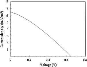
The J–V curve of the fabricated quasi-solid-state DSSC based on the electrospun PMA membrane (S11 sample) (light intensity of 100 mW cm−2) is presented in Fig. 6. The PMA membrane of S11 sample is used because this membrane has smaller AFD of 350 nm and higher ionic conductivity of 2.4 × 10⁻³ S cm−1 than another membranes. The results of Voc, Jsc, FF, and η of the DSSC device are 0.65 V, 6.5 mA cm−2, 0.32, and 1.4% under AM1.5, respectively. This cell exhibited long-term durability because of the prevention of electrolyte solution leakage.
|
|
|
Figure 6. Photocurrent voltage curve for DSSC with electrospun PMA membrane electrolyte (sample 11 in Table 2). (Light intensity: 100 mW cm−2.) |
It was expected that, all photoelectrochemical parameters are enhanced by using amorphous PMA electrospun membrane which has low Tg and high ionic conductivity as membrane for quasi-solid-state electrolyte DSSC [12], but low Jsc, FF and η values are measured compared with the values obtained by using other polymers. It is observed that, the PMA nanofibers membrane is shrinking and in contact with each other with time which leads to change the morphology and its ionic conductivity and thus impede the movement of electrolyte ions [22]. This is the possible explanation for the reduction of the cell output parameters relative to that observed in the case of the liquid electrolyte in our previous work [15].
4. Conclusion
PMA membranes have been prepared by electrospinning of the polymer solution in a mixed solvent of acetone and DMF. The effect of electrospinning parameters such as polymer concentration, applied voltage, feed rate, tip-collector distance and solvent on AFD and morphology of the membrane has been studied. A fibrous membrane with uniform morphology and an AFD of 350 nm has been prepared under the optimized electrospinning parameters of 10 wt% solution of PMA in a mixture of acetone/N,N-DMF (6:4 v/v), applied voltage of 20 kV, feed rate of 0.5 mL/h, and tip-collector distance of 15 cm. For this membrane, high ionic conductivity of 2.4 × 10⁻³ S cm−1 is exhibited at room temperature due to the easy passage of the liquid electrolyte through the fully interconnected pore structure of the membrane. The electrospun PMA membrane is employed for the first time to form quasi-solid state DSSCs. The solar to electricity conversion efficiency of quasi-solid state solar cells with the electrospun PMA electrolyte is 1.4% at an illumination intensity of 100 mW cm−2. The electrospun PMA membrane encapsulated the electrolyte solution well without leakage and displayed better long-term stability than that with conventional liquid electrolyte.
Acknowledgment
This research was supported by the Ministry of Scientific Research, Egypt, under the Science and Technology Development Fund Program (STDF), Project ID: 1414 with title “Quantum Dots Nanomaterials Dye Sensitized Solar Cells”.
References
- [1] A.R. Sathiya Priya, A. Subramania, Y.-S. Jung, K.-J. Kim; High-performance quasi-solid-state dye-sensitized solar cell based on an electrospun PVdF–HFP membrane electrolyte; Langmuir, 24 (2008), pp. 9816–9819
- [2] S. Mathew, A. Yella, P. Gao, R. Humphry-Baker, B.F.E. Curchod, N. Ashari-Astani, I. Tavernelli, U. Rothlisberger, Md.K. Nazeeruddin, M. Gratzel; Dye-sensitized solar cells with 13% efficiency achieved through the molecular engineering of porphyrin sensitizers; Nat. Chem. (2014)
- [3] J.-U. Kim, S.-H. Park, H.-J. Choi, W.-K. Lee, J.-K. Lee, M.-R. Kim; Effect of electrolyte in electrospun poly(vinylidenefluoride-co hexafluoropropylene) nanofibers on dye-sensitized solar cells; Sol. Energy Mater. Sol. Cells, 93 (2009), pp. 803–807
- [4] O.A. Ileperuma, M.A.K.L. Dissanayake, S. Somasunderam, L.R.A.K. Bandara; Photoelectrochemical solar cells with polyacrylonitrile-based and polyethylene oxide-based polymer electrolytes; Sol. Energy Mater. Sol. Cells, 84 (2004), pp. 117–124
- [5] J.Y. Kim, T.H. Kim, D.Y. Kim, N.-G. Park, K.-D. Ahn; Novel thixotropic gel electrolytes based on dicationicbis-imidazolium salts for quasi-solid-state dye-sensitized solar cells; J. Power Sources, 175 (2008), pp. 692–697
- [6] H. Moradi, Sh. Sharifnia, F. Rahimpour; Photocatalytic decolorization of reactive yellow 84 from aqueous solutions using ZnO nanoparticles supported on mineral LECA; J. Mater. Chem. Phys., 110 (2008), pp. 38–44
- [7] W. Kubo, Sh. Kambe, Sh. Nakade, T. Kitamura, K. Hanabusa, Y. Wada, Sh. Yanagida; Photocurrent-determining processes in quasi-solid-state dye-sensitized solar cells using ionic gel electrolytes; J. Phys. Chem. B, 107 (2003), pp. 4374–4381
- [8] P. Wang, S.M. Zakeeruddin, J.E. Moser, M.K. Nazeeruddin, T. Sekiguchi, M. Grätzel; A stable quasi-solid-state dye-sensitized solar cell with an amphiphilic ruthenium sensitizer and polymer gel electrolyte; Nat. Mater., 2 (2003), pp. 402–407
- [9] Z. Stoeva, I. Martin-Litas, E. Staunton, Y.G. Andreev, P.G. Bruce; Ionic conductivity in the crystalline polymer electrolytes PEO6: LiXF6, X = P, As, Sb; Am. Chem. Soc., 125 (2003), pp. 4619–4626
- [10] G.Y. Gu, S. Bouvier, C. Wu, R. Laura, M. Rzeznik, K.M. Abraham; 2-Methoxyethyl (methyl) carbonate based electrolyte for Lithium- ion batteries; Electrochim. Acta, 45 (2000), pp. 3127–3139
- [11] S.-J. Park, A.-R. Han, J.-S. Shin, S. Kim; Influence of crystallinity on ion conductivity of PEO-based solid electrolytes for lithium batteries; Macromol. Res., 18 (2010), pp. 336–340
- [12] C.W. Tu, K.Y. Liu, A.T. Chien, H. Lee, K.C. Ho, K.F. Lin; Performance of gelled-type dye-sensitized solar cells associated with glass transition temperature of the gelatinizing polymers; Eur. Polym. J., 44 (2008), pp. 608–614
- [13] A. Dey, S. Karan, A. Dey, S.K. De; Structure, morphology and ionic conductivity of solid polymer electrolyte; Mater. Res. Bull., 46 (2011), pp. 2009–2015
- [14] A.B. Kashyout, M. Fathy, M. Soliman; Studying the properties of RF sputtered nanocrystalline Tin-doped Indium oxide; Int. J. Photoenergy, 2011 (2011), Article Article ID 139374 http://dx.doi.org/10.1155/2011/139374
- [15] A.B. Kashyout, M. Soliman, M. Fathy; Effect of preparation parameters on the properties of TiO2 nanoparticles for dye sensitized solar cells; Renew. Energy, 35 (2010), pp. 2914–2920
- [16] G. Zhu, L. Pan, J. Yang, X. Liu, H. Sun, Z. Sun; Electrospun nest shaped TiO2 structures as a scattering layer for dye sensitized solar cells; J. Mater. Chem., 22 (2012), pp. 24326–24329
- [17] L. Feng, S. Li, H. Li, J. Zhai, Y. Song, L. Jiang; Super-hydrophobic surface of aligned polyacrylonitrile nanofibers”; Angew. Chem. Int. Ed., 41 (2002), pp. 1221–1223
- [18] W. Brostow, T. Datashvili, K.P. Hackenberg; Synthesis and characterization of poly(methyl acrylate) + SiO2 hybrids; e-Polymers (054) (2008)
- [19] N. Chanunpanich, B. Lee, H. Byun; A study of electrospun PVDF on PET sheet; Macromol. Res., 16 (2008), pp. 212–217
- [20] D. Saikia, C.C. Han, Y.W. Chen-Yang; Influence of polymer concentration and dyes on photovoltaic performance of dye-sensitized solar cell with P(VdF-HFP)-based gel polymer electrolyte; J. Power Sources, 185 (2008), pp. 570–576
- [21] R.S. Daries Bella, S. Karthickprabhu, A. Maheswaran, C. Amibika, G. Hirankumar, P. Devaraj; Investigation of the ionic conductivity and dielectric measurements of poly(N-vinylpyrrolidone)-sulfamic acid polymer complexes; Physica B, 458 (2015), pp. 51–57
- [22] J.H. Kim, M.-S. Kang, Y.J. Kim, J. Won, Y.S. Kang; Poly(butyl acrylate)/NaI/I2 electrolytes for dye-sensitized nanocrystalline TiO2 solar cells; Solid State Ionics, 176 (2005), pp. 579–584
- [23] Q. Xiao, Z. Li, D. Gao, H. Zhang; A novel sandwiched membrane as polymer electrolyte for application in lithium-ion battery; Membr. Sci., 326 (2009), pp. 260–264
- [24] D. Zhang, A.B. Karki, D. Rutman, D.P. Young, A. Wang, D. Cocke, T.H. Ho, Z. Guo; Electrospun polyacrylonitrile nanocomposite fibers reinforced with Fe3O4 nanoparticles: fabrication and property analysis; Polymer (2009), pp. 4189–4198
- [25] L. Ji, C. Saquing, S.A. Khan, X. Zhang; Preparation and characterization of silica nanoparticulate – polyacrylonitrile composite and porous nanofibers; Nanotechnology, 19 (2008), p. 9 ID: 085605
- [26] X. Li, G. Cheruvally, J.K. Kim, J.W. Choi, J.H. Ahn, K.W. Kim, H.J. Ahn; Polymer electrolytes based on an electrospun poly(vinylidene fluoride-co-hexafluoropropylene) membrane for lithium batteries; J. Power Sources, 167 (2007), pp. 491–498
- [27] P.K. Panda, S. Ramakrishna; Electrospinning of alumina nanofibers using different precursors; J. Mater. Sci., 42 (2007), pp. 2189–2193
- [28] S.-H. Park, D.-H. Won, H.-J. Choi, W.-P. Hwang, S. -il Jang, J.-H. Kim, S.-H. Jeong, J.-U. Kim, J.-K. Lee, M.-R. Kim; Dye-sensitized solar cells based on electrospun polymer blends as electrolytes; Sol. Energy Mater. Sol. Cells, 95 (2011), pp. 296–300
- [29] J. Zhu, S. Wei, X. Chen, A.B. Karki, D. Rutman, D.P. Young, Z. Guo; Electrospun polyimide nanocomposite fibers reinforced with core-shell Fe–FeO nanoparticles; J. Phys. Chem. B, 114 (2010), pp. 8844–8850
- [30] C.J. Buchko, L.C. Chen, Y. Shen, D.C. Martin; Processing and microstructural characterization of porous biocompatible protein polymer thin films; Polymer, 40 (1999), pp. 397–7407
- [31] S. Ramakrishna, K. Fujihara, W.E. Teo, T.C. Lim, Z. Ma; An Introduction to Electrospinning and Nanofibers; World Scientific Publishing Co. Pte. Ltd., Singapore (2005)
- [32] T. Subbiah, G.S. Bhat, R.W. Tock, S. Parameswaran, S.S. Ramkumar; Electrospinning of nanofibers; Appl. Polym. Sci., 96 (2005), pp. 557–569
- [33] A.L. Andrady; Science and Technology of Polymer Nanofibers; John Wiley & Sons Inc, New Jersey (2008)
- [34] Z. Dong, S.J. Kennedy, Y. Wu; Electrospinning materials for energy-related applications and devices; Power Sources, 196 (2011), pp. 4886–4904
Document information
Published on 12/04/17
Licence: Other
Share this document
Keywords
claim authorship
Are you one of the authors of this document?
