Abstract
Based on the commonly used indicators for speech intelligibility, this work acoustically evaluates the two largest auditoria in the Faculty of Engineering, Helwan University, Cairo, Egypt, using experimental and digital simulation techniques. Design treatments were also suggested to improve the acoustic performance of the auditoria, where the impact of these treatments was checked using the simulation as well. The models that were analysed using the CATT software were first validated utilizing the results of the field work in the unoccupied rooms. The results showed that the acoustic quality of the two auditoria are far from the optimal conditions due to their improper acoustic characteristics and the high noise levels as well. The results of improvement proposals showed that altering the ceiling shape and adding efficient absorptive materials to the rear surfaces successfully reduced the excessive reverberation time to the optimal values, increased the early reflections and eliminated the shadow zones. In addition, decreasing the noise levels by 20 dB due to improving the window insulation noticeably improved the speech intelligibility at all receivers.
Keywords
Acoustic performance ; Speech intelligibility ; Reverberation time ; Background noise level ; Lecture auditoria
1. Introduction
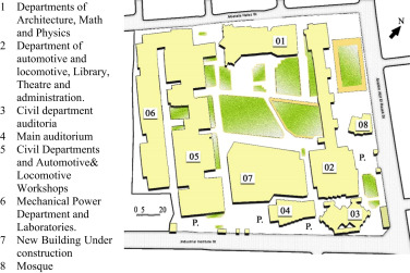
Due to frequent complaints about the low sound quality in many lecture auditoria in the Faculty of Engineering at Helwan University, particularly in large rooms, the authors have been asked by the administration of the Faculty to investigate this problem and propose feasible and economic solutions. The faculty was first established in 1955 as an industrial institute of higher education. Later, in 1975, it joined Helwan University as the Faculty of Engineering. It is located in a dense residential district to the north of Cairo City and is surrounded on three sides by narrow and congested streets. The faculty occupies approximately 12.4 acres (52.000 m2 ), shown in Figure 1 , and contains six departments. The faculty contains more than 70 auditoria of different areas and volumes; 54 of them are small rooms (less than 265 m2 ), while the rest are large rooms (more than 265 m2 ).
|
|
|
Figure 1. Layout of the Faculty of Engineering.
|
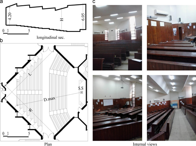
Thus, the scope of this work includes two of the large rooms in the faculty, namely, room C and the Abdolraseq room (RAZ). Room C, the second largest room in the faculty, is one of four typical lecture rooms in the department of civil engineering, building 3 in Figure 1 ; hence it represents 25% of the large auditoria in the faculty. It is a square room in which the benches have been arranged diagonally, see Figure 2 . The slope of the audience area is approximately 7о , which agrees with the minimum slope required for sight lines (Elkhateeb, 2003 ).
|
|
|
Figure 2. Typical lecture auditorium of the Civil department, room C.
|
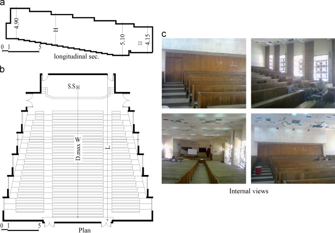
Room RAZ, the largest auditorium in the faculty, is the main lecture room for the preparatory level, Building 4 in Figure 1 . It is a trapezoidal room, as shown in Figure 3 . The slope of the audience area is approximately 9о , which provides a good sight line and grants a direct sound path for every student. Similar to most auditoria in the faculty, the two rooms utilize natural ventilation via open windows. These windows directly overlook a crowded, noisy street, parking areas and buildings 2 and 7 (see Figure 1 ). The main architectural features of both auditoria are summarised in Table 1 ; Table 2 . Speech intelligibility (SI) in lecture rooms is a major concern in educational spaces not only to support the learning process (Reich and Bradley, 1998 ) but also for lecturers’ comfort. Recent studies indicate that improper acoustic conditions in lecture rooms cause severe vocal problems for approximately one-tenth of teachers (Brunskog et al., 2009 ). Speech intelligibility is a single measure for both room acoustics and the speech-to-noise ratio (S/N) (Reich and Bradley, 1998 ); it can be governed by different indicators, such as the useful to detrimental sound ratio (U80 ), speech transmission index (STI) or its common variant, the rapid speech transmission index (RASTI) (Reich and Bradley, 1998 ; Shams and Rama krishnan, 2012 ). SI is considered to be a function of reverberation time (T); early reflection energy can increase the S/N by up to 9 dB (Bradley and Sato, 2003 ), while an S/N of +15 dB can raise SI scores by up to 100% (Bradley, 2002 ). Thus, the optimal reverberation time (Topt ) is an important criterion supporting SI (Shams and Rama krishnan, 2012 ). Background noise level (L) is another important acoustic indicator (Bradley and Sato, 2008 ); because excessive noise distracts student attention and reduces the S/N, the acceptable steady level of noise in learning spaces should not exceed 35 dB (Standard, ANSI/ASA S12.60–2010/Part1American National, 2010 ).
|
|
|
Figure 3. Main lecture auditorium, room RAZ.
|
| Dimensions | |||||||||
|---|---|---|---|---|---|---|---|---|---|
| L | W | H (avg.) | Area m2 | Volume m3 | Perm.a | D Max.b m | |||
| 16.6 | 16.6 | 5.15 | 267.8 | 1390 | 66.9 | 19 | |||
| Statistical Data | |||||||||
| No. of Audience | VP m3c | Net Audience Area m2 | APd m2 | Topt@500 Hz | Environmental Conditions | ||||
| Net | Gross | RH % | Temp. °C | ||||||
| 306 | 4.5 | 122.6 | 0.40 | 0.88 | 0.64 | 43% | 26 | ||
a. perimeter.
b. maximum distance between the sound source and farthest receiver.
c. volume per person.
d. Area per person.
| Dimensions | |||||||||
|---|---|---|---|---|---|---|---|---|---|
| L | W | H (avg.) | Area m2 | Volume m3 | Perm. | D Max. m | |||
| 23.4 | 19.4 | 4.90 | 452.2 | 2266 | 95.3 | 21.20 | |||
| Statistical Data | |||||||||
| No. of Audience | VP m3 | Net Audience Area m2 | AP m2 | Topt@500 Hz | Environmental Conditions | ||||
| Net | Gross | RH % | Temp. °C | ||||||
| 607 | 3.73 | 243 | 0.4 | 0.75 | 0.71 | 42% | 26 | ||
1.1. Related work
Many researchers have investigated the acoustics of learning spaces, either based on field measurements or digital simulation, in the design phase or after construction. DiMarino et al. DiMarino et al. (2011) analysed the acoustic performance of the proposed design for a preconstruction lecture hall in the University of Windsor׳s Centre for Engineering Innovation (CEI) using ODEON software. Four acoustic parameters were considered in this study: T, clarity (C50 ), early decay time and STI. The results indicated that both T and early decay time were less than the optimum values due to the excessive absorptive areas. Thus, upgraded materials were suggested and explored using ODEON software to enhance the acoustic quality of the room. Hodgson (Hodgson, 2004 ) investigated the acoustic performance of fourteen auditoria in the University of British Columbia before and after renovation; the values used in the evaluation of the room were estimated based on field measurements using an MLSSA system. The room verbal communication quality was quantified using the mean SI and STI. The results demonstrated that the quality of verbal communication varied from good to poor due to a renewal effect that depended on the relationship between the variation in reverberation and variation in the signal-to-noise level. Renovations often rely on using sound absorption to manage reverberation, mainly at the rear of auditoria. To determine the importance of early reflection energy on SI inside classrooms, Ellison and Germain (Ellison and Germain, 2013 ) studied the effect of an active acoustics system on controlling the early reflection energy at the Sage Hill School; this system consisted of microphones fixed throughout a room to capture the speaker׳s voice and send the signals to processors that generate early energy through loudspeakers. The results demonstrated that an active acoustic system could increase the strength and early reflection benefit while maintaining the reverberation times within acceptable limits. Elkhateeb (Elkhateeb, 2005a ; Elkhateeb, 2005b ) evaluated and analysed the acoustic environment in nine lecture auditoria in Ain Shams University, Cairo, Egypt. The work depended on field measurements for various acoustic indicators—T, centre time (TS ), C50 , definition (D50 )and L—in unoccupied rooms, except for one room that was investigated twice, occupied and unoccupied. The measured T in this room was used to validate the methodology for calculating the occupied T based on the unoccupied one. Then, the articulation loss of consonants (Alcons ) and occupied reverberation time were calculated and ray diagram analysis was performed; these were compared to their optimal values for all of the rooms under consideration. The results showed that three of the rooms had a good acoustic environment due to the suitability of their finishing materials, two rooms needed minor modifications to be good lecture rooms and the other four rooms had a poor acoustic environment due to an excessive reverberation time; finally, some modifications were suggested to mitigate those defects. Elkhateeb (Elkhateeb, 2012 ) also acoustically designed the new lecture room in the Faculty of Law at Ain Shams University, using ODEON software. After construction, the unoccupied room was evaluated by field measurements for T, D50 , STI, and L. The measured indicators were compared to the design objectives and to the values of the same indicators previously predicted by ODEON during the design phase. The results showed that the design successfully fulfilled the recommended acoustic criteria, except for L, which was relatively high due to the use of open windows for natural ventilation.
1.2. Objective
The main purpose of this work is to assess the quality of speech in two auditoria, room C and room RAZ, using field measurements and digital simulation. Based on the results of the analysis, treatments to improve the acoustic quality of the auditoria are suggested; the suitability of these treatments are verified using digital simulation.
2. Method
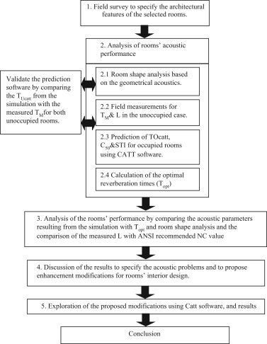
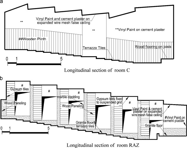
The method applied in this work to achieve the work objective is summarised in Figure 4 . For data collecting, a comprehensive architectural survey for the rooms under consideration was performed. The survey included the room dimensions, capacity and finishing materials; see Figure 5 and Table 1 ; Table 2 . The effect of the room shape on the acoustic performance was first investigated utilizing geometrical acoustics, where the distribution pattern of the acoustic rays was categorized into four zones, as shown in Table 3 (Elkhateeb, 2005a ; Elkhateeb, 2005b ).
|
|
|
Figure 4. The method.
|
|
|
|
Figure 5. The existing finishing materials of room C and room RAZ.
|
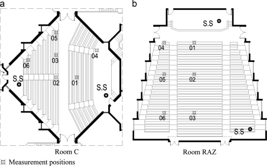
The quality of speech in the examined rooms was evaluated by four acoustic indicators: T, L, C50 and STI. In practice, field measurements for the reverberation time (TM ) and L at the octave band centre frequencies were carried out according to ISO 3382-2 (I. S. I. 3382-2, 2008 ) and ISO 1996-2 (1996-2, International Standard ISO, 2007 ), Figure 6 . The measurement tools were Brüel&Kjear instruments, including, but not limited to, a sound analyser (type 2260), an Omni sound source (type 4296) and a power amplifier to drive the sound source. The height of the microphone during the measurements was kept at 1.20 m to simulate the height of a seated student׳s ears. A total of 24 reverberation times at a source height of 1.5 m were recorded in unoccupied rooms utilizing alternating source and receiver locations. The measurements of L were carried out during class time, where all adjacent spaces were occupied with normal activities. Three discrete measurement positions were recorded in each room to cover the significant variation in noise emission. Since the windows are designed to open for ventilation, the measurements of L were performed with windows open. In addition, lighting and electrical fans were operating normally. During the measurements, the relative humidity and air temperature were monitored and recorded using a thermo-hygrometer device.
|
|
|
Figure 6. Omni source-microphone combinations in the two auditoria.
|
To estimate the effect of occupation and to calculate both C50 and STI, CATT room acoustic software version 8.0b was used. The absorption coefficients of the various surfaces used in the CATT calculations are shown in Table 4 . The properties and location of the sound source, as well as the numbers and locations of the receivers, were simulated based on those used in real measurements.
| Material | Octave band centre frequency (Hz) | |||||
|---|---|---|---|---|---|---|
| 125 | 250 | 500 | 1000 | 2000 | 4000 | |
| Ceilings | ||||||
| Vinyl paint and cement plaster on expanded wire mesh ceiling | 0.15 | 0.25 | 0.18 | 0.04 | 0.04 | 0.03 |
| 13 mm gypsum tiles over large air space | 0.2 | 0.2 | 0.2 | 0.1 | 0.05 | 0.05 |
| Walls and lining | ||||||
| Vinyl paint on cement plaster | 0.02 | 0.02 | 0.02 | 0.02 | 0.02 | 0.02 |
| 10 mm Wood panelling | 0.15 | 0.11 | 0.10 | 0.07 | 0.06 | 0.07 |
| 20 mm Marble cladding | 0.01 | 0.01 | 0.01 | 0.01 | 0.02 | 0.02 |
| 3 mm Single pane of glass | 0.08 | 0.04 | 0.03 | 0.03 | 0.02 | 0.02 |
| Solid wooden door | 0.14 | 0.10 | 0.06 | 0.08 | 0.10 | 0.10 |
| Floors | ||||||
| Terrazzo tiles | 0.02 | 0.02 | 0.02 | 0.04 | 0.05 | 0.05 |
| Granite floor | 0.05 | 0.05 | 0.05 | 0.05 | 0.05 | 0.05 |
| Wooden floor on joists | 0.15 | 0.11 | 0.10 | 0.07 | 0.06 | 0.07 |
| audience area | ||||||
| Unoccupied wooden chairs | 0.15 | 0.19 | 0.22 | 0.39 | 0.38 | 0.3 |
| Audience on wooden chairs, 2/m2 | 0.24 | 0.4 | 0.78 | 0.98 | 0.96 | 0.87 |
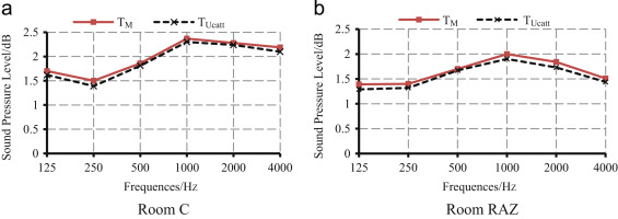
The different setups, calculation conditions and scattering coefficients used in the simulation are listed in Table 5 ; Table 6 . The results of the field measurements were used to validate the CATT model outputs. Figure 7 compares the unoccupied reverberation time obtained using CATT models (TUcatt ) and that obtained from field measurements (TM ). It can be seen that the difference between the TUcatt and TM curves is less than 10%, which is the assumed error due to differences in daily circumstances (Bradley, 2002 ). After validation, the rooms, in simulation, were considered to be occupied. The absorption coefficients (α) for the model boundaries were kept constant with respect to the unoccupied case, except for the audience (students), for which coefficients were taken according to Kuttruff (Kuttruff, 2009 ); see Table 4 . The block representing the students was given the absorption coefficients of people sitting on wooden chairs.
| Parameter | Value | Parameter | Value |
|---|---|---|---|
| Number of rays (recommended by Catt) | 21514 for room C | Background noise level | Logarithmic average of real measurements in each room. |
| 26772 for room RAZ |
| Audience | Materials with rough surfaces (e.g., gypsum boards, wood) | Glass, marble |
|---|---|---|
| 0.7 | 0.3 | 0.1 |
|
|
|
Figure 7. Comparison between TM and TUcatt for the unoccupied rooms.
|
For comparison, optimal reverberation times (Topt ) for both auditoria at 500 Hz and above were calculated according to the formula (Elkhateeb, 2005a ; Elkhateeb, 2005b ; William and Joseph, 1999 ):
|
|
( 1) |
where V is the room volume in m3 . The optimal reverberation time at frequency bands less than 500 Hz (ToptOBCF ) was calculated by applying the formula (Elkhateeb, 2005a ):
|
|
( 2) |
where n is a ratio that can be calculated from ( Elkhateeb, 2005a ):
|
|
( 3) |
where F is the centre frequency of the band. The logarithmic average of the background noise levels (Lave ) for the measured L was calculated from (South, 2004 ):
|
|
( 4) |
where x is the number of measurements.
The results of the simulation were compared to the optimal values, whereas Lave was compared to the ANSI maximum acceptable level of noise (NC-35) for educational spaces (Standard, ANSI/ASA S12.60–2010/Part1American National, 2010 ). Based on the results, the acoustic defects were specified. Accordingly, proposals to enhance and improve the acoustic quality of the two rooms were suggested. The effects of these proposals were explored using CATT software.
3. Description of the acoustic performance in the examined rooms
The acoustic performance of the rooms under consideration as well as the architectural elements that negatively affect their acoustic quality are detailed below.
3.1. Room C
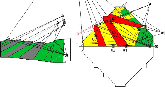
Analysis of the room shape using geometrical acoustics, as shown in Figure 8 , showed an uneven distribution of early and late reflections due to the form of the walls and ceiling. This irregularity results in the formation of many shadow zones. No flutter echoes were detected. Based on Table 3 , the room can be divided, generally, into two main zones: medium and hard acoustic zones. The first zone, medium, encompasses the front audience area, which receives early reflections from the ceiling and uneven early and late reflections from the walls. In the second zone, hard, wide strips of shadows appear due to the form of the ceiling in addition to late reflections from the rear walls. The shape of the ceiling resulted in approximately 31% of the audience area not receiving any desirable early reflections from the ceiling.
|
|
|
Figure 8. Ray diagram analysis of room C.
|
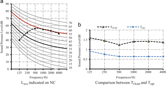
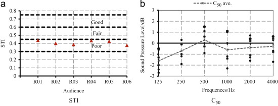
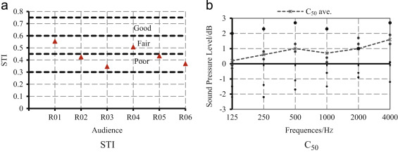
As expected, due to the noisy environment surrounding the faculty, the comparison between the measured spectrum of Lave and the maximum acceptable noise level for learning rooms (Standard, ANSI/ASA S12.60–2010/Part1American National, 2010 ), as shown in Figure 9 (a), illustrates that Lave (Nc-55) is higher than the acceptable value (Nc-35) at all frequencies. The highest noise levels, above 50 dB, occur at important frequencies for speech intelligibility (≥1 kHz). The comparison between the occupied reverberation times calculated by CATT (TOcatt ) and Topt , as shown in Figure 9 (b), indicates that there is a wide gap between the two values at all frequencies. At 1 and 2 kHz, TOcatt is more than twice Topt and is almost doubled at 500 Hz. The values of STI show that all of the receivers lay in the poor zone, as shown in Figure 10 (a), as expected due to the long reverberation time and high noise level, which reduce the S/N. The result agrees well with the analysis of the room shape; the front receivers, Nos. 1 and 4, receive the strongest direct sound, 1storder early reflections from the ceiling and 1st and 2ndorder late reflections from the rear walls. The others receive relatively abundant 1st and 2ndorder late reflections from the rear walls in addition to 1storder early reflections, either from the side walls (receivers Nos. 2, 3 and 5) or from the ceiling (receiver 6). The long reverberation time and the excessive reflections result in a very low level of clarity, as shown in Figure 10 (b), where the average values of C50 are less than 0 dB at all frequencies except 500 Hz, which has a value of 0.3 dB, because of the total power absorption at this frequency.
|
|
|
Figure 9. Noise level and reverberation time in room C.
|
|
|
|
Figure 10. STI and Clarity in room C.
|
3.2. Room RAZ
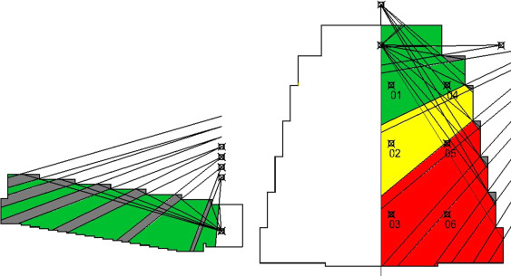
The shape of room RAZ divides it into three main zones, as shown in Figure 11 : good, medium and hard acoustic zones. The first zone, good, occupies approximately 25% of the audience area and receives strong direct sound and early sound reflections from the ceiling and walls. In the second zone, medium, almost 19% of the audience receives early reflections from the ceiling and late reflections from distant walls. In the hard zone, 56% of the audience receives late reflections from the rear walls and an uneven distribution of early reflections and many shadows from the ceiling. Again, the inappropriate shape of the ceiling resulted in approximately 22% of the audience area not receiving the desirable 1storder early reflections from the ceiling.
|
|
|
Figure 11. Ray diagram analysis of room RAZ.
|
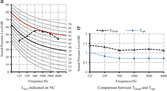
Similar to room C, the spectrum of Lave (Nc-55) is higher than the maximum acceptable level (Nc-35) at all frequencies, as shown in Figure 12 (a). The highest noise levels are at important frequencies for speech intelligibility. A comparison between TOcatt and Topt , as shown in Figure 12 (b), showed that TOcatt exceeds Topt at all frequencies; TOcatt is higher than Topt by factors of 1.6 and 1.7 at 1 and 2 kHz, respectively, and by a factor of 1.4 at 125 Hz. STI values showed that other than receivers Nos. 1 and 4, the receivers nearest to the sound source, all of the receivers lay in the poor zone, as shown in Figure 13 (a). This is expected as T and L significantly exceed the acceptable limits. The result is also compatible with the room shape analysis, in which receivers Nos. 1 and 4 receive the strongest direct field, 1storder early reflections from the ceiling and walls in addition to weak late reflections from rear surfaces. Receivers Nos. 2 and 5 receive 1storder early reflections, 1stand 2ndorder late reflections from the rear walls and no early reflections from the ceiling. Receivers Nos. 3 and 6 receive abundant late reflections from the surrounding walls in addition to 1storder early reflections from the ceiling.
|
|
|
Figure 12. Noise level and reverberation time in room RAZ.
|
|
|
|
Figure 13. STI and clarity in room RAZ.
|
The values of the C50 spectrum, as shown in Figure 13 (b), varied between 4 dB and −2.3 dB. The negative values of C50 are at receivers in the hard acoustic zone; this result is as expected due to the long T and abundant late reflections at the distant receivers.
3.3. Results and discussion
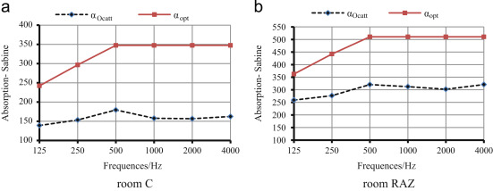
The acoustic analysis of the two rooms showed that neither fulfils the recommended criteria for learning spaces. Hence, the two auditoria are noisy and suffer from poor speech intelligibility. Although L is not more important than the acoustic design of a lecture room to achieve a satisfactory S/N ratio (Bradley and Sato, 2003 ), the high noise levels in the auditoria, 20 dB above the maximum acceptable levels, severely reduce the speech intelligibility. This noise mainly comes from the natural ventilation via the open windows that overlook a crowded, noisy street and yards for student assembly. The excessive TOcatt results from the absence of appropriate absorbing materials, although the volume per person (VP ) in both rooms is compatible with DIN-18041 (3:6 m3 /seat) (Cox and D’Antonio, 2009 ), Table 1 ; Table 2 . The volume per person in room C is higher than VP in room RAZ by a factor of 1.2, which explains why room C is acoustically worse. Moreover, the distribution and form of the reflective surfaces, especially the ceilings, are inefficient, as 31% and 25% of the audience area in Room C and RAZ, respectively, do not receive any early reflections from the ceiling (or walls, in room RAZ). These defects resulted in negative values of clarity and poor STI levels. Because early reflections and direct fields are incorporated together and perceived as one sound that is louder than the direct sound alone by 10 dB or greater (Reich and Bradley, 1998 ), the internal surfaces of the auditoria must be modified to minimize the late reflections and excessive reverberation time, maximize the desirable early reflection energy and eliminate the shadow zones. The total power of absorption in room C should be almost doubled, Figure 14 (a). For room RAZ, the total power of absorption should be increased over its recent values by a factor of 1.6 at low frequencies and 1.7 at mid and high frequencies, Figure 14 (b). The existing ceilings in both auditoria must be modified to regularly distribute the early reflections throughout the rooms.
|
|
|
Figure 14. Comparison between total room absorption for Topt and TOcatt .
|
4. Proposals for improvement
The results of the analysis show that reducing reverberation by adding more absorptive materials and eliminating the shadow zones by modifying the ceiling form will not be sufficient to improve intelligibility as long as L is very high. The classical approach to reducing L is to close the open windows, which will improve the room insulation. Such a solution imposes the use of an air conditioning system instead of natural ventilation, which is currently impractical. Therefore, different treatments were proposed and CATT software was used to corroborate the selection of the best proposal for each room as the following.
4.1. Room C
Three different proposals were suggested from which the most feasible proposal was selected.
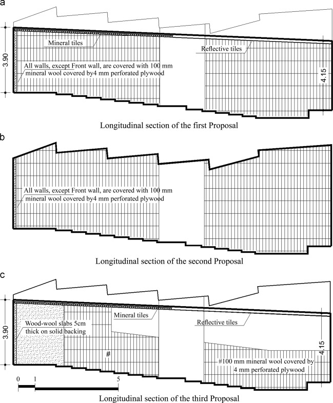
- The first proposal includes changing the form of the ceiling as well as the finishing materials for all of the internal surfaces except the front wall and floor, see Figure 15 (a) and Table 7 ; the total absorption areas are 338 m2 . The new materials include: i) covering all walls with 100 mm of mineral wool and 3 mm of perforated plywood (Kuttruff, 2009 )and ii) using reflective, painted steel tiles for the front half of the new ceiling and mineral tiles for the rear part (William and Joseph, 1999 ). The proposal also includes adding soundproof windows over the existing single pane windows to raise the sound transmission class (STC) from 28 to 54 to reduce L by 20 dB (Safelex-Acoustical Guide, 2015 ).
|
|
|
Figure 15. Proposed treatments for room C.
|
| Material | Octave band centre frequency (Hz) | |||||
|---|---|---|---|---|---|---|
| 125 | 250 | 500 | 1000 | 2000 | 4000 | |
| Ceilings | ||||||
| Reflective, painted steel tiles | 0.1 | 0.2 | 0.2 | 0.1 | 0.1 | 0.2 |
| mineral tiles | 0.3 | 0.35 | 0.4 | 0.55 | 0.8 | 0.7 |
| Walls and lining | ||||||
| 100 mm of mineral wool and 3 mm of perforated plywood | 0.7 | 0.8 | 0.75 | 0.6 | 0.5 | 0.4 |
| 50 mm thick wood-wool slabs on a solid backing | 0.2 | 0.2 | 0.6 | 0.8 | 0.7 | 0.9 |
| 50 mm mineral wool (40 kg/m3 ), glued to wall, surface sprayed with thin plastic solution | 0.15 | 0.7 | 0.6 | 0.6 | 0.75 | 0.75 |
| 20 mm Marble cladding | 0.01 | 0.01 | 0.01 | 0.01 | 0.02 | 0.02 |
| Floors | ||||||
| wooden parquet | 0.04 | 0.04 | 0.07 | 0.06 | 0.06 | 0.07 |
- The second proposal is similar to the first proposal but without any changes to the existing ceiling, as shown in Figure 15 (b). The total absorption areas are 252 m2 .
- The third proposal includes treating the back walls and half of the side walls with 50 mm thick wood-wool slabs on a solid backing, as shown in Figure 15 (c) and Table 7 , as well as treating the plinths of other walls with 100 mm of mineral wool covered by 3 mm of perforated plywood. In addition, changes to the form of the ceiling and treatment of the windows are the same as the first proposal. The total absorption areas are 269 m2 .
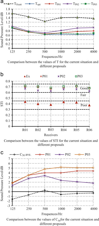
The results of the three proposals are compared with each other and with the results for the room parameters before treatments, as shown in Figure 16 . The comparison illustrates that although the third proposal covers less area by absorptive materials in comparison to the first proposal, it yields the best performance, as it is much closer to Topt at all frequencies, Figure 16 (a). This result is justified because the total absorption for the new materials in the third proposal is higher than the total absorption for the new materials in the other proposals. The new shape of the ceiling decreases the room volume by approximately 18%; nevertheless, this does not reduce VP to less than the recommended limits; it also enhances the acoustic quality within the room by eliminating the shadows. For the above-mentioned reason, the second proposal is the least effective. Due to the reduced L in the three proposals, a noticeable improvement in the intelligibility of speech was achieved at all receivers that are now located in the good zone, as shown in Figure 16 (b). Nevertheless, the third proposal again achieves the highest STI due to its optimal reverberation time. Clarity in the three proposals increased by more than 2 dB at all frequencies, as shown in Figure 16 (c). Though the third proposal yields the highest clarity, approximately 5 dB at mid and high frequencies, due to proportional correlation between C50 and T.
|
|
|
Figure 16. Effect of the different proposals on T, STI and clarity in room C.
|
4.2. Room RAZ
The following proposals were suggested to select the most feasible proposal.
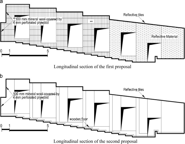
- The first proposal includes installing 100 mm of mineral wool covered with 3 mm of perforated plywood on the back and rear two-thirds of the side walls, see Figure 17 (a) and Table 7 ; using marble cladding for the front wall and the other third of the side walls; restructuring the front third of the ceiling as reflectors; and treating the windows similarly to the proposals for room C. The total absorption areas are 579 m2 .
|
|
|
Figure 17. Proposed treatments for room RAZ.
|
- The second proposal includes fixing wooden parquet to the flooring, as shown in Figure 17 (b) and Table 7 . Moreover, the windows, the ceiling shape and the back wall are treated as in the first proposal; the total absorption areas are 641 m2 .
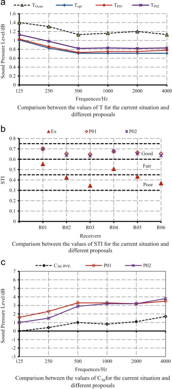
The two proposals noticeably improve the acoustic quality of the room; the first proposal yields better results despite the fact that it contains a smaller absorptive area by 10% compared to the second proposal. This result is justified for the same reasons previously mentioned in room C. In this proposal, the resulting reverberation time is too close to Topt at all frequencies, as shown in Figure 18 (a). Due to the reduction of both L and T, elimination of shadows by reshaping the ceiling and avoidance of late reflections from the rear walls, all of the receivers are now located in a good zone, as shown in Figure 18 (b). The clarity rise above 3 dB at mid and high frequencies, as shown in Figure 18 (c), reflects the enhancement of the early reflection energy and S/N accordingly.
|
|
|
Figure 18. Effect of the different proposals on T, STI and clarity in room RAZ.
|
5. Conclusions
The results of the studies performed in this research clarify that selecting the efficient absorptive materials for the rear part of ceiling and distance walls achieves the required total power of absorption, which successfully minimizes the late reflections and excessive reverberation time to the optimal value. Moreover, utilizing proper ceiling shape eliminates the shadow zones and increases the desirable early reflection energy throughout the auditoria. Although this corresponding to the optimal reverberation time and even distribution of early reflections, the negative values of clarity and poor STI cannot be avoided without decreasing the high background noise.
Based on an architectural survey, most surfaces in both rooms are reflective, which can cause an excessive reverberant sound. Shape analysis of the two rooms showed that there are many shadow zones that cover more than 20% of the audience area as a result of the ceiling shape. These shadows, in addition to the uneven distribution of the early and late reflections, divide the audience area in both rooms into medium and hard acoustic zones. The results show that TOcatt highly exceeds Topt at all frequencies; for example, TOcatt at 1 and 2 kHz is higher than Topt by more than a factor of 2 in room C and 1.5 in room RAZ. It is obvious that they are highly reverberant rooms, and room C is the worst because VP in room C is larger by 21%, although the capacity of room C is smaller than that of room RAZ by 40%. Furthermore, the measured spectra of Lave (Nc-55) in the two rooms are higher than the maximum acceptable noise level (Nc-35) by approximately 20 dB in the mid and high frequency ranges. This defect is mainly due to the intrusion of outdoor noise through the permanently open windows. Thus, good sound insulation for these windows is vital for any acoustic enhancement. In this case, natural ventilation in both rooms should be accordingly switched to a mechanical ventilation system. As a result of the excessive reverberation and the high noise levels in both rooms, the values of STI and C50 are dramatically low, excluding the receivers close to the sound source. In conclusion, the two rooms suffer from low speech intelligibility.
The analysis shows that room C requires approximately 1.9 times its current total power of absorption at low frequencies or 2.2 times at mid and high frequencies, whereas room RAZ requires approximately 1.6 times its current total power of absorption at low frequencies and 1.7 times at mid and high frequencies. To improve the acoustics within the two rooms, many scenarios have been examined. Using large area of absorptive materials to achieve the optimal reverberations time may reduce intelligibility due to reduced beneficial early reflections. Thus, the main approach is to achieve the required total power of absorption using the less area of high absorptive materials at the important frequencies for SI. The proposals also include improving the STC of the windows and reforming the shape of the ceiling, either partially or completely, to remove shadow zones. The analysis of the suggested modifications using CATT software indicates that TOcatt in both rooms becomes much closer to Topt when covering specific areas with two different highly absorptive materials. The shape of the new ceiling was designed to eliminate the shadow zones and increase the early reflections as well. In conclusion, the speech intelligibility at all receivers, as can be concluded from the new values of STI (good) and C50 (approximately 5 dB at mid and high frequency ranges).
Acknowledgments
The authors would like to thank Prof. Dr. Ahmed Abdin, Prof. of Architecture and Environmental Studies, Faculty of Engineering – Cairo University, Prof. Dr. Randa Kamel, Prof. of Architecture, Faculty of Engineering- Helwan University and Prof. Dr. Mahmoud Taha Prof. of Urban Design, Faculty of Engineering- Helwan University, for their collaboration.
References
- Bradley, 2002 J. Bradley; Optimizing Sound Quality for Classrooms; SOBRAC, Rio de Janeiro (2002)
- Bradley and Sato, 2003 J.S. Bradley, H. Sato; On the importance of early reflections for speech in rooms; J. Acoust. Soc. Am., 113 (6) (2003), pp. 3233–3244
- Bradley and Sato, 2008 J.S. Bradley, H. Sato; The intelligibility of speech in elementary school classrooms; J. Acoust. Soc. Am., 123 (4) (2008), pp. 2078–2086 http://dx.doi.org/10.1121/1.2839285
- Brunskog et al., 2009 J. Brunskog, A.C. Gade, G. Paya Bellester, L. Reig Calbo; Speaker comfort and increase of voice level in lecture rooms; J. Acoust. Soc. Am., 125 (4) (2009), pp. 2072–2082
- Cox and D’Antonio, 2009 T.J. Cox, P. D’Antonio; Acoustic Absorbers and Diffusers Theory Design and Application (2nd ed.), Spon Press (2009)
- DiMarino et al., 2011 C. DiMarino, D. Fuerth, D. Gignac, A. Lunardi, C. Novak, R. Pikul, A. Simone; Acoustic enhancement of proposed grand lecture hall using computer simulation; Can. Acoust., 39 (1) (2011), pp. 43–48
- Elkhateeb, 2003 A. Elkhateeb; Architectural Acoustics Theory and Application (1st ed.), The Anglo Egyptian Library, Cairo (2003)
- Elkhateeb, 2005a Elkhateeb, A., 2005a. Sounds In Lecture Rooms In Ain Shams University/ Acoustical Environment Assessment For The Main Auditoria, Problem Analysis and Solution Discussion- Part One: Faculty of Engineering. In: Proceedings of the 1st Ain Shams University international Conference on Environmental Engineering, ASCEE-1, Cairo.
- Elkhateeb, 2005b A. Elkhateeb; Sounds In Lecture Rooms In Ain Shams University/ Acoustical Environment Assessment For The Main Auditoria/Problem Analysis and Solution Discussion- Part Two: Faculties Of Arts, Law and Commerce; Ain Shams Eng. J. (ASEJ), 40 (4) (2005), pp. 505–541
- Elkhateeb, 2012 A. Elkhateeb; The acoustical design of the new lecture auditorium, Faculty of Law/ Ain Shams University; Ain Shams Eng. J. (ASEJ), 3 (2) (2012), pp. 219–235
- Ellison and Germain, 2013 S. Ellison, P. Germain; Optimizing Acoustics for Spoken Word Using Active Acoustics, 19, Acoustical Society of America, Canada (2013)
- Hodgson, 2004 M. Hodgson; Case-study evaluations of the acoustical designs of renovated university classrooms; Appl. Acoust., 65 (1) (2004), pp. 69–89 http://dx.doi.org/10.1016/S0003-682X(03)00108-7
- I. S. I. 3382-2, 2008 I. S. I. 3382-2; Measurement of room acoustic parameters Part 2: reverberation time in ordinary rooms; ISO, Switzerland (2008)
- Kuttruff, 2009 H. Kuttruff; Room Acoustics (5th ed.), Spon Press (2009)
- Reich and Bradley, 1998 R. Reich, J. Bradley; Optimizing classroom acoustics using computer model studies; Can. Acoust., 26 (4) (1998), pp. 15–21
- "Safelex-Acoustical Guide,", 2015 Safelex-Acoustical Guide, 2015. Saflex® . [Online].
- Shams and Rama krishnan, 2012 S. Shams, R. Rama krishnan; Acoustic metrics for classroom performance - a literature review; Can. Acoust., 40 (3) (2012), pp. 100–102
- South, 2004 T. South; Managing Noise and Vibration at Work/A Practical Guide to Assessment, Measurement and Control; Elsevier Butterworth-Heinemann, UK (2004)
- Standard, ANSI/ASA S12.60-2010/Part1American National, 2010 Standard, ANSI/ASA S12.60-2010/Part1American National; Acoustical Performance Criteria, Design Requirements and Guidelines for Schools, Part1: Permanent Schools; Acoustical Society of America, USA (2010)
- William and Joseph, 1999 J.C. William, A.W. Joseph; Architectural Acoustics: Principles and Practice; John Wiley & Sons, Inc, USA (1999)
- 1996-2, International Standard ISO, 2007 1996-2, International Standard ISO; Acoustics-Description, measurement and assessment of environmental noise, Part 2: Determination of Environmental Noise Levels; ISO, Switzerland (2007)
- 18041:2004-05, DIN, 2004 18041:2004-05, DIN; Acoustical Quality in Small to Medium-sized Rooms; Beuth Verlag GmbH, Germany (2004) (05)
Document information
Published on 12/05/17
Submitted on 12/05/17
Licence: Other
Share this document
Keywords
claim authorship
Are you one of the authors of this document?

