1 Introduction
Composites have become a relevant material in the industry due to a high performance/mass ratio. The use of high strength carbon fibers provides excellent mechanical properties to polymeric matrix while reducing thermal expansion and increasing conductivity. As a result, Carbon Fiber Reinforced Polymers (CFRP) are suitable for applications with high dimensional stability requirements such as electronic elements and aeronautical structures. Many aircraft parts, including some primary structures like wings and airframes, are made of composite materials. However, these materials present a serious handicap of being brittle and especially sensitive to impact.
During manufacturing and operation, composites structures are exposed to different impact events. Bird strikes, hailstorms or dropped tools are the main causes of failure in aeronautical structures resulting in delamination, matrix cracking, fiber-matrix interface debonding and fiber breaking. Laminates exhibit complex and varied failure mechanisms as a consequence of the anisotropic and heterogeneous nature. Moreover, the evolution of damage depends on a large set of impact parameters such as the structural laminate configuration, properties of the components (matrix and reinforcement) and physical properties of the impactor. The damage tolerance was defined by the European certification JAR 25.571 as the capability of a structure affected by corrosion, fatigue or accidental damage during the operational life to withstand reasonable loads without failure or excessive structural deformation until the damage is detected [1]. Although residual strength in impact damaged laminates can be determined through different techniques, compressive loads imply the most critical state for composite laminates that have already been subjected to impact. That is why compression after impact (CAI) tests are widely used to assess damage tolerance [2].
Even though several studies have largely focused on measuring the residual strength in composite laminates after impact, the physical mechanisms leading to the final rupture are still not completely clear today. Some authors agree that delamination created by the impact is a key factor in the final rupture owing to local buckling of the sublaminates in the area of the impact occurs under compression [3, 4]. However, recent studies have shown the importance of the impact-induced cracks in the final failure and the necessity to consider the interaction between these two damage modes [5, 6, 7, 8, 9]. Thus, buckling seems not to be the only factor driving the final rupture, but the stress concentration around the initial cracks play an important role in the propagation of the final crack.
The objective of the present paper is to study the damage scenario of CAI in order to improve the failure mechanisms knowledge. In addition, the effect of impact energy as well as thickness, stacking and scaling effects in the residual strength after impact are evaluated. For that purpose, carbon fiber epoxy resin laminates were impacted using a drop-weight tower instrument and then, compression-after-impact tests were used to measure the damage tolerance.
Even though several works on CAI tests are published, there is no universal standard for the CAI test that would state the specimen geometry and the test variables [10]. The principal requirement for a CAI device is to avoid the global buckling of the impacted specimen but instead, delaminations must progress with the local buckling of the sublaminates caused by impact. Failure mechanisms are subjected to some extent to the thickness of the composite material. The ASTM D7137/ D7137M-12 [11] standard test method proposes a CAI device for specimens with a thickness exceeding 4 mm. Nevertheless, many aeronautical structures are thinner such as horizontal tail plane, vertical tail plane (2 - 6 mm) or control surfaces (1 – 3 mm) and require an alternative method to prevent global buckling prior to the damage propagation caused by impact [12, 13]. Several anti-buckling supports designs are proposed but require changes in the specimen geometry after impact [14].
A new CAI instrument to test thin laminates is proposed in this work in order to avoid geometry modification and ensure compression failure instead of global buckling. The design of the new device and the validation process is described.
2 Experimental procedure
2.1 Materials and specimen preparation
The material used in this study is a carbon fiber/epoxy composite made of UD continuous high tensile strength carbon fibers IMA - 12 k pre-impregnated with Hexply M21E epoxy resin. The pre-impregnated tapes named as M21E/34%/UD268/IMA-12K/300/ATL were manufactured by Hexcel with the quality requirements for aeronautical applications. M21E epoxy resin exhibits an excellent damage tolerance, toughness and high performance for being used in primary aerospace structures such as those in the Airbus A350 XWB [15]. The roll was 300 mm wide and 0.262 mm thick.
The standard cure cycle recommended by Hexcel Composites Ltd. was used for these laminates. The plates were cured at 7 bar hot-pressing system together with slow heating (1-3 ºC/min), hold at 180 ºC for 120 min and followed by a cooling rate of 2-5 ºC/min. According to the ASTM 7136 [16] and ASTM 7137 [11] methods, followed for Drop-Weight Impact damage measuring and Compressive Residual Strength testing of Polymer Matrix Composites, the specimens length and width were 150 mm and 100 mm respectively. After being cured, the specimens were scanned using c-scan inspection to ensure the absence of manufacturing defects. The stacking sequences of the laminates are defined in Table 1. Thickness depends on the number of plies, therefore: 2 mm-thick for 8 plies; 3 mm-thick for 12 plies and 4 mm thick for 16 plies.
Table 1. List of the stacking sequences, number of plies and impact energy of the composite laminates used
| Stacking sequence | Nº plies | |
| Cross Ply | [(0/90)n]s | 8,12,16 |
| [0n/90n]s | 12,16 | |
| Angle Ply | [(+45/-45)n]s | 16 |
2.2 Description of the CAI device
There is no existing method of CAI applicable for specimens with all geometries and dimensions, especially thin laminates. That is why a new CAI method is presented inspired from the ASTM design with little improvements from previous studies [10,12,11]. The device proposed in this work combined several elements from previous CAI devices in order to prevent the problems in other investigations, according to the following requirements:
- Antibuckling plates are needed to test thin laminates, since critical buckling load is lower in a thin laminate than in standard thicknesses.
- The device should not interfere with the damage progression, and so the central surface of the specimen should be free.
- A rigorous positioning and alignment between the plate and the compressive load is crucial to guarantee uniaxial compression stress.
- Final failure should occur in the damage area by progression of delamination and not by compression-shear in the clamping zone, see Fig 1.
Apart from the above features, other relevant improvements are included in the design to simplify the test avoiding modifications in the geometry of the specimen.
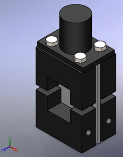
In the proposed device, an upper and a lower antibuckling plate, similar to those proposed by S. Sanchez-Saez et al. [10], are designed in order to prevent the specimen from global buckling. Both halves had a rectangular opening in the middle (50 x 26.5 mm) giving a central surface of the specimen free. The use of vertical ribs in the antibuckling plates was used to increase the specimen critical buckling load by reducing the buckling distance [12], see Fig 2.
The device was composed of a solid base where the rest of components were fitted. Although the device was designed for testing plates with the same geometry of the specimens recommended by the ASTM D7137/ D7137M-12 standard (100 mm x 150 mm), some variability in the dimension of the specimen was permitted as it is shown in Table 2.
| Table 2. Range of versatility of the CAI device in the three directions of the space. | ||
| Direction of displacement | Feature | Range |
| Z | Specimen thickness | 0-10 mm |
| Y | Compression distance | 0-10 mm |
| X | Specimen width | 0-286 mm |
The correct positioning of the specimen in the CAI device is ensured by an accurate adjustment of the components before the test in order to minimize stress concentration. The final appearance of the CAI device is shown in Fig 3.
2.3 Impact tests
The main purpose of this work was to quantify the impact damage tolerance of CFRP material. The drop-weight column CEAST 9340, with a hemispherical striker tip (∅16 mm), was used to perform the impact tests of the different laminates, see Fig 4a. Different impact energies can be induced into the specimen modifying the weights and the drop height. Thus, barely visible impact damage (BVID) or penetration was induced.
The specimens were attached in a standard impact testing fixture with an open window of 75 x 125 mm, according to the ASTM D7136/C7136M-15 standard method for measuring the damage resistance of a fiber-reinforced polymer matrix composite to a drop weight impact event (Fig 4b). Three nominal impact energies, 40 J, 50 J and 60 J, were used for the tests. Those levels of energy produced severe damages in the laminates in order to debilitate noticeably the impact area leading to compression failure in this zone and avoiding compression-shear in the clamping-zone. For that purpose, the impact energy selected in this study were: 45 J, 50 J and 60 J.
Histories of the impact load-time, impact load-displacement and impact energy-time were recorded during every test using the CEAST DAS 64k acquisition system. The damage response parameters: peak force, delamination threshold and absorbed energy, were obtained from the graphics.
2.4 Compression tests
Compression test were performed at room temperature (25ºC) and dry conditions, using an electro mechanic tensile machine EM1/100/FR with a loading cell of 100 kN and the CAI device proposed in this work. The load was applied using a screw system with double effect (tensile/compression) providing a great stability to the tests. The specimens were compressed at a constant displacement rate of 0.5 mm/min. All the data were registered during the test using the SCM3000 software of MICROTEST. The results obtained were force, deformation, position and time.
Two types of compression tests were performed in this work: Open Hole tests and compression after impact tests.
2.4.1 Open hole compressive (OHC) tests
Although this work was mainly focus on the study of the residual strength in the specimen after impact, another type of test was considered. The purpose of open hole compressive tests was not really to measure the residual strength of the plates but to highlight the role of the compressive fiber failure on the final rupture, as shown in Soutis and Curtis [17] and Rivallant et al [8]. This idea of open hole as stress concentrator was also used by Ostré et al [5]. They analyzed the failure mechanism in CFRP laminates after edge impact and concluded that compression fiber failure propagation plays a key role in the mechanism that drives the laminate residual strength.
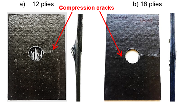
Apart from that, open hole tests were used to validate the CAI instrument proposed comparing the location of the hole and the final crack. In a proper compression test final failure should occur in the weaker section corresponding to the damage area. The residual strength obtained after impact was compared to the one obtained with a drilling hole plate. The specimens used for OHC testing were 150 mm long, 100 mm wide with 25 mm hole, see Fig 5. Two different thicknesses were considered: 12 plies and 16 plies (3 and 4 mm respectively). Both plates followed a Cross Ply stacking sequence.
2.4.2 Compression after impact (CAI) tests
CAI tests were performed in order to obtain the compression residual strength of the composite laminates after impact damage according to ASTM standards D7136 [16] and D7137 [11]. Drop-weight impacts represent real impact situations in aerospace structures such as accidental bird strikes, hailstorms or falling of a tool during maintenance or fabrication. Accidental impact damage is the main cause of failure in composite structures. In consequence, many studies about the influence of different parameters in the residual strength of the material are carrying out in order to prevent catastrophic fracture during service. In this work, the effects of impact energy, thickness, stacking sequence and ply clustering were evaluated in order to identify the parameters that affect the residual strength after impact. Moreover, the crack propagation and the strain evolution in compression direction were studied in order to provide more CAI results and clarify the mechanisms involved in the final rupture.
3 Results and discussion
3.1 Open hole compressive (OHC) results
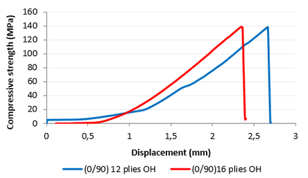
Compressive tests were carried out first to the specimens with the drilling hole. Fig. 6 shows the crack propagation and final failure in these plates due to compressive loads. The cracks were localized in the central section in both cases. High compressive stress concentration around the hole causes the fibers to micro-buckle and fracture resulting in both shear and compression deformations and initiate a kinking process, as shown by Muhammad et al. [18]. Then, successive buckling and fracture of nearby fibers form a kink band [19]. Fig. 7 displays the stress-displacement behavior of composite samples during the tests. In these curves non-linear behavior appears at the beginning of the tests corresponding to the sample positioning and should not be considered for interpretation [5]. Then, a linear increase of stress is observed until the maximum value followed by a sudden drop of stress. The initial elastic behavior and final failure is very much alike despite the different thicknesses. The ultimate open-hole compression strength was 138, 63 MPa for the OH-12 plies and 138, 53 MPa for the OH-16 plies. Nevertheless, a slight increase in the compression distance was observed for the thinner plate because of a greater flexibility, see Table 3.
| Table 3. Numeric results obtained from compression tests in OH plates | ||
| Thickness | Compression strength | Maximum position |
| 12 plies | 138, 63 MPa | 2,75 mm |
| 16 plies | 138, 53 MPa | 2,41 mm |
3.2 Compression after impact (CAI) results.
3.2.1 Impact energy effect in CAI
| Table 4. Numeric results obtained from the impact test depending on the impact energy | ||
| Impact energy | Peak Force | Absorbed energy |
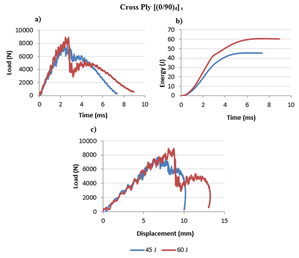
| 45 J | 7626, 1 N | 45, 2 J |
| 60 J | 8927, 9 N | 60, 3 J |
Figure 8 shows the force and energy diagrams obtained from the impact tests. Two different impact energies were selected: 45 J and 60 J. Laminates were fabricated following a cross ply stacking sequence with 12 plies. The values of peak force and absorbed energy are compared in Table 4. Higher impact energy produces more severe damage in the laminate which can be explained from a greater absorbed energy, a larger peak force and a bigger permanent deformation.
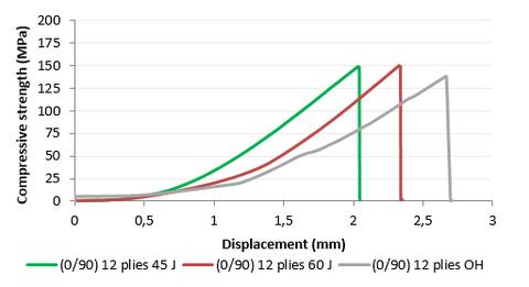
Compression tests were carried out in the laminates after impact. Fig 9 presents the stress curves as a function of the imposed displacement for two plate cases: the impacted laminates (45 J, 60 J) and the open hole plate, since they have the same thickness and stacking sequence. The maximum strength was similar for 45 and 60 J impact energy level, but open hole plate reached a slight lower strength. Rivallant et al. [8] studied the evolution of CAI stress and determined that maximum strength decreases with the impact energy and permanent indentation, but the curve trend kept almost constant near 30 J impact. It can be concluded that the reduction of strength due to impact in that range of energy is negligible.
| Table 5. Numeric results obtained from compression tests in Cross Ply – 12 plies laminates | ||
| Cross Ply – 12 plies | ||
| Impact energy | Maximum strength | Maximum displacement |
| 45 J | 148, 9 MPa | 2, 1 mm |
| 60 J | 150, 1 MPa | 2, 3 mm |
| Open Hole | 138, 7 MPa | 2, 7 mm |
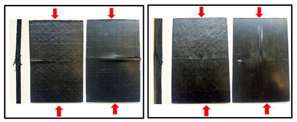
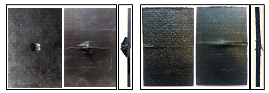
Just before the final failure, a specific broken noise is heard which indicates a possible fiber failure while the crack propagates instantaneously, as was observed by Ostré et al [5]. The final crack comes hardly at the specimen center and propagates normal to the compression direction. The physical appearance of the laminates after CAI tests are presented in Fig 10 for both impacts energies: 45 J and 60 J.
45 J 60J
3.2.2 Thickness effect in CAI
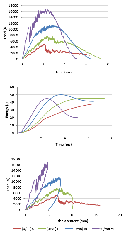
Cross Ply laminates with different thickness (2, 3, 4 and 6 mm) were tested to impact and the corresponding force and energy diagrams are presented in Figure 11. Different behaviors at the same impact energy (50 J) were observed depending on the thickness. Penetration only occurs in the thinnest laminate (8 plies), while the rest of the laminates did not absorb the total impact energy but returned part of the energy as elastic deformation. The amount of absorbed energy decreases with the thickness and consequently, the damage. Table 6 shows the values of peak force and absorbed energy obtained from the impact tests for all the laminates.
| Table 6. Numeric results obtained from the impact test depending on the laminate thickness | ||
| Nº plies | Peak Force | Absorbed energy |
| 8 | 5190, 1 N | 37,6 J |
| 12 | 7626, 1 N | 45, 2 J |
| 16 | 11410, 2 N | 41, 2 J |
| 24 | 16854, 9 N | 19, 9 J |
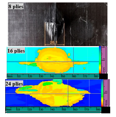
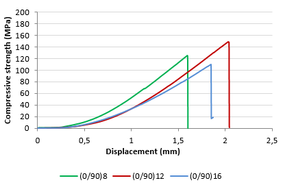
Compression after impact tests were performed in the laminates. Table 7 and Fig. 13. present the CAI results. It can be seen that the highest residual strength corresponds to the 12-plies laminate while 16 - plies laminate presents the lowest value. Firstly, the same impact energy was used for all the tests, but it was observed that 8-plies laminate presented a lower damage area and a higher dent depth in comparison to 12- plies laminates, creating a lower resistant section, see Fig 14. On the other hand, given that delamination increases with increasing the thickness (Fig. 12), a large delaminated area in 16 - plies laminate can explain the reduction in residual strength. The presence of delamination is a key factor in compression tests and causes the immediate loss of resistance in the material.
| Table 7. Numeric results obtained from compression tests in Cross Ply laminates with different thickness | ||
| Nº plies | Maximum strength | Maximum displacement |
| 8 | 124, 7 MPa | 1, 6 mm |
| 12 | 148, 9 MPa | 2, 0 mm |
| 16 | 109, 4 MPa | 1, 9 mm |
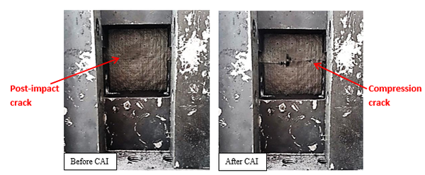
Apart from delamination, post-impact cracks appear in the upper plies of the laminate as was observed by Rivallant et al [8], and its propagation during the compression results in the final compression crack, see Fig. 15.
3.2.3 Stacking sequence effect in CAI
| Table 8. Numeric results obtained from the impact tests for different stacking sequences | ||
| Stacking sequence | Peak Force | Absorbed energy |
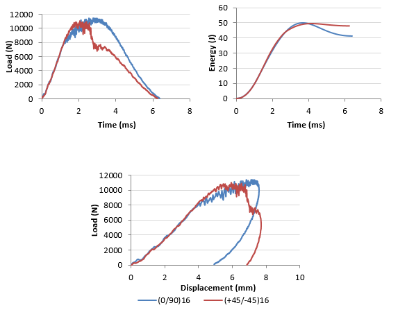
| Cross Ply | 11410, 2 N | 41, 2 J |
| Angle Ply | 11057, 3 N | 48, 1 J |
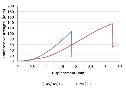
Cross Ply and Angle Ply laminates were used to study the effect of stacking sequence in the residual strength of composite material. Similar behavior was observed in the curves after impact tests: peak force and absorbed energy reached close values, see Fig 16 and Table 8.
The compression test results are summarized in Table 9, and typical curves of compressive strength-displacement response are shown in Fig. 17. The difference in the compressive behavior between the two different configurations demonstrated that the layup had a significant effect at the failure process. The presence of angle plies increased the failure strength approximately 19 %. Mili and Necib [20] determined that stacking sequence did not affect the impact behavior of laminates but the number of 0º plies influenced the central deflection. Lee and Soutis [21] analysed the compressive performance of unidirectional and multidirectional laminates after impact. They observed that off-axis layers (45º, 90º) provide lateral support to the 0º axial plies that delay the initiation of fiber microbuckling. Having the 0º plies on the surface fiber kinking is triggered earlier causing premature failures.
| Table 9. Numeric results obtained from compression tests. Effect of stacking sequence | ||
| Stacking sequence | Maximum strength | Maximum displacement |
| Cross Ply | 109,4 MPa | 1, 9 mm |
| Angle Ply | 135, 5 MPa | 3, 3 mm |
Caminero M.A et al [22] estimated the compressive properties of different M21E/IMA laminates from previous uniaxial tensile tests following the standards, see Table 10. Angle Ply laminates show higher compressive strength compared to Cross Ply, which is in accordance with de CAI results in Fig. 17. Although fibers at 0º provide superior compressive behavior, the presence of 90º fibers in Cross Ply laminates reduce compressive strength to a large extent. Comparing the maximum strength obtained from the CAI tests (Table 9) with the non-damage estimated values (Table 10), a reduction of strength is observed in both lay-up as a consequence of the damage induced by impact. This reduction is more severe for the Angle Ply laminate, which indicates a lower damage tolerance.
| Table 10. Estimated values of compressive properties of different M21E/IMA laminates | ||
| Lay - up | (MPa) | (GPa) |
| [0]12 | 1560 – 1820 | 139.54 – 156.99 |
| [90]12 | 33.63 – 39.24 | 6.99 – 7.62 |
| [45]12 | 53.79 – 62.75 | 10.46 – 11.77 |
| [0/90]3s | 124.2 – 144.9 | 14.95 – 16.82 |
| [±45]3s | 700.8 – 812 | 69.92 – 78.66 |
| [0/90/(±45)2]s | 502.2 – 585.9 | 45.7 – 51.41 |
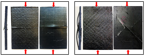
Noticeable differences can be observed in the crack propagation depending on the stacking sequence, see Fig 18. Final crack appear perpendicular to the compressive load and following fiber orientation. The crack path in the Angle Ply laminate is longer than in Cross Ply laminate which contributes to the higher compressive strength during CAI test.
3.2.4 Ply clustering effect in CAI
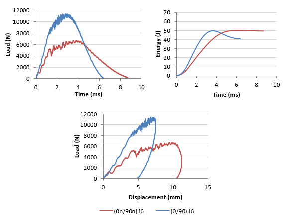
Two generic multidirectional cross ply lay ups were studied, one with blocked plies [0n/90n]s (ply level scaling) and other with distributed plies [0/90]ns (sublaminate level scaling) with n=4 in order to study the effect of ply clustering in the residual compressive strength after impact. Fig 19 shows the corresponding curves obtained from the impact tests (50 J). It was observed that lay-up affects the impact response considerably, and sublaminate laminates presented a higher impact resistance, see Table 11.
| Table 11. Numeric results obtained from the impact tests depending on the ply clustering | ||
| Ply clustering | Peak Force | Absorbed energy |
| Sublaminate [0/90]ns | 11410, 2 N | 41, 2 J |
| Ply Level [0n/90n]s | 6723, 5 N | 49, 5 J |
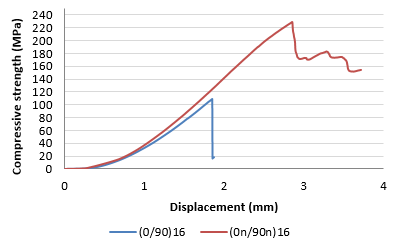
The specimens were tested to compression after impact and the typical strength-displacement curves are presented in Fig 20. Surprisingly the ultimate compressive failure of the sublaminate (109, 4 MPa) was approximately 52% lower than the strength obtained from the ply level (228, 3), see Table 12. These results are in accordance with Wisnom et al. [23] who remarked that the strength of the 4 mm ply level laminates in compression is particularly good and considerably better than for sublaminate scaled. Lee et al. [24] studied the notched compressive strength of composite laminates and concluded that compressive strength values obtained from ply-level specimens are higher than those obtained from sublaminates. They attributed these results to the stress redistribution that occurs around the hole. Local damage appears in ply level laminates at low applied compressive load which delays the final failure since stress is redistributed in the specimen and the stress concentration factor at the hole is reduced. On the contrary, sublaminates present brittle behavior and final damage occur in a catastrophic manner, resulting in a lower failure load.
| Table 12. Numeric results obtained from compression tests. Effect of ply clustering | ||
| Ply clustering | Maximum strength | Maximum displacement |
| Sublaminate [0/90]ns | 109, 4 MPa | 1,9 mm |
| Ply Level [0n/90n]s | 228, 3 MPa | 3, 9 mm |
4 Conclusions
Impact damage tolerance of carbon fiber composites was studied in order to determine the parameters influencing the ultimate compressive strength. Composite materials are very sensitive to impact damage resulting in premature failure at low compressive loads. The effect of impact energy, thickness, stacking sequence and ply clustering were evaluated through impact and compressive tests.
Open hole compressive tests were performed to validate the proposed CAI device. Stress concentration around the hole leads to final failure in the central section along the transversal direction.
No significant differences can be found in the ultimate residual strength varying the impact energy from 45 to 60 J although damage is more severe when impact energy increase. Comparing impacted specimens with Open Hole laminate, the latter reaches a lower value of compressive strength.
Fibers at 0º provide great compressive behavior but having them on the surface causes premature failure by fiber kinking. In addition, the presence of 90º fibers provokes an important drop of compressive properties. Thus, cross ply laminates (0/90)ns show lower residual strength comparing with angle ply (+45/-45)ns. However, comparing the compressive strength after impact with the non-damage estimated values, angle ply laminate suffer more severe reduction, which implies lower damage tolerance.
Although impact damage resistance is in many cases related to impact damage tolerance, it has been demonstrated that sometimes they present opposed behavior and, therefore, both effects should be considered when global impact damage is evaluated.
5 Acknowledgments
This research was supported by the Spanish Ministry of Economy and Competitiveness (National RDI Plan DPI2016-77715-R), and by University of Castilla-La Mancha (Grant no. GI20174014). I. García-Moreno also would like to acknowledge the financial support of the Castilla-La Mancha Government (JCCM) and the European Regional Developmen Fund (ERDF).
6 References
[1] Joint aviation requirements for large aeroplanes (JAR25)
[2] Richardson M. O. W, Wisheart M. J, Review of low-velocity impact properties of composite materials, Composites Part A 27 A (1996) 1123-1131
[3] Freitas MD, Reis L. Failure mechanisms on composite specimens subjected to compression after impact, Composite Structures 1998; 42(4):365–73
[4] Zhang X, Hounslow L, Grassi M, Improvement of low-velocity impact and compression-after-impact performance by z-fibre pinning, Composites Science and Technology 66 (2006) 2785-1794
[5] Ostré Benjamin, Bouvet Christophe, Minot Clément, Aboissière Jacky, Experimental analysis of CFRP laminates subjected to compression after edge impact, Composite Structures 152 (2016) 767-778
[6] Slattery P.G, McCarthy V.T, O’Higgins R.M, Assessment of residual strength of repaired solid laminate composite materials through mechanical testing, Composite Structures 147 (2016) 122-130
[7] Bouvet Christophe, Castanié Bruno, Bizeul Matthieu, Barrau Jean-Jacques, Low velocity impact modelling in laminate composite panels with discrete interface elements, International Journal of Solids and Structures, 46 (2009) 2809-2821
[8] Rivallant Samuel, Bouvet Christophe, Abi Abdallah Elias, Broll Bernhard, Barrau Jean-Jacques, Experimental analysis of CFRP laminates subjected to compression after impact: The role of impact-induced cracks in failure, Composite Structures 111 (2014) 147-157
[9] Rivallant Samuel, Bouvet Christophe, Hongkarnjanakul Natthawat, Failure analysis of CFRP laminates subjected to compression after impact: FE simulation using discrete interface elements, Composites Part A 55 (2013), 83-93
[10] Sanchez-Saez S, Barbero E, Zaera R, Navarro C, Compression after impact of thin composite laminates, Composites science and technology 65 (2005) 1911-1919
[11] ASTM 7137 (“Standard Test Method for Compressive Residual Strength Properties of Damaged Polymer Matrix Composite Plates”).
[12] Remacha M, Sánchez-Sáez S, López-Romano B, Barbero E, A new device for determining the Compression after impact strength in thin laminates, Composite Structures 127 (2015) 99-107
[13] Sebaey T.A, Mahdi E, Using thin-plies to improve the damage resistance and tolerance of aeronautical CFRP composites, Composites Part A 86 (2016) 31-38
[14] Sjöblom P, Hwang B. Compression after impact: the $5,000 data point! In: Proceedings of the 34th international SAMPE symposium, Reno, Nevada, May 8–11, 1989. p. 1411–21
[15] Resources H. Prepeg data sheets. hexply m21e epoxy matrix. product data, <www.hexcel.com>. <www.hexcel.com>.
[16] ASTM D7136 (“Measuring the Damage Resistance of a Fiber-Reinforced Polymer Matrix Composite to a Drop-Weight Impact Event”)
[17] Soutis C, Curtis PT. Prediction of the post-impact compressive strength of CFRP laminated composites. Compos Sci Technol 1996; 56: 677-84
[18] U. Saeed Muhammad, Chen ZhaoFeng, Chen ZhaoHai, Li BinBin, Compression behavior of laminated composites subjected to damage induced by low velocity impact and drilling, Elsevier, Part B 56 (2014) 815-820
[19] Gurdal Z, Haftka RT, Automated design of composite plates for improved damage tolerance. In: Composite materials: testing and design (eighth conference). Philadelphia: American Society for Testing and Materials; 1988.
[20] Mili F, Necib B. Impact behavior of cross-ply laminated composite plates under low velocities. Compos Struct 2001; 51 (3): 237-44
[21] Lee J, Soutis C, a study on the compressive strength of thick carbon fibre-epoxy laminates, Composites Science and Technology 67 (2007) 2015-2026
[22] Caminero M.A, Rodríguez G.P, Muñoz V, Effect of stacking sequence on Charpy impact and flexural damage behavior of composite laminates, Composite Structures 136 (2016) 345-357
[23] Wisnom M. R., Hallett S.R, Soutis C, Scaling effects in Notched Composites, Journal of Composite Materials OnlineFirst, 2009
[24] Lee J, Soutis C, Measuring the notched compressive strength of composite laminates: Specimen size effects, Composites Science and Technology 68 (2008) 2359- 2366
Document information
Published on 19/10/17
Accepted on 19/10/17
Submitted on 19/10/17
Volume 01 - Comunicaciones Matcomp17 (2017), Issue Núm. 1 - Comportamiento en Servicio de los Materiales Compuestos, 2017
DOI: 10.23967/r.matcomp.2017.10.008
Licence: Other
Share this document
Keywords
claim authorship
Are you one of the authors of this document?


