1 Introduction
Composite materials are suitable for a large number of lightweight structural applications, namely in transports engineering, where weight reductions, and consequently fuel efficiency, are key priorities [1]. Consequently, it is essential to pay attention to the response of these materials under extraordinary circumstances such as impacts that can affect their mechanical properties and compromise their performance. In-plane mechanical properties of composite laminates, however, are known to quickly deteriorate when subjected to out-of-plane impact loads [2,3]. There are different approaches to tackle the impact phenomenon: experimental, numerical and analytical. Although experimental and finite element approaches are still the preferred methods to study the impact behaviour of composite materials, their use is often limited by high computational costs [4]. On the other hand, analytical and theoretical approaches are good alternatives to understand the physics of the problem and provide sufficiently accurate solutions at lower computational cost than numerical methods [5]. That is why two new analytical models to predict the ballistic performance of GFRP plates are presented and a numerical model as well as experimental results are used to validate them.
2 Experimental procedure
This section aims at characterising woven E-glass fibre/polyester laminates. To this end, experimental analysis have been carried out through characterisation, non-destructive and impact tests. Different aspects such as the ballistic limit, the influence of areal density on minimum perforation velocity, the contact time, and the extension of the damaged area (front and back sides of plates) are studied.
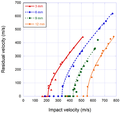
Apart from the known material properties, some others had to be obtained through the thickness direction. Therefore, friction and shear tests were carried out in order to obtain these properties. An specific tool had to be designed to perform these tests [6]. Moreover, in-plane and out-of-plane compression tests were performed. In addition, high-velocity impacts were carried out on E-glass fibre/polyester laminates. The area and the thickness of the laminates studied were 150 mm x 150 mm and 9 mm respectively. The size of the specimens is large enough so that the damaged area does not reach the border of the laminate. In order to carry out the impact tests in 9 mm thick laminates, a gas cannon manufactured by SABRE BALLISTIC (A1G+ model) was used to impulse the projectile at the required velocity. Figure 1 shows the experimental impact velocity versus residual velocity curves for the four thicknesses available. The adjustement has been set by means of the Lambert and Jonas equation:
|
|
(1) |
where is the residual velocity, is the impact velocity, is the ballistic limit and and are empirical parameters.
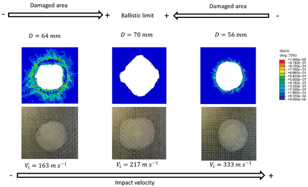
Finally, non-destructive inspection tests were carried out. The main objective of these tests is to measure the damaged area of the laminates tested in this and previous works. Relating different variables to the damaged area, it is expected to find useful relationships that help to understand better the behaviour of the laminates under high-velocity impact loads. Once the impact tests had been performed, NDI was carried out on all impacted specimens for the four thicknesses. The NDI technique used to study the damage caused by the impact was the C-Scan technique with water as coupling medium and non-contact ultrasounds. The main results are shown in Figure 2, which indicates that the maximum damaged area takes place at the ballistic limit, when the contact time is maximum.
3 Theoretical models
The energy-based theoretical models developed to predict the ballistic performance of woven E-glass/polymer laminates are presented in this section. The models assume that the kinetic energy of the projectile is partly dissipated during the perforation process and partly transferred to the composite laminate. The model hypotheses shared by the thin and thick models are the following:
- The projectile is rigid and, as such, remains undeformed during the impact.
- The laminate has linear-elastic behaviour and is x-axially symmetric (x is the thickness direction).
- Wave speeds do not change during the impact.
- The energy dissipated through tensile failure and elastic deformation of the fibres is accounted for separately.
- The energy dissipated by heat transfer is negligible.
The hypotheses that differentiate both models are the following:
- For thin laminates during penetration, the laminate moves with a different velocity from that of the projectile. Consequently, there is a relative displacement between the projectile and the laminate. This relative displacement is not taken into account for thick laminates.
- The energy dissipated by shear plugging, compression and friction is only considered in the thick laminates model.
- A plug is formed in the thick laminates model. That is why three stages are considered in contrast to the only stage considered in the thin laminates model.
The following energy-absorption mechanisms are considered for thin laminates [9]:
Due to the membrane behaviour, the laminate starts increasing its kinetic energy:
|
|
(2) |
Where , are the groups related to the laminate thickness and the laminate density, is the transverse wave radius and is the laminate velocity
The energy absorbed by elastic deformation and tensile failure of fibres, , can be expressed as the corresponding area below the in-plane stress-strain curve:
|
|
(3) |
where is the group related to the in-plane Young’s modulus of the laminate, is the in-plane strain The detailed expressions of these two mechanisms can be seen in [9].
The following energy-absorption mechanisms are considered for thick laminates [10]:
Compression of the fibres directly below the projectile, , and of the fibres sourronding the projectile, , are taken into account due to the thickness of the projectile:
|
|
(4) | |
|
|
(5) |
where , , and are the affected volume, compressive out-of-plane failure strain, compressive out-of-plane stress and compressive out-of-plane strain respectively, is an initial volume and is the volume included up to the distance travelled by the transverse wave in the in-plane direction.
To account for and add the kinetic energy from all the differentials of mass below the projectile at any time, equation (6) is defined:
|
|
(6) |
where is the velocity as a function of a mute spatial variable and time, is a differential of mass and is the mass affected by this phenomenon.
The energy-absorbed by shear plugging is defined as:
|
|
(7) |
where is the group related to the out-of-plane shear failure stress, is the projectile velocity and is the projected diameter of the projectile.
In addition to these energy-absorption mechanisms, delamination and matrix cracking are used both formulations.
The governing equation of the models are obtained by deriving the following energy balance considering or neglecting the different energy-absorption mechanisms depending on the model:
|
|
(8) |
where is the kinetic energy of the projectile at each instant of time, is the initial kinetic energy of the projectile, and are the energies absorbed by matrix cracking and delamination respectively.
A different non-linear second-order differential equation is obtained for each model. Once the initials conditions are stated, it can be solved by numerical integration:
|
(9) |
where is the acceleration of the projectile which depends on the time, the position and the velocity of the projectile and is the initial velocity of the projectile.
For the thin laminates model when the position of the projectile equals the thickness in equation (9) the residual velocity is obtained. Nevertheless, for the thick laminates model, after equation (9) a plug is formed and an instantaneous linear moment transfer is assumed in the stage two. Finally, the experimentally measured friction between the projectile and the plug formed and the laminate is the only dissipation mechanism taken into account in stage three. After this stage, the residual velocity is obtained.
4 Finite element model
To fully validate the theoretical model presented in the previous section, a 3D numerical model is developed. All the properties needed for this model can be found in [8]. This model is based on a continuum damage mechanics approach and defines the failure criteria with equivalences to the ones contemplated by the theoretical model [11-14]. The constitutive response of the material is linear-elastic up to the onset of damage and can be described in Mandel's notation as
|
|
(10) |
where and , with and , are the components of the strain tensor; , with and are the components of the stress tensor; , and are the Young's moduli, Poisson's ratios and shear moduli, with and ; and are damage parameters associated with different failure mechanisms. The evolution of the damage variables is controlled by the fracture toughness along each direction, leading to a linear decay once the onset of damage has been reached.
4.1 Failure modelling
Failure mechanisms can be either in-plane and out-of-plane. The theoretical models for thin and thick laminates presented in last section accounts for in-plane and out-of-plane energy-absorption mechanisms such as fibre breakage or compression, and each model neglects some contributions. The proposed 3D numerical model, however, includes all the energy-absorption mechanisms involved in ballistics to further validate the applicability range of the theoretical models [9,10].
In-plane tensile and compression fibre failure are triggered once the following criteria are reached [13]:
|
|
(11) | |
|
|
(12) |
where are the normal failure stresses associated with ; , , are the shear failure stresses associated with directions 12, 13 and 23 and accounts for tension and compression.
Failure by matrix cracking is assumed to be caused by in-plane shear tension according to [11], leading to
|
|
(13) |
where , , are the matrix shear failure stresses associated to directions 12, 13 and 23. This approach was also used in the model proposed by [15]. A single criterion that activates two damage variables ( and ) at the same time is defined to define through-thickness matrix and fibre failure,
|
|
(14) |
The crush failure criterion is associated to compression along the thickness of the laminate, and described by
|
|
(15) |
Finally, the interlaminar damage model used in the finite element analyses is based on the classical cohesive zone method by means of a traction-separation law [16].
4.2 FE implementation
The finite element simulations were carried out using Lagrangian 3D elements. The dimensions of the plates were the same than the experimental tests (150x150 mm2). To simulate the plates, reduced integration solid elements were used (Abaqus C3D8R). Cohesive elements were used to simulate the joint between the plies (Abaqus COH3D8). A convergence study was carried out to ensure the validity of the results. The mesh was divided in two regions, the impact zone and its surroundings, where the density of elements is higher leading to a finer mesh, and the rest, where the density of elements decay gradually as long as the region is further away from the impact zone resulting into a coarser mesh. A number of 10 and 20 solid elements were used along the thickness direction for 3 mm and 6 mm thick specimens, respectively. For the cohesive elements, 1 element (0.001 mm thick) was used along the thickness direction to simulate the joint between two plies. The projectile (density 7800 kg.m-3 and diameter 7.5 mm) was simulated as a spherical analytical surface and an exponential decay friction model was used to simulate the friction between projectile and target. Regarding the boundary conditions, the projectile was constrained to only move though the thickness direction and the exterior borders of the laminate were clamped. The elements were removed when any of the damage variables reached the value of 1. Further details of the finite element model implementation can be found in [8].
5 Results
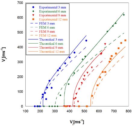
This section describes the results obtained with the theoretical models and compares these with the finite element analysis. The theoretical models are first validated with residual velocities obtained experimentally, as can be seen in Figure 3. For 3 mm and 6 mm thick specimens the model for thin laminates is used [2,9]. On the contrary, for 9 mm and 12 mm thick specimens the model for thick plates is chosen [2,10]. Figure 3 shows a good agreement between the experimental results and the models predictions.
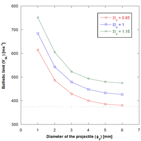
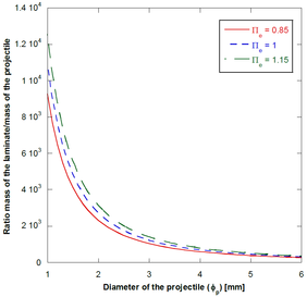
The performance of the proposed theoretical models is assessed through a number of analysis of the Π groups of the problem. One of the most important groups is the one that measures the influence of the laminate thickness and projectile diameter on the ballistic limit, , where is the projectile diameter and is the laminate thickness. The corresponding results are shown in Figure 4a for thickness-to-diameter ratios ( ) of 0.85, 1 and 1.15. As expected, the predicted ballistic limit increases with the ratio . The three cases analysed present the same behaviour. Figure 4a shows that the ballistic limit decreases when increasing the projectile diameter even though the thickness increases in the same magnitude since remains constant. Eventually, the ballistic limit tends to an asymptote in the range analysed for thin laminates. To explain these results, Figure 4b shows the projectile mass grows faster than the laminate mass. As a consequence, the projectile penetrates easier into the laminate due to the fast growth of the impactor kinetic energy. The shape of the curves shown in Figure 4 is the same suggesting that the ballistic limit is governed by the mass laminate-mass projectile ratio.
| Figure 4. Theoretical model ballistic limit predictions for different thickness-to-diameter ratios ( =0.85, =1 and =1.15) (b) Mass of the laminate / mass of the projectile ratios for different thickness-to-diameter ratios ( =0.85, =1 and =1.15) [9]. | |
Energy-absorption capacity and failure mechanisms are key factors in the design of structures and mechanical components. One of the principal advantages of the finite element model is that the failure criteria are defined with certain equivalences to the theoretical models. The intention was to be able to associate a group of failure criteria in the finite element model to a failure mode or energy-absorption mechanism in the theoretical models. In this section, the amount of energy absorbed by each mechanism is analysed. The procedure to obtain the energies follows the methodology presented by [8].
For thin laminates, the main energy-absorption mechanism observed is fibre breakage (corresponding to elastic deformation and tensile failure of fibres in the theoretical model), being even more important below the ballistic limit. Matrix cracking and delamination are proved to have a minor role in all the cases analysed despite the ballistic regime. Nevertheless, the remaining energy is dissipated mostly by through-thickness failure mechanisms, such as crushing and shear plugging, with higher influence of crushing for velocities above the ballistic limit. The influence of this mechanism is higher for 6 mm laminates since the laminate is closed to be considered as thick [2,9,10].
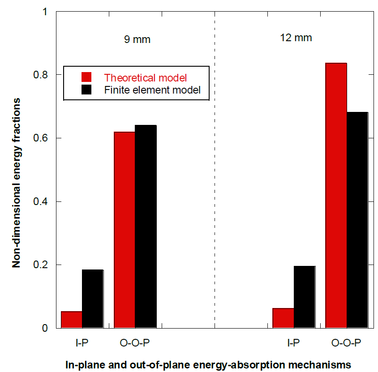
For thick laminates the major energy-absorption mechanism for both models is compression. This mechanism is followed by shear plugging in the theoretical model. The remaining energy-absorption mechanisms are minor. Overall, both the theoretical and the finite element models provide consistent results in terms of the relative roles of the energy-absorption mechanisms (see the trends shown in Figure 5). In this regard, Figure 5 shows a comparison by means of energy-absorption mechanisms grouped into in-plane and out-of-plane components for a 9 mm thick specimen impacted at 465 m.s-1 and a 12 mm thick specimen impacted at 517 m.s-1. Note that both models predict that the out-of-plane predominate over in-plane energy-absorption mechanisms.
Finally, some of the hypotheses assumed in the theoretical models such as the relative displacement for the thin model has been proven to be accurate with the FE model [9,10].
6 Conclusions
The ballistic impact of woven E-glass fibre/polyester composites was studied in this work, and two new theoretical models were proposed to describe the mechanical response and penetration of the laminates. In order to obtain different material properties needed for the models, original characterisation tests were carried out as well as high-velocity impact tests. The non-dimensional energy-based theoretical models consider traditional energy-absorption mechanisms from previous models, and incorporates new hypotheses. The main governing equation of the problem is a non-linear second-order differential equation on the position of the projectile with respect to the laminate front face in the initial configuration, which can be solved by numerical integration. In order to validate the theoretical models, the results of the ballistic limits as well as the residual velocities were compared to the experimental and the numerical model results. Agreement between theoretical model and experimental and FE results was found, with a maximum difference in the ballistic limit lower than 10%.
Different representative Π groups are studied to assess the physical consistency of the model. The most important result is that the ballistic response is governed by the laminate/projectile ratio.
The failure mechanisms in the finite element model are associated to the different energy-absorption mechanisms considered in the theoretical models. Energy-absorption mechanisms are compared between the theoretical and the FE models. For thin laminates (3 mm and 6 mm), fibre failure is identified as the most important energy-absorption mechanism while matrix cracking and delamination are proved to play a minor role. Out-of-plane failure mechanisms such as compression and shear plugging are the most dominant when analysing thick laminates (9 mm and 12 mm).
References
[() ] Llorca, J., González, C., Molina-Aldareguía, J.M., Segurado, J., Seltzer, R., Sket, F., Rodríguez, M., Sádaba, S., Muñoz, R.,
Canal, L.P., 2011. Multiscale modeling of composite materials: a roadmap towards virtual testing. Advanced Materials 23,
5130–5147. doi:10.1002/adma.201101683
[2] Alonso L, Navarro C, García-Castillo S. Experimental study of woven-laminates structures subjected to high-velocity impact. Mechanics of Advanced Materials and Structures 2018;26(12):1001–7. doi:10.1080/15376494.2018.1526354
[3] Gil-Alba, R., Alonso, L., Navarro, C., García-Castillo, S., 2019. Morphological study of damage evolution in woven-laminates subjected to high-velocity impact. Mechanics of Advanced Materials and Structures 2019, 26: 2023-26. doi:10.1080/15376494.2019.1692264.
[4] Miamí P, Camanho P, Mayugo J, Dávila C. A continuum damage model for composite laminates: Part i–constitutive model. Mechanics of Materials 2007;39(10):897–908. doi:10.1016/j.mechmat.2007.03.005.
[5] Naik N, Doshi A. Ballistic impact behaviour of thick composites: Analytical formulation. AIAA Journal 2005;43(7):1525–36. doi :10.2514/1.11993.
[6] Alonso, L., Navarro, C., García-Castillo, S., 2018a. Analytical models for the perforation of thick and thin thicknesses woven
laminates subjected to high-velocity impact. Composites Part B 143, 292–300. doi:10.1016/j.compositesb.2018.01.030.
[7] Buitrago-Pérez, B., García-Castillo, S., Barbero, E., 2010. Experimental analysis of perforation of glass/polyester structures
subjected to high-velocity impact. Material Letters 64, 1052–1054. doi:10.1016/j.matlet.2010.02.007.
[8] Alonso, L., Martínez-Hergueta, F., Garcia-Gonzalez, D., Navarro, C., García-Castillo, S., Teixeira-Dias, F., 2020. A finite
element approach to model high-velocity impact on thin woven gfrp plates. International Journal of Impact Engineering
142. doi:10.1016/j.ijimpeng.2020.103593.
[9] Alonso, L., Garcia-Gonzalez, D., Martínez-Hergueta, F., Navarro, C., Teixeira-Dias, F., García-Castillo, S., 2021a. Modeling
high velocity impact on thin woven composite plates: a non-dimensional theoretical approach. Mechanics of Advanced Materials and Structures. doi:10.1080/15376494.2021.1878402.
[10] Alonso, L., Garcia-Gonzalez, D., Navarro, C., García-Castillo, S., 2021b. A non-dimensional theoretical approach to model
high-velocity impact on thick woven plates. Steel and Composite Structures. doi:10.12989/scs.2021.38.6.000.
[11] Hashin, Z., 1980. Failure criteria for unidirectional fiber composites. Journal of Applied Mechanics 47, 329–334.
doi:10.1115/1.3153664.
[12] Muñoz, R., Martínez-Hergueta, F., Gálvez, F., González, C., Llorca, J., 2015. Ballistic performance of hybrid 3d woven
composites: experiments and simulations. Composite Structures 127, 141–151. doi: 10.1016/j.compstruct.2015.03.021.
[13] Chang, F., Chang, K., 1987. A progressive damage model for laminated composites containing stress concentrations. Journal
of Composite Materials 21, 834–855. doi:10.1177/002199838702100904.
[14] Menna, C., Asprone, D., Caprino, G., Lopresto, V., Prota, A., 2011. Numerical simulation of impact tests on gfrp composite
laminates. International Journal of Impact Engineering 38, 677–685. doi:10.1016/j.ijimpeng.2011.03.003.
[15] Xiao, J., Gama, B., Gillespie Jr, J., 2007. Progressive damage and delamination in plain weave s-2 glass/sc-15 composites
under quasi-static punch-shear loading. Composite Structures 78, 182–196. doi:10.1016/j.compstruct.2005.09.001.
[16] Turon, A., Dávila, C., Camaho, P., Coste, J., 2007. An engineering solution for mesh size effects in the simulation of delamination
using cohesive zone models. Engineering Fracture Mechanics 74, 1665–1682. doi:10.1016/j.engfracmech.2006.08.025.
Document information
Published on 13/10/21
Accepted on 06/10/21
Submitted on 20/09/21
Volume 05 - Comunicaciones Matcomp19 (2021), Issue Núm. 4 - Tesis doctorales presentadas al premio AEMAC a la mejor tesis., 2021
DOI: 10.23967/r.matcomp.2021.10.002
Licence: Other
Share this document
Keywords
claim authorship
Are you one of the authors of this document?

