1 Introducction
Due to the fact that composite materials are made with two or more constituents (polymeric resin and fibre reinforcement), the finish of the part tends to be uneven and porous. The lack of homogeneity between the constituent materials must be levelled off with the help of an external aesthetic coating with even density which will give a proper finish to the part. For this reason, many products made from composite materials require a cosmetic finishing, which can be achieved either in subsequent painting phase after demoulding the part or applying a gel-coat prior to composite process manufacturing. Consequently, the use of an in-mould coating called gel coat is a fundamental process to many long fibre composites manufacturing methods.
Gel coat serves several different functions – it provides a visually appealing glossy surface available in a wide range of colours and it protects the underlying laminate from the effects of the environment, including UV exposure, chemical attacks and water absorption. The incorporation of electrically conductive additives in the powder gel coat formulation allow the development of electrically conductive gel coat what will contribute to the growth of electrostatic plastic parts demanded in the automotive sector. In this case, the conductive powder gel coat is used as in-mould primer painting avoiding the secondary phases needed when working with plastics before applying the final coat.
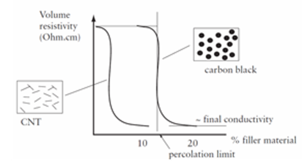
Particle size and aspect ratio are very important factors to achieve percolation at low percentages. Percolation threshold increases as the aspect ratio increases [1],[2]. The percolation limit is dependent upon the shape of the conductive particles. For traditional roughly spherical-shaped fillers at a random distribution, as carbon black, ~10–20% has to be added before the composite will be electrically conductive. The higher the aspect ratio (length-to-width ratio) of the particles, the lower is the concentration for percolation needed to take place. Carbon nanotubes (CNT) with a diameter of a few nanometres and a length of micrometres (i.e., a high aspect ratio) can form a conductive network at much lower volume fraction than cheaper, traditional fillers such as carbon black.
In this work, particles with different morphology were selected in order to study their influence on the electrical conductivity: spherical carbon black (CB) and tubular carbon nanotubes (CNT). In a first step, simulations were completed with unsatured polyester resin and carbonous particles (CNT and CB). Samples were obtained at pilot plant level and validation of simulation results was accomplished.
2 Materials and experimental
2.1 Materials
Unsatured polyester powder resins were supplied by MEGARA RESINS. Carbonous additives employed were; ENSACO 250G, supplied by TIMCAL (surface area 65 m²/g, pour Density 0,17 g/cm3) and CNT 7000, supplied by NANOCYL. (Multiwall Carbon Nanotube. Average Diameter 9.5 nanometers, aspect ratio >150). Carbonous additives were used without further treatments. A catalytic system and other additives were employed for electrically powder gel coat formulation.
2.2 Electrical percolation simulations
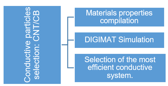
The percolation threshold of the different conductive fillers was simulated to validate the results obtained in extrusion trials. Electrical conductivity of unsaturated polyester resin was simulated with Digimat-FE software, to complete the simulation different parameters were defined such as microestructure definition, the mesh or voltage gradient. Figure 2 is a graphic representation of the methodology employed.
2.3 Preparation of electrical conductive powder gel coat
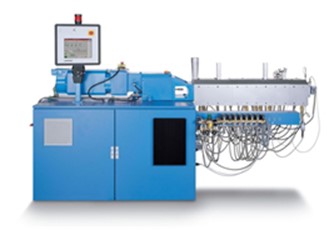
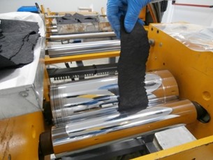
The compounding equipment used to prepare electrically conductive powder gel coat formulation was a co-rotating twin-screw extruder COPERION ZSK26 (figure 3). To feed the samples into the extruder a gravimetric dosing feeder was used and a calendar was employed to laminate the samples (figure 4).
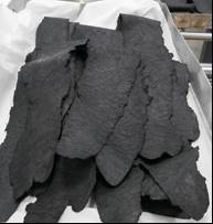
The protocol fed was defined and the screw configuration was designed to introduce separately the different components. Laminated gel coat formulation was obtained (figure 5) and prepared for grinding process.
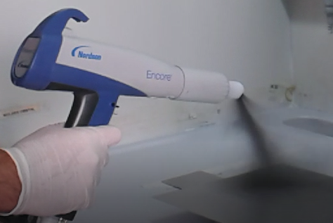
The samples were grinded with an ultra centrifugal mill (Retsch) using a 0.5 mm mesh. Afterwards the samples were sieved with an electromagnetic sieving device (CISA model RP 200N) with 1.1 mm of amplitude for 1 minute. Different sieves have been used and the fraction selected was the powder from 25 to 45 µm. This powder gel coat is ready to be applied using corona electrostatic gun (figure 6).
2.4 Characterization
2.4.1 DSC
Equipment employed to complete DSC test was Differential Scanning Calorimeter Diamond DSC from Perkin Elmer. Tg (glass transition temperature), Tc (temperature peak of the residual curing) and ΔHc (enthalpy of the residual curing) were determined for experimental samples obtained.
2.4.2 Electrical resistivity
Surface electrical conductivity was measured with a multi-meter (Keithley 2000). The resistance (Ohms) between two electrodes is measured by two point methodology and electrical resistivity is calculated taking into account the geometry of the electrodes.
Selected samples were painted with an electrospray gun onto aluminium plate in order to measure the electrical properties of the samples.
3 Results and discussions
3.1 Electrical percolation simulations
Simulation results for unsatured polyester resin with 15% of Carbon Black and unsatured polyester resin with 35% of CB are shown in figure 7 and in figure 8, respectively.
| Electrical conductivity = 10-12 S/cm |
| Geometry |
| Electrical conductivity = 10-5 S/cm |
| Geometry |
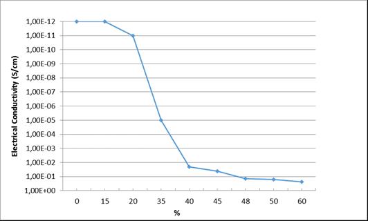
Simulation results for other percentages of CB between 15 and 60% of CB were obtained to determine percolation threshold. The conductivity values of the Digimat-FE simulation were represented versus the carbon black content in order to visually analyze the optimum carbon black content for polyester (see figure 9). The optimum carbon black content is 40% as the conductivity dramatically improves from 35% to 40%. The interconnections between carbon black particles appear at this percentage increasing the conductivity in three orders of magnitude.
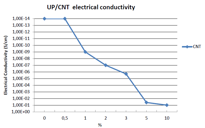
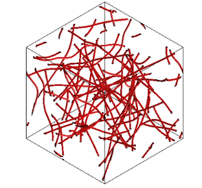
Simulation result for unsatured polyester resin and 1% of CNTs are shown in figure 10. Other percentages of CNT were also simulated obtaining results shown in figure 11.
| Electrical conductivity = 10-9 S/cm |
Geometry |
As it is shown in figure 11, percolation threshold is reduced to 3% when CNT is used as a conductive filler. According to simulation results, in order to obtain an electrical conductivity of 1E-6 S/cm (resistivity of 10+5 Ω cm) around a 3% of CNT will be needed against a 35% of CB. This result is in line with the theoretical studies that reports that CNT can form a conductive network at much lower volume fraction than traditional fillers.
3.2 Electrical percolation experimental results
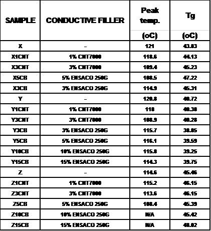
Different samples were obtained with three different types of unsatured polyester resins and two different types of carbonous fillers; CNT and CB. Due to processing problems, mainly high viscosity of the mixture, the maximum quantity of CNT that can be incorporated in the electrically conductive powder gel coat was 3% and the maximum quantity of CB was 15%. According to this, the samples obtained were represented in table 1.
Formulation with Tg value below 40 oC are rejected due to the fact that this parameter is related to storage stability and these samples will be not suitable for industrial applications. From processing point of view, formulations containing resin Y are the ones that have a better performance (viscosity, temperature during processing, laminate obtained after extrusion...).
Once extrusion laminates are obtained, the laminates were grinded and powder gel coat was applied in metallic plates to measure electrical conductivity.
As expected, only samples with a 3% of CNT shown electrical conductive properties.
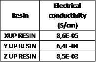
As it is illustrated in table 2 and in figure 12, values obtained differ by to two orders of magnitude. This can be explained due to processing changes according to the type of resin employed having a strong influence in final electrical path in the composite.
4 Conclusions
According to simulation results it is necessary to incorporate at least a 35% of CB in the unsatured polyester resin to obtain a good electrical path between spherical particle, obtaining good electrical properties. However, due to processing problems it is not possible to incorporate more than 15% of CB in the mixture, so no electrical properties are obtained for these laminates.
However, only with a 3% of CNT it is possible to obtain electrical conductivity values. This is in line with the results obtained in the simulation phase. The numerical model predicts a strong electrical conductivity decrease if the mass fraction is decreasing to 1%.
It is important to highlight that processing parameters have a strong influence in the formation of the electrical path inside the composite. Different electrical values are obtained depending of the type of resin employed. The three resins employed are powder unsatured polyester resins with similar Tg but there exists differences in resin viscosity. A high viscosity adversely affects the compounding processing phase increasing temperature and decreasing mixture effectivity.
Acknowledgements
The research leading to this results has received a grant from the EU (FP7/2007-2013) Seventh Framework Programme under the grant agreement no 609203.
The consortium of the project is formed by 13 European organizations that includes AIMPLAS, ECOINNOVA and CIDETEC from Spain; Composite Integration, AXON, FAR-UK, and NetComposites from United Kingdom; CLERIUM from the Netherlands, Indupol International N.V. from Belgium; e-Xstream engineering from Luxembourg; Bielefeld University (FHBI) from Germany; KETEK from Finland; Megara from Greece; and Steel Belt Systems Powder Coating Division (SBS) from Italy.
References
[1] Natsuki, T.; Endo, M.; Takahashi, T. Physica A 2005, 352, 498-508.
[2] Lu, W.; Chou, T. W.; Thostenson, E. T. Appl. Phys. Lett. 2010, 96, 223106Document information
Published on 29/04/18
Accepted on 29/04/18
Submitted on 29/04/18
Volume 02 - Comunicaciones Matcomp17 (2018), Issue Num. 2 - Aplicaciones y compuestos multifuncionales, 2018
DOI: 10.23967/r.matcomp.2018.04.012
Licence: Other
Share this document
Keywords
claim authorship
Are you one of the authors of this document?
