1 Introduction
Bonding clearly constitutes one of the best techniques for joining composites to metals or other dissimilar materials which commonly do not admit welding processes, offering higher structural integrity, corrosion resistance and sealing. However, the potential of this technique is not fully exploited if mono-adhesive solutions are considered. Failure in adhesive joints is usually driven by the non-uniform distribution of stresses or strains that generally appears along the bond-lines, with peak values near the ends of the overlaps and inner zones where the adhesive essentially does not work. For joints comprised of dissimilar materials, the stress fields are also affected by the absence of symmetry. This phenomenon is especially critical when brittle or semi-brittle structural adhesives are used, limiting the maximum load capacity of bonded joints.
In this sense, ‘functionally graded adhesive’ (FGA) or ‘multiple-adhesive’ joints are identified as powerful techniques to improve both the stresses/strains distributions and, consequently, the joints mechanical performance. In a simple way, both approaches involve the use of more flexible adhesives at the joint boundaries and more brittle/rigid ones in the center. Several studies have been conducted in this area of research in recent years: studies based on analytical formulations [1,2], numerical modeling [3–5], or a combination of the two [6–8].
This article summarize the work done by ITAINNOVA in this field within the SAFEJOINT project. Specifically, the study is focused in aluminium-composite (multidirectional glass fibre laminate – epoxy resin matrix) single lap shear (SLS) joints using epoxy adhesives. As will be described in the following section, the approach proposed by ITAINNOVA is based on mixing different compatible adhesives to be able to produce bond-lines with discrete/’banded’ properties variations, a novel strategy that can be considered as a multi-adhesive solution. The activities carried out cover the numerical analysis/ optimisation of the joints, an experimental verification through testing of SLS samples, and an example of application of the technique to solve a structural joint in a demonstrator representative of a railway sub-structure.
2 Approach
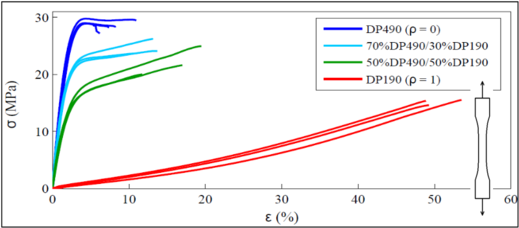
As mentioned, the grading strategy proposed is based on mixtures of two base structural adhesives: a relatively brittle one and a more flexible one. This allows adhesives with intermediate mechanical properties to be created. Then, the joints can be optimized seeking not only the best geometric parameters but also the best mechanical properties distribution. In order to be able to mix two adhesives to generate a new adhesive with tailored properties, the materials must i) be chemically compatible, ii) have enough different mechanical properties to produce significant improvement in the joints responses, and iii) be able to be polymerized using a common curing cycle (both the adhesives and their mixtures). The adhesives chosen for the study were the Scotch-Weld EPX Epoxy DP490 (brittle) and the DP190 (more flexible) from the same series (sold by 3M). Both adhesives and some mixtures created using them (50% DP490–50% DP190 and 70% DP490–30% DP190) were characterized through tensile tests. The test specimens were manufactured according to [9] with standard dimensions. Static tensile tests were conducted using a MTS Universal Testing Machine with a load cell of 100 kN at a constant cross head speed of 1.0mm/min. All tests were conducted at room temperature. The mechanical behaviour obtained in terms of the true stress and true strain for the base adhesives and different mixture ratios is plotted in Fig. 1. This graph shows how the mixture of the two adhesives effectively generates materials with resultant intermediate mechanical properties.
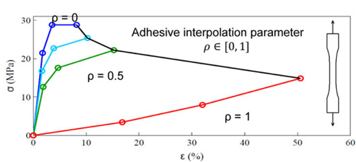
Considering the previous curves, the constitutive model used for the adhesives in the numerical studies performed (described in next section) is a tri-linear law suited for finite strains with Von Mises yield criterion and isotropic hardening. A small artificial hardening is added to the brittle adhesive in its end section in order to avoid numerical issues. The stress–strain curves ultimately used in the simulations are shown in Fig. 2. In terms of numerical implementation, a field variable (ρ) was used to introduce the material properties variation (interpolation parameter).
Schematically, the strategy presented allows manufacturing the type of bond-lines shown in figure 3.
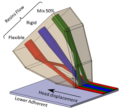
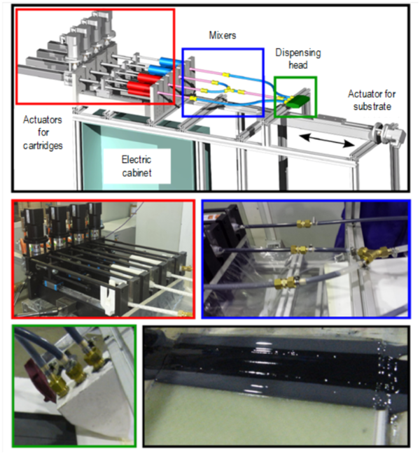
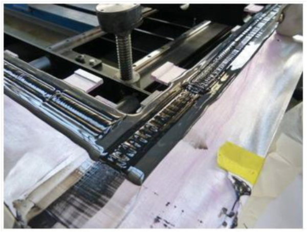
From the manufacturing point of view, these bond-lines are easier to be produced comparing with continuous gradings. In this sense, part of the work performed by ITAINNOVA in SAFEJOINT was the development of a dispensing system for the fabrication of FGA joints (Figure 4).
3 Study of discrete or ‘banded’ gradings
In order to determine the best material properties distribution along the bond-lines and the improvement potential of the technique, a 2D FE model of the single lap joints was developed under plane strain conditions. The type of elements used was CPE4 R (plain strain element, 4-node bilinear, and reduced integration), available in Abaqus Standard. There were at least 12 elements through the thickness of the adhesive layer and 7 elements in the adherents. All the simulations were performed under static considerations and with an imposed displacement. The joint model reaches its ultimate load when the first element within the adhesive layer reaches its corresponding maximum plastic strain (which depends on the position as defined by the grading of properties). This failure criterion has proved to be more adequate for flexible adhesives (like the ones considered in the present study) than those based on stresses. Taking this into account, while the improvement introduced by the grading of properties is expected to have a positive influence on all the failure modes that can appear in an adhesive joint, the failure mode considered in the FE simulations was exclusively cohesive.
The numerical study performed covers not only ‘banded’ gradings but also continuous ones. Although these gradings are difficult to manufacture, the optimum distributions are always continuous. In this sense, the goal of the “banded” or discrete approaches is basically to try to approximate as much as possible the continuous optimum solutions. Then, the objective was to obtain the most effective discrete distribution (i.e., in bands), given an optimum continuous grading. This approach is convenient because creating a search process for all the parameters that may define a “banded” grading would require a significant computational effort. More details about this study is given in [10].
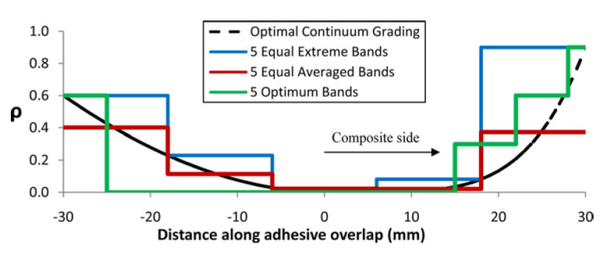
The results obtained from these analyses for a specific overlap length (60 mm) and bond-line thickness (1 mm) are shown in the next figures. The aluminium thickness considered was 2.88 mm and the thickness of the composite substrate was 2.73 mm. In Figure 7 the evolution of the maximum load with the number of bands is shown for three different discretization techniques (shown in Figure 6). The load of the continuum solution and the mono-adhesive (with the rigid adhesive) are also included as references. The asymmetry in the curves in figure 6 is associated to the consideration of dissimilar adherents.
For the case studied, the improvement predicted in terms of strength for the continuum grading (optimum solution) is near 70%. In addition, it has been seen that through an adequate configuration definition (geometry and properties) the discrete/“banded” solutions with 5 bands can offer similar improvement levels than the continuous ones.
4 Experimental verification
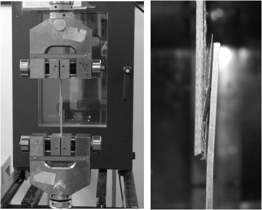
Complementing the previous analysis, the potential of the technique has been evaluated experimentally through a set of SLS tests (Figure 8)
The configuration of the samples tested is shown in Figure 9. It can be seen that the overlap length has been reduced from 60 mm to 50 mm comparing with the configuration presented in the previous section. The tests have been performed, with these dimensions, with the mono-adhesive approaches (with both the DP190 and DP490 adhesives) and with a 5 bands discrete grading. The grading has been optimized taking into account the new geometry defined (considering the optimum way of approximating the continuum grading previously obtained). The tests were conducted with a Zwick Universal Testing Machine with a load cell of 100 kN at a constant cross head speed of 0.1mm/min (to guarantee the low strain rates hypothesis), at room temperature and using a specific SLS clamping device (Figure 8).
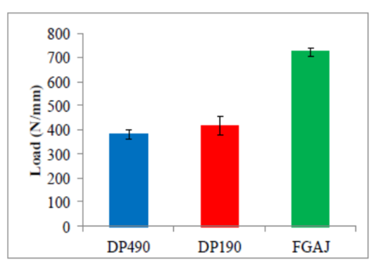
The results obtained are shown in Figure 10.
From these results, it can be seen that the improvement potential of the FGA joints is near 75 %, close to the improvements predicted by the FE simulations. However, it should be mentioned that, although it can be expected that the grading will positively influence the joint behaviour for all failure modes, the modes observed experimentally were not 100 % cohesive as it has been considered numerically.
5 Demostration - Application in a real assembly
As demonstration activity, the technology studied has been finally applied to solve a structural joint of interest for the railway sector.
The demonstrator and the tests have been defined/designed taking into account the following basic criteria:
- Section representative of a real railway structure (for example, a composite roof joined to the aluminium chassis of a metro vehicle).
- Loads representative of service conditions.
- Design of both the component and the test ensuring that the adhesive joint object of study is working as a critical structural link (i.e. the integrity of the structure depends completely on this joint).
Conceptually, the demonstrator must be useful to prove the feasibility of the techniques proposed from two points of view: i) manufacturing/execution of this type of joints and ii) mechanical/structural.
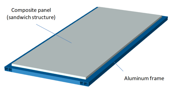
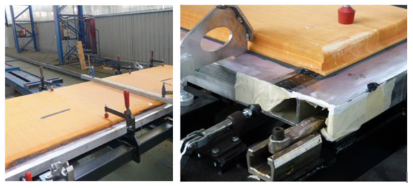
Taking into account this, the structure defined is shown in Figure 11. The ensemble is composed by a sandwich composite panel (2 mm glass fibre composite skins and a 25 mm PET core) bonded to an aluminium external frame (section with variable thicknesses between 2 mm and 6 mm). In this case, the grading has been designed specifically for the load cases of interest through a set o simulations of the full component and using sub-modelling techniques to analyse in detail different geometric and material parameters.
From the point of view of the manufacturing, the objective was mainly to check the viability of the solution for its incorporation in an industrial environment. In this sense, although the dispensing system developed within the project was initially designed to fabricate small joints samples/specimens (i.e. laboratory scale), it has been adapted to be able to fabricate larger bonded structures.
The specific objectives defined for the mechanical/structural tests were:
- Corroborate that the ‘banded’ graded bond-line makes the frame and the panel to work together until failure. In the future, this might allow incorporating the panel in the design process of the vehicle as a structural part.
- Confirm that the adhesive joint is not the weakest link in the system for the bending load case.
In terms of loads, two basic testing cases have been selected: torsion and bending. In this work only the results obtained in bending are presented.
To analyse in a comparative basis how the grading allows an effective transfer of loads from the aluminium frame to the composite panel, the following structures have been also tested:
- the aluminium structure without the composite panel, that allows to check the panel contribution in terms of stiffness.
- the composite panel bonded to the aluminium structure with a flexible adhesive (elastic PUR), a system usually used by CAF for other joints.
A brief description of the manufacturing process carried out to prepare the demonstrator is presented in section 5.1. The results obtained are presented in section 5.2.
5.1 Demonstrator manufacturing
As it has been already commented, the demonstrator has been manufactured using a dispensing system developed by ITAINNOVA within the project (Figure 12).
The whole manufacture procedure involves the following steps:
1) Design of the deposition head (depending on the ‘banded’ bond-line design).
2) Fabrication of the deposition head.
3) Calculation of the adhesives fluxes required and the velocity of the actuators.
4) Preparation of the system: cartridges, mixers, connections, tubes, etc.
5) Surface preparation of the metal substrate.
6) Surface preparation of the composite substrate - Remove of peel-ply.
7) Expel a small quantity of adhesives.
8) Application of the discrete/‘banded’ FG (functionally graded) adhesive layer.
9) Location of thickness gauges, to control the thickness of the adhesive layer.
10) Positioning of the composite substrate over the bond-lines.
11) Compaction step. Load application to close the joint until reaching the gap defined by the thickness gauges.
12) Remove the excess of adhesive.
13) Apply the curing cycle. A common cycle for the adhesives used.
Figures 13 and 14 show some of these steps.
5.2 Mechanical performance under bending
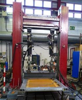
The tests have been carried out at ITAINNOVA in a testing bench using two 50KN hydraulic actuators (Intron) and measuring the displacements in different points through LVDT sensors. In addition, wire sensors have been also used to measure the displacements in the central zone during the whole test since the LVDTs sensors that were availiable do not have enough stroke. Additionally, strain gages and an acquisition system have been employed to control the strains in some specific locations. The tests have been performed until reaching the failure of the assemblies (or a high level of plastification in the case of the aluminium frame). Only one structure has been tested for each configuration (aluminium frame, aluminium frame + composite panel bonded with a standard flexible PUR adhesive, and aluminium frame + composite panel bonded with the structural ‘banded’ graded technology).
The configuration of the test is shown in the next figure.
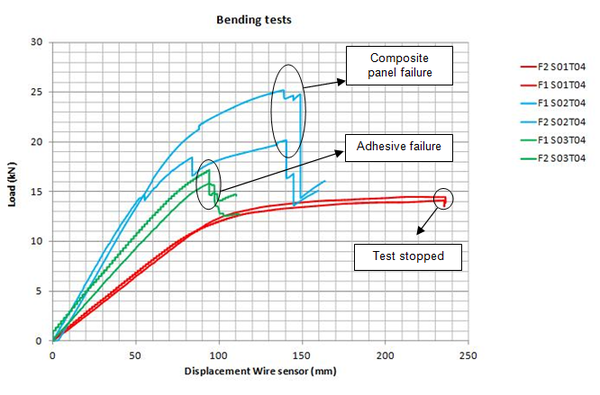
The results are plotted for each actuator (F1 and F2) separately in Figure 16.
Figure 16. Load vs. Displacement curves obtained from the bending tests. The red curves correspond to the test of the aluminium frame alone (S1). The curves in blue correspond to the demonstrator (S2, aluminium structure + the composite panel). The green curves correspond to the composite panel bonded with the flexible adhesive.
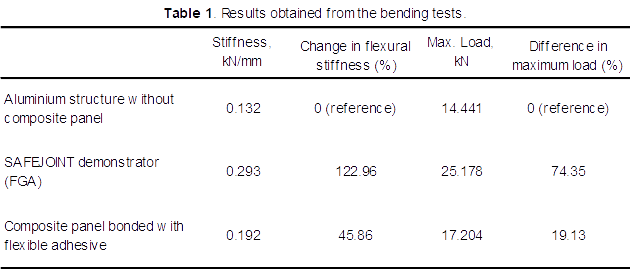
The main parameters that can be obtained from these curves (in this case, the stiffness and the maximum load) are resumed in Table 1.
It can be seen that the difference in terms of stiffness between the demonstrator (with the FGA) and the aluminium frame is approx. 123%. Moreover, the demonstrator presents also a significantly higher stiffness comparing with the panel bonded with the flexible adhesive (53% higher).
On the other hand, there is an important difference in terms of maximum loads. The demonstrator has a load capacity approx. 74 % higher than the one obtained for the aluminium frame, while the assembly with the flexible adhesive presents a load only 19% higher. Moreover, no failure/damage has been detected in the FGA, while the assembly with the flexible adhesive has started to fail due to adhesive debonding.
It can be concluded that the FGAJ makes the metallic frame and the composite panel to work together until failure in a more effective way.
In terms of failure modes, the aluminium frame alone yields but do not reach the rupture point for the maximum deflection defined for these tests. For the demonstrator manufactured with the FGA and for the panel bonded to the aluminium frame with the flexible adhesive an abrupt failure of the structures have been observed, in the first case initiated by the rupture of the composite panel (separation of one of the skins from the core) and in the second case starting with an adhesive failure in one of the corners followed again by the rupture of the composite panel.
6 Conclusions
A novel approach to produce discrete/‘banded’ graded bond-lines has been proposed based on mixing different compatible adhesives to obtain new ones with tailored mechanical properties.
Regarding the numerical study performed, the FE analysis has shown that for the case analysed the joints strength can be considerably increased through continuous variations of properties, achieving an improvement on the order of 70 % comparing with mono-adhesive solutions. Moreover, through an adequate configuration definition (geometry and properties), the discrete/‘banded’ solutions can in this case offer similar improvement levels for 5 bands – 5 adhesives. Thus, it has been clearly shown that the way in which the best continuous grading is approximated by means of bands strongly affects the level of improvement finally attained. On the other hand, the experimental tests have corroborated the improvement potential of the technique, with results close to the predicted numerically.
Finally, the feasibility of the FGAJ technique has been demonstrated both from the manufacturing and the mechanical points of view. It has been demonstrated that it is possible to manufacture discrete/’banded’ functionally graded bond-lines to join large parts using the technique proposed. Moreover, it has been seen that the process is feasible to be scaled to the industrial level. From the mechanical point of view, the FGA technique has succeeded in making the metallic frame and the composite panel to work effectively jointly until failure for a bending load case. This has been evidenced in the stiffness response of the demonstrator comparing with the one of the aluminium frame alone and the one corresponding to the structure bonded with a flexible adhesive. In addition, it has been corroborated that the FG bond-line was not the weakest link in the system since the failure was dominated by the rupture of the composite.
7 Acknowledgements
The authors wish to acknowledge the financial support received from the European Commission (FP7-NMP-2012-SMALL-6-310498 - SAFEJOINT - Enhancing structural efficiency through novel dissimilar material joining techniques) that allowed this study to be undertaken.
References
[1] Spaggiari, A. and Dragoni, E., Int. J. Adhes. Adhes. 53, 23–28 (2014).
[2] da Silva, L. F. M. and Lopes, M. J. C. Q., Int. J. Adhes. Adhes. 29, 509–514 (2009).
[3] Pires, I., Quintino, L., Durodola, J. F., and Beevers, A., Int. J. Adhes. Adhes. 23, 215–223 (2003).
[4] Boss, J. N., Ganesh, V. K., and Lim, C. T., Compos. Struct. 62, 113–121 (2003).
[5] Nimje, S. and Panigrahi, K., Int. J. Adhes. Adhes. 48, 139–149 (2014).
[6] Das Neves, P. J. C., da Silva, L. F. M., and Adams, R. D., J. Adhes. Sci. Technol. 23, 1–34 (2009).
[7] Das Neves, P. J. C., da Silva, L. F. M., and Adams, R. D., J. Adhes. Sci. Technol. 61, 35–61 (2009).
[8] Carbas, R. J. C., da Silva, L. F. M., Madureira, M. L., and Critchlow, G. W., J. Adhes. 90 (8), 698–716 (2014).
[9] ASTM D638 – 10, Standard Test Method for Tensile Properties of Plastics, ASTM International, (2010). doi:10.1520/D0638-10.
[10] R. Breto, A. Chiminelli, E. Duvivier, M. Lizaranzu & M. A. Jiménez, Journal of Adhesion, 91:12, 920-936, DOI: 10.1080/00218464.2014.976335, (2015).Document information
Published on 14/04/19
Accepted on 14/04/19
Submitted on 14/04/19
Volume 03 - Comunicaciones Matcomp17 (2019), Issue Núm. 2 - Aplicaciones, uniones y reparaciones de los materiales compuestos, 2019
DOI: 10.23967/r.matcomp.2019.04.016
Licence: Other
Share this document
Keywords
claim authorship
Are you one of the authors of this document?
