1 Introduction
A carrier or reinforcement is usually a thin fabric or paper used to support the semicured adhesive compositions, to provide a tape or film. The carrier also serves as a bond-line spacer and reinforcement for the adhesive. The use of fabric supports (carriers) in structural film adhesives has been established for some time. Such carriers are commonly glass, nylon, or polyester in woven, mat, or knitted form. Supported adhesives may be regarded as fiber-reinforced composites of low fiber volume fraction.
During heating under pressure the adhesive will tend to squeeze out from a joint. Some film adhesives contain either a lightweight fabric ‘carrier’ or microspheres which ensure an optimum minimum bondline thickness automatically. This is useful for bonding small areas to prevent excessive squeeze-out. However strength values can be slightly reduced by the presence of carriers and they can prevent the use of the reticulation technique on to honeycomb core.
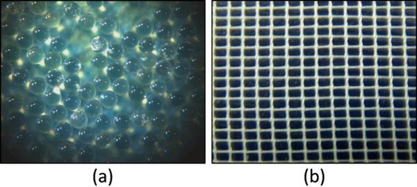
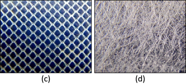
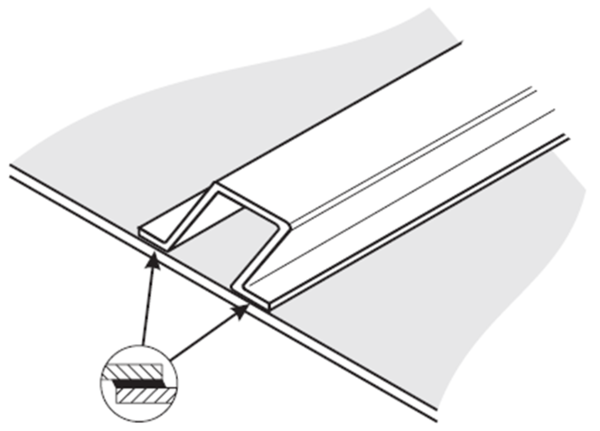
Consistent bondline thickness of the adhesive layer is critical, without uniform thickness the joint strenght is only as good as its weakest point. The control media options for thickness control are:
- Micro-Beads (mixed in the adhesive).
- Scrim Cloth.
- Knit Carriers.
- Non-woven Carriers (Mat).
2 Adhesive film bonding in composite
The adhesion are the forces or mechanisms that keep the adhesive attached to a substrate, the term refers to all adhesion mechanisms or forces located in a thin layer (boundary layer) between the substrate and the adhesive itself. The cohesion are all the forces or mechanisms that hold together the adhesive itself.
Film adhesives generally fall into 120ºC (250ºF) curing or 180ºC (350ºF) curing categories. Choice depends on equipment availability, energy economy, or service temperature requirements (usually the higher the desired operating temperature the higher the cure temperature required).
Tree types of adhesive bonding are commonly employed with composite structures. These are co-curing, co-bonding and secondary bonding.
The cocuring is the process where the prepreg and adhesives are cured simultaneously, the adhesive film is used to bond two composite adherents.
A typical co-curing application is the simultaneous cure of a stiffener and a skin. Adhesive film is frequently placed into the interface between the stiffener and the skin to increase fatigue and peel resistance. Principal advantages derived from the cocure process are excellent fit between bonded components and guaranteed surface cleanliness.
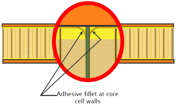
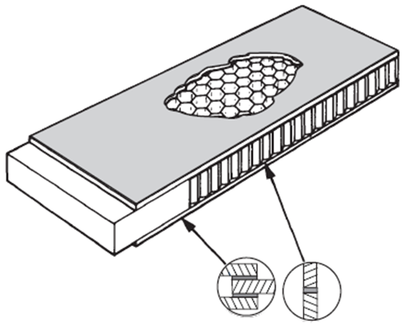
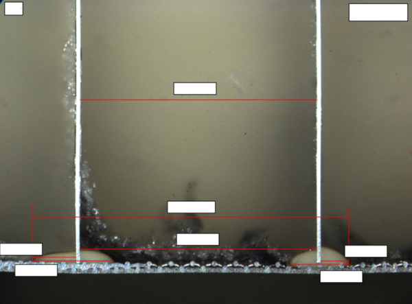
Film adhesives are used in the integration of composite, sandwich or monolithic structures. Regarding sandwich structures, the adhesive film is used to ensure a good adhesion between the core and the prepreg, through the formation of a meniscus of adhesive material in the core cell. This function is fulfilled depending on the type of "carrier". Reticulating film adhesive are also used in acoustic panels, heating an unsupported film adhesive, causing the adhesive flow away from the small holes in the acoustic skin prior to bonding into a honeycomb or other open cell core material.
For co-curing with prepregs (fibre reinforced matrix composites) to form a bonded sandwich structure, or as a ‘surface finishing’ film for prepreg, both chemical and cure cycle compatibility are essential. Compatibility with surface pretreatment protection primers and honeycomb core jointing foams is also necessary.
For Monolithic structures, the adhesive film is used to ensure a good adhesion in co-bonding processes and secondary bonding, interleaved between materials to achieve optimum thickness, guaranteeing the best mechanical properties of the element at interlaminar level.
Secondary bonding is the process where the composite semi-parts which are going to form part of the final element, are previously cured (precured) and joined in a final bonding operation by means of an adhesive.
Precured laminates undergoing secondary bonding usually have a thin nylon or fiberglass peel ply cured onto the bonding surfaces. While the peel ply sometimes hampers nondestructive inspection of the precured laminate, it has been found to be the most effective means of ensuring surface cleanliness prior to bonding. When the peel ply is stripped away, a pristine surface becomes available. Light scuff sanding removes high resin peak impressions, produced by the peel ply weave which, if they fracture, create cracks in the bondline.
Cobonding is a combination of secondary bonding and cocuring in which one detail part, usually a skin or spar web, is precured. Adhesive is placed into the bondline and additional composite plies for another detail part (e.g., a blade or hat stiffener) are laid up over the adhesive. The adhesive and composite plies are then concurrently cured together. The cobonding process has the advantage of avoiding expensive matched metal tooling that may be required for a cocured integrally stiffened composite part having the same geometry.
All of this, without forgetting, the repair processes that are within the processes of co-bonding, with all its specificities and operational limitations, either in manufacturing or in service.
3 Epoxy adhesives compatibility
Epoxy adhesives polymerize to form thermoset polymers when covalent bonds between the epoxy resin and the hardener are formed through the reaction of the epoxide ring with the ring-opening species on the hardener. Amines, amides, mercaptans, and anhydrides are some of the types of hardener that are commonly used. Catalysts can be employed to accelerate the reaction rate between the epoxy resin and hardener. In addition, heat will also accelerate the reaction. If heat is used to accelerate the cure of the epoxy, the increase in temperature can result in a drop of viscosity and an increased flow of the adhesive. Also, curing the epoxy at a higher temperature will usually result in a stiffer material with a higher crosslink density and glass transition temperature.
Compatibility characterizes the influence of different materials processed in direct contact and validates their combination in the final product. The main aspects to consider in this called compatibility characterization are chemical compatibility, physical compatibility and internal morphology & surface.
The main influencing parameters in epoxy adhesive film for composite adhesion are: mixing ratio resin/fabric, viscosity, chemical composition, resin flow, cure cycle, moisture, surface treatment, etc.
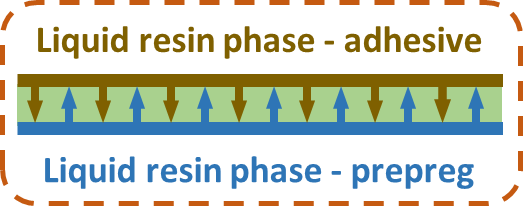
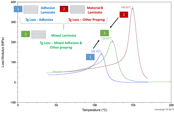
In terms of chemical compatibility, what is under study, is that the mixture of 2 or more uncured Resin Systems without basic change of material performance (Co-curing) is ocurring. One of the main tests methods in order to study and validate this chemical compatibility is the DMA (Dynamic Mechanical Analysis) test in order to obtain the Tg (glass transition temperatures) of the adhesive, the other prepreg material and both once mixed.
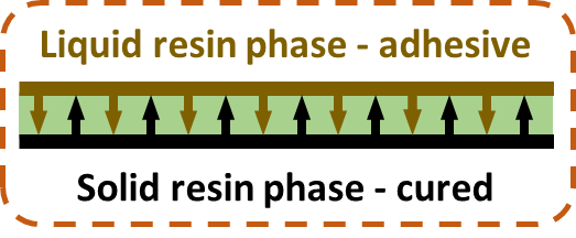
Physical compatibility is the main aspect where the selection of the adhesive carrier is a key parameter due to the high influence of this one in this compatibility. In this case, what is under study is the adhesion stability of a “solid to wet” interface not negatively impacted by e.g. surface treatment (Bonding). In order to study the physical compatibility of the adhesive in monolithic structures one of the main tests methods is the G1c Test where the mode I fracture toughness energy of bonded joints is determined. As for sandwich structures, Climbing Drum Peel & Tensile Test are two of the main tests to perform.
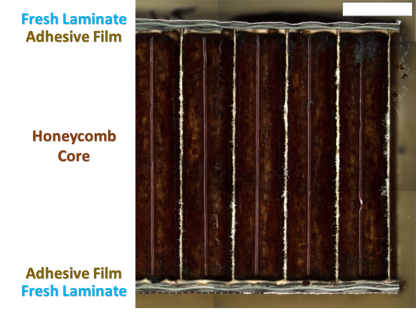
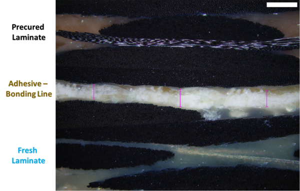
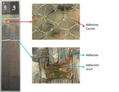
Finally, in order to study the changes of the internal morphology and surface at the interface point, specific micrographic evaluation and surface characterisations are the main aspects and tests to consider. Micrographic examples can be seen in previous figures of the document.
In cases of co-bonding and secondary bonding processes, one of the main aspects to consider is the surface pre-treatment of the cured adherent. There many methods available by mechanical o chemical processing but the use of a peel ply as surface preparation is one of the preferred and common methods.
The requirements for Compatibility are dependent on the specific bonding system, consisting of the adhesive (including carrier selection), adherend and surface pre-treatment (“Triple Combination”). Wet skin lay-up, adhesive & honeycomb for sandwich structures.
4 Adhesion in Bonded Surfaces
Polymer matrix composite adherends are considerably more affected by interlaminar shear stresses than metals, so that there is a significant need to account for such effects in stress analyses of adhesively bonded composites. Transverse shear deformations of the adherends have an effect analogous to thickening of the bond layer and result in a lowering of both shear and peel stress peaks.
Related to Physical compatibility previously mentioned, it is necessary to take a close look at the mechanical tests which are used to validate the compatibility and give us information about the quality of the adhesion in monolithic and sandwich structures.
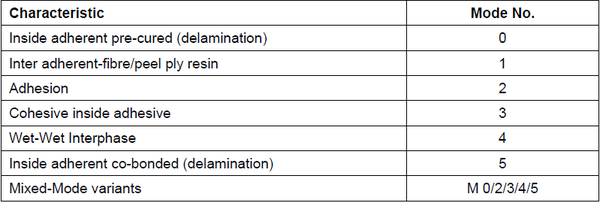
For monolithic bonding processes, in the G1c Test is very important to correctly determine the mode of failure, not only the fracture toughness energy. The mode of failure determine by means of a clasification, the location of the failure inside the elements of a bonded joint (adherent A, adhesive, adherent B and all the interfaces in between).
When removal of dry peel ply, sanding or grit blasting is used as surface pre-treatment to manufacture the panels, the classification of the location of the failure modes is as follows:
When wet peel ply removal (or any other additive layer) is used as surface pre-treatment to manufacture the panels, the classification of the location of the failure modes is as follows:
The most desired failure mode is cohesive, because avoiding failures in the interfaces or the adherents means that the adhesion, if the requirements of interlaminar fracture thoughtess are met, have been achieved. The less desired failure mode is adhesive, because this will indicate that the interface does not accomplish the necessary quality to achive the correct adhesion.
Avoidance of critical moisture uptake of the thermoset composite adherends during handling, storage and delivery before structural bonding shall be necessary to assure required bond strength and durability. The storage from the end of the cure of adherend part to the start of cure of bonding adhesive time is relevant for pre-bond moisture.
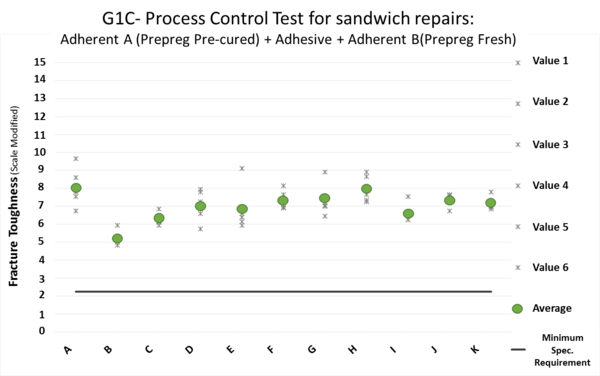
In the frame of repairs in sandwich panels G1C Test is the process control test to perform in order to validate the bonding process. A deep analysis of the adhesion in the PCS to validate the bonding process have been performed to study the robustness of the process:
- Firstly, an example from a real case of the interlaminar fracture toughness values results is shown in Figure 18.
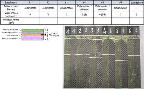
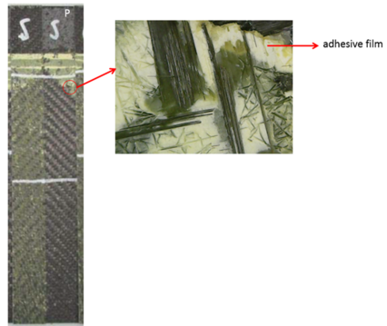
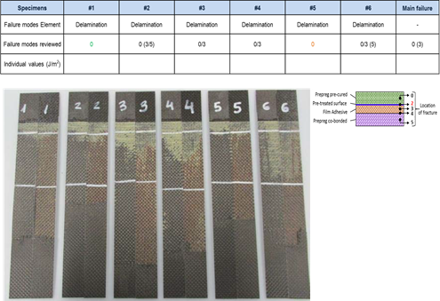
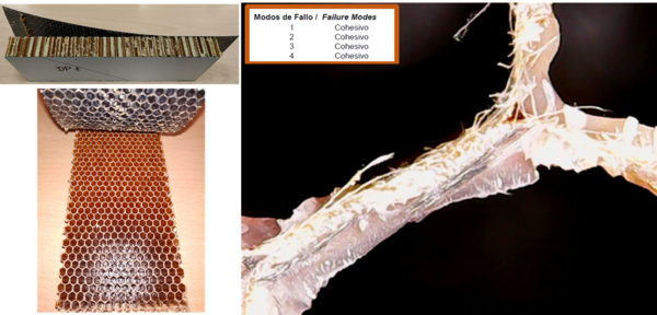
- After that, a detailed visual inspection have been perfomed in order to evaluate the mode of failure. Some of this detailed inspections are shown in the following Figures 19 & 20.
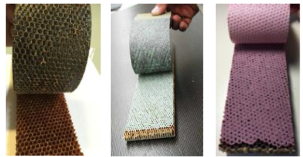
For sandwich structures is very important to evaluate also the mode of failure in the Climbing Drum Peel test and not only the DP Force performance. Visual inspection in CDP tests is not easy to read, and sometimes with mixed modes of failure requires a close visual inspection in order to stablish the mode of failure. In this case, the desired mode of failure is also cohesive; an adhesive mode of failure could mean that the carrier selected has not been a good choice.
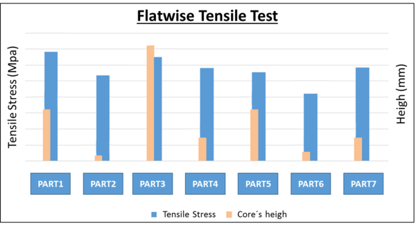
Also for sandwich structures, to interpret the tests results is very important in order to stablish if the adherence of the bonded structure is accomplished and the adhesive meniscus has been properly formed, not only the tensile stress which is highly influenced by the honeycomb core´s height and density.
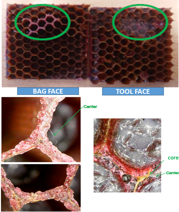
In this case, for cocuring process with honeycomb cores, the desired mode of failure is at the core. This means that the bonding line would meet its purpose and the honeycomb core would break because it is the most fragile section. Sometimes is necessary to take a closer look, when there is a combinated mode of failure as occurs in Figure 24.
In Figure 24 can be seen the pink adhesive at the bag side and tool side. The fact that the adhesive is on both sides allows to define that the mode of failure in that area of the specimen has been cohesive, the remaining area has been a failure at the core. In the tool side we can see the white resin from the adherent and rests of adhesive carrier.
5 Conclusions
Once defined all the main aspects of the adhesive bonding, focusing on the Epoxy based adhesive films for composite bonding process we will stablish the main criteria in order to define the correct choice of carriers.
It is considered that the best choice for composites sandwich structures co-curing or co-bonding (previous core stabilization process applied) processes, in order to obtain a good quality adhesive meniscus in the cell walls and consequently a good adhesion between the core and the prepreg fresh composite material is a knit carrier. The choice of a mat carrier could be studied for specific cases. However, the the risk of causing a non-good meniscus formation with adhesive detachment inside the cell walls could be high so the most recommended option for sandwich application would be an adhesive with knit carrier.
In the case of composite monolithic structures and in co-bonding process where we have a pre-cured laminate and a fresh laminate, in order to maintain a consistent bondline thickness of the adhesive layer with uniform thickness the correct option will be also an adhesive with knit carrier. The influence of the curing cycle, tooling concept and other process details defined are very important in this scenario because they can cause adhesive migration from the adhesive to the fresh prepreg laminate or excesive adhesive bleeding generating some weak points in the joint strenght.
For monolithic structures where both adherents are priviously pre-cured, secondary bonding process, the best carrier selection would be an adhesive with mat carrier. In this case there is no possibility of adhesive migration to the fresh laminate (there is no fresh laminate) but it is important to ensure that the pressure during curing cycle is uniformly applied in the whole surface. To correctly define the quantity of adhesive, adhesive thickness or adhesive number of layers it is recommended to perform a process verification, simulating the secondary bonding process in order to confirm the uniform distribution of pressure and the level of adhesive. This verification process could be also perform for monolithic co-bonding processes.
In the case of the repair processes, the case by case study is very important and the range of variables in this processes is very high, also the adhesive selection is very influenced by the composite prepreg fresh material to be used, but it could be said that both selections of adhesive with mat or knit carrier can be a good choice.
Finally, for surface finishing regardless monolithic or sandwich struture, the most appropiate carrier selection would be an adhesive with mat carrier. The adhesive will be more adequately distributed over the surface, covering any possible surface defect and providing a better surface finishing for subsequent processes such as the application of paints.
Acknowledgments
Special gratitude to Alestis Aerospace Engineering Office for providing not only the means and resources, but also the opportunity to carry out this study.
References
- [1] Sanjay K. Mazumdar. Composites Manufacturing, Materials, product and Process Engineering. CRC Press, 2002.
- [2] European Cooperation for Space Standardization. ECSS-E-HB-32-21A Space Engineering, Adhesive bonding handbook. ECSS Secretariat, 2011.
- [3] Composite Material Handbook MIL-HDBK-17-3F Volume 3. Polymer Matrix Composites materials Usage, Design and Analysis. Department of Defense (USA), 2002.
- [4] Military Standardization Handbook MIL-HDBK-691B, Adhesive Bonding. Department of Defense (USA), 1987.
- [5] Tan-Hung Hou, James M. Baughman, Thomas J. Zimmerman, James K. Sutter, and John M. Gardner5. Evaluation of Sandwich Structure Bonding In Out-of-Autoclave Processing. NASA US Government.
- [6] Louis C. (Lou) Dorworth, Dr. Giles Dillingham. Fundamentals of adhesive Bonding of Composite Materials. Aerodef M., Fort Worth Convention Center, 2017.
- [7] Waruna Seneviratne, John Tomblin, Upul Palliyaguru. Bond Process Qualification Protocols & Adhesive Qualification Guidance for Aircraft Design and Certification. Wichita State University, 2018.
- [8] AITM1-0025 Flatwise tensile test of composite sandwich panel. Airbus Test Method.
- [9] EN2243-3 Aerospace series – Non-metallic materials – Structural adhesives – TM - Part 3: Peeling test metal-honeycomb core. European committee for standardization.
- [10] AITM1-0005 Determination of interlaminar fracture toughness energy. Mode I. G1c Test. Airbus Test Method.
- [11] AITM6-3008 Classification of failure modes of composite bonded joints opened under mode 1 loading. Airbus Test Method.
Document information
Published on 27/06/22
Accepted on 27/06/22
Submitted on 27/06/22
Volume 04 - Comunicaciones Matcomp19 (2020), Issue Núm. 2 - Procesos de Fabricación y Técnicas de Unión, 2022
DOI: 10.23967/r.matcomp.2022.06.052
Licence: Other
Share this document
Keywords
claim authorship
Are you one of the authors of this document?
