Summary
The paper discussed numerical approach for an estimation of initial elastic material properties for homogenised models of masonry. The tensor scale parameter is utilised. The paper discusses the principles of the use of the tensor scale for such task and it also discusses current limitations of the procedure. A numerical example is provided to illustrate the practical use of the proposed method.
Keywords
Masonry ; Numerical analysis ; Tensor scale ; Finite element method
Introduction
There are numerous masonry structures across the Europe. A lot of them have important cultural or historical value. A repair or a rehabilitation of such structure usually requires a very good knowledge about its structural function and bearing capacity (Cajka et al., 2012 ). This information can be usually obtained by a combination of in situ tests and numerical simulations. Numerical simulations are often very important because in situ tests on the historical masonry structures have to be limited as much as possible in order to protect original structures and materials (Witzany and Zigler, 2015 ).
Numerical simulations of structural behaviour can be conducted with use of numerical methods, in the most cases the finite element method is used (Zucchini and Lourenco, 2004 ). The computation can be both elastic (Witzany et al., 2014 ) or in-elastic (Portioli et al., 2012 ). One of the main problems is an acquirement of proper input data for the computations because masonry is a highly inhomogeneous material (Matysek and Witkowski, 2015 ). There have been numerous works that studied the masonry properties in certain regions and time periods, for example, see Matysek and Witkowski (2015) . Many researches have been conducting different types of laboratory experiment to simulate behaviour of masonry structures in certain conditions in order to obtain data for numerical modelling (Cajka et al., 2012 , Cajka et al., 2014 , Witzany et al., 2014 and Witzany and Zigler, 2015 ). The results of above mentioned works have been resulted for many types of models and approaches, the work of Sykora et al. (2013) , can be mentioned as an example of numerical model for estimation of compressive strength of masonry.
The further problem is masonry anisotropy which is caused by its structure: it can be created from regular or irregular brick or stones which can have various shape and location. The structure of the masonry has an important influence on local masonry mechanical properties. It causes serious problems even for linear elastic analysis of masonry structures because precise modelling of all bricks (so-called micromodel approach) is usually very time-consuming or even impossible. For this reason numerical models with a homogenised material are used. It this case a micromodel with several materials is replaced by homogeneous model with one material which has to represent the material behaviour. An orthotropic material is often assumed (Cajka et al., 2014 ).
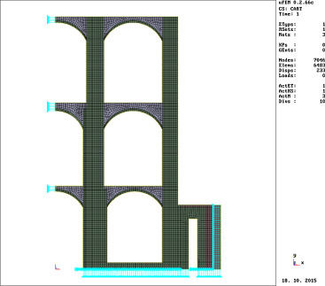
The homogenised material properties can be obtained from laboratory tests of numerical modelling of a relatively small piece of masonry (Brozovsky and Pankaj, 2007 ) but such approach assumes than structures of masonry does not differ too much within the structure. This assumption is correct for testing samples (which usually have regular shape) and for experimental structures but it can be incorrect for real buildings with arches, windows and with non-trivial shapes. An example of such structure is illustrated in Fig. 1 . To simplify the process of numerical model preparation it is proposed to use available information of masonry structure (2D photos or X-ray pictures, for example) as a basis for automatic computation of orthotropic mechanical properties.
|
|
|
Figure 1. Example of masonry structure with complex geometry. |
The proposed work is one of the first steps of an effort to create an automatic tool for computation of homogenised orthotropic properties which have to be based on a structure of the masonry. The current effort concentrates on 2D models but it is possible to extend it to the 3D later.
The approach consists of two main steps. The first one is an obtaining of 2D computer image of masonry structure. It may be a digital picture or X-ray scan. The second step is an analysis of the picture in order to describe the masonry structure in selected points. This step should result in a ready to use 2D finite element method (FEM) model with homogenised orthotropic material properties. The article deals with an approach required for the second step.
Measurement of material anisotropy
Brozovsky and Pankaj (2007) used the tensor scale indices (introduced by Saha and Wehrli, 2004 , for analysis of human bone and then extended for other uses by Saha, 2005 and Genau et al., 2009 ) for an estimation of material properties of material with complicated internal structure. The paper by Brozovsky and Pankaj (2007) compared the results of tensor scale analysis with finite element simulations of numerical with both original and homogenised material properties. It was shown that the tensor scale can be used for such tasks but some form of correlation between tensor scale indices and the mechanical properties has to be established for individual types of structures. The tensor scale can be directly used to find the orientations of material axes for homogenised orthotropic material, though.
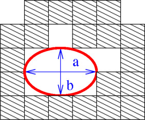
The tensor scale in a material point is defined by sizes of axes of the largest possible ellipse that has centre in that point and that can be fitted in the material of the same type. An example of such ellipse is illustrated in Fig. 2 . There are three main parameters of the ellipse: two axes sizes and the angle between x coordinate axis and the a axis of the ellipse.
|
|
|
Figure 2. Tensor scale parameters (a , b ) in a material point. |
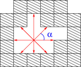
There are several possible approaches to compute the tensor scale. The authors of this paper use the original approach proposed by Saha and Wehrli (2004) . The computation is based on use of certain number of measurements of distances between the studied point and the nearest material point of different material type. The angle a between the all testing lines is usually the same. The procedure is illustrated in Fig. 3 . A more detailed overview of the procedure is available in the paper by Brozovsky and Pankaj (2007) .
|
|
|
Figure 3. Analysis of space with one material type. |
The original approach was designed for measurement of homogeneous materials that include empty spaces. It is use for cases which involve more than one material requires certain modifications.
As it was already stated before it is possible to use the approach to compute orientation of orthotropic material axes. The ellipse orientation angle can be directly used. An estimation of mechanical properties (Young moduli and Poisson ratios) can requires further steps.
Estimation of mechanical properties based on tensor scale
On the basis of numerical studies conducted by authors of this paper it can be stated that only the tensor scale data of the masonry are required for analysis. The analysis of mechanical properties requires masonry model of certain size. Their size will be illustrated below.
The obtained global tensor scale parameters (a , b ) on such area can be used to define a ratio between Young moduli of homogenised orthotropic material as it is shown in Eq. (1) .
|
|
( 1) |
However, in arbitrary case it is not possible to define the values of E1 or E2 just from tensor scale data and the initial E parameters of mortar and bricks. There are of course additional data that have to be included to the computation: volume ratio between mortar and bricks and their mass ratio. It is possible to use neural network approach to define the relations for certain cases but it is out of the scope of this paper. There are also problems with determination of Poisson ratios.
It should be also mentioned that the a /b ratio obtained in Eq. (1) can differ up to 20% from a ratio of Young moduli which can be obtained from finite analysis of the same sample.
There is proposed a simpler approach to obtain values of orthotropic material properties which uses the finite element model of the masonry sample. The finite element model can be subjected to simulated compression and shear tests than can be used to provide Young moduli and Poisson ratios in defined directions. The selection of those directions should utilise the ellipse angle obtained from the tensor scale computation.
The required finite element simulations are illustrated in Fig. 4 . The material properties can be obtained from formulas of linear elasticity which use reactions and x and y deformations from the FEM computations.
|
|
|
Figure 4. Schemes of FEM simulations of simple material tests. |
It is proposed to use such computation to compute a correction factor q for the a /b values that can be computed in other parts of the analysed structure (2) .
|
|
( 2) |
Computer codes
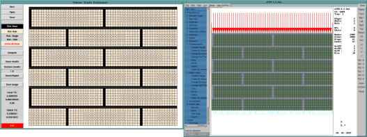
The custom computer codes in the C language have been written for discussed calculations. A general in-house written finite element code uFEM was used to conduct the FEM computations. Fig. 5 shows the user interfaces for the tensor scale evaluating code and for the finite element method code.
|
|
|
Figure 5. Tensor scale code (left) and FEM code (right) evaluating the same model. |
Numerical example
A simple example is provided to illustrate the proposed approach. The basic masonry sample is shown in Fig. 6 where are also shown the larger sizes of the samples. Several levels of larger samples with the same basic structure have been created.
|
|
|
Figure 6. The basic sample (left) and larger samples. |
The analysis of these samples was conducted to show how bit the sample have to be to obtain the results for the a /b ratio.
The a /b ratios for the models are given in Table 1 . The largest model is not shown in Fig. 6 due to its size. The Size parameter in Table 1 describes the number of basic units which were used to create the model. The basic unit is shown in Fig. 6 (a picture at the left). The computed angle of the tensor scale axes (the ellipse orientation) is not shown as it was obviously 0 rad in this case. The expected 0 rad value was also obtained from the computations.
| Model | Size | a /b |
|---|---|---|
| 1 | 2 × 2 | 0.131559 |
| 2 | 4 × 4 | 0.146460 |
| 3 | 12 × 12 | 0.146460 |
It can be concluded that for the given case the model of 4 × 4 basic units is enough for the tensor scale analysis.
A study to determine a necessary number of sample lines (see Fig. 3 ) was also conducted. For simple cases with rectangular bricks it can be shown that 8 sample lines are enough. Larger number of sample lines (12 or more) gives comparable results but it requires greater computational time. In cases with more irregular brick shapes it is required to use at least 12 sample lines.
The initial material properties are given in Table 2 . The selected computed mechanical properties are given in Table 3 . It can be noted that there is slight difference between a /b ratio (0.146) and the computed E1 /E2 ratio (0.145).
| Parameter | Bricks | Mortar | Units |
|---|---|---|---|
| Young modulus | 10 | 1 | GPa |
| Poisson ratio | 0.2 | 0.2 | – |
| Parameter | Size | Units |
|---|---|---|
| Young modulus E1 | 4.67 | GPa |
| Young modulus E2 | 0.68 | GPa |
Summary
The paper discussed a proposed procedure to simplify the computation of homogenised linear elastic orthotropic material properties for finite element modelling of masonry. The proposed procedure is based on tensor scale anisotropy indices which was originally introduced by Saha and Wehrli (2004) . The proposed procedure complements the tensor scale indices by finite element analysis of a masonry sample model which is used to obtain a correction coefficient for the a /b tensor scale data and to obtain the actual sizes of Young moduli of the homogenised material. The obtained data can be used to set the orthotropic properties of other parts of the numerical model: the orientation angle is directly used and the mechanical values are based on the a /b data for the particular part of the model and on the q coefficient which was obtained from the numerical analysis of a masonry sample. The proposed procedure can be used for estimating of initial elastic properties of the material. There are ongoing works that are aimed to allow to use the procedure for estimation of inelastic material parameters.
Conflict of interest
The authors declare that there is no conflict of interest.
Acknowledgment
This outcome has been achieved with the financial support of the Ministry of Education, Youth and Sports of the Czech Republic with use of the institutional support of conceptual development of research in 2015.
References
- Brozovsky and Pankaj, 2007 J. Brozovsky, P. Pankaj; Towards modeling of a trabecular bone; Comput. Struct., 85 (9) (2007), pp. 512–517
- Cajka et al., 2012 R. Cajka, P. Mateckova, M. Stara, M. Janulikova; Testing of pre-stressed masonry corner for tri-axial stress–strain analysis, Life-Cycle and Sustainability of Civil Infrastructure Systems; Proceedings of the 3rd International Symposium on Life-Cycle Civil Engineering, IALCCE 2012 (2012), pp. 1955–1958
- Cajka et al., 2014 R. Cajka, M. Kozielova, K. Burkovic, L. Mynarzova; Strengthening of masonry structures on the undermined area by prestressing; Acta Montan. Slovaca, 19 (2) (2014), pp. 95–104
- Genau et al., 2009 A. Genau, P. Voorhees, K. Thornton; The morphology of topologically complex interfaces; Scripta Mater., 60 (2009), pp. 301–304
- Matysek and Witkowski, 2015 P. Matysek, M. Witkowski; A comparative study on the compressive strength of bricks from different historical periods; Int. J. Archit. Herit. (2015) http://dx.doi.org/10.1080/15583058.2013.855838
- Portioli et al., 2012 F. Portioli, L. Cascini, M. D’Aniello, R.A. Landolfo; Rigid block model with cracking units for limit analysis of masonry walls subject to in-plane loads; Proceedings of the Eleventh International Conference on Computational Structures Technology, Civil-Comp Press (2012), p. 117
- Saha and Wehrli, 2004 P.K. Saha, F.W. Wehrli; A robust method for measuring trabecular bone orientation anisotropy at in vivo resolution using tensor scale’; Pattern Recogn., 37 (2004), pp. 1935–1944
- Saha, 2005 P.K. Saha; Tensor scale: a local morphometric parameter with applications to computer vision and image processing; Comput. Vision Image Underst., 99 (2005), pp. 384–413
- Sykora et al., 2013 M. Sykora, T. Cejka, M. Holicky, J. Witzany; Probabilistic model for compressive strength of historic masonry; European Safety and Reliability Conference, ESREL 2013 (2013), pp. 2645–2652
- Witzany et al., 2014 J. Witzany, T. Cejka, R. Zigler; Failure mechanism of compressed short brick masonry columns confined with FRP strips; Constr. Build. Mater., 63 (2014), pp. 180–188
- Witzany and Zigler, 2015 J. Witzany, R. Zigler; Failure mechanism of compressed reinforced and non-reinforced stone columns; Materiaux et Constructions, 48 (5) (2015), pp. 1603–1613
- Zucchini and Lourenco, 2004 A. Zucchini, P.B. Lourenco; A coupled homogenisation-damage model for masonry cracking; Comput. Struct., 82 (2004), pp. 917–929
Document information
Published on 05/10/16
Licence: Other
Share this document
Keywords
claim authorship
Are you one of the authors of this document?


