m (Cinmemj moved page Draft Samper 690379007 to Roca et al 2020b) |
|||
| (2 intermediate revisions by the same user not shown) | |||
| Line 547: | Line 547: | ||
[[Image:Draft_Samper_690379007-image9.png|600px]] </div> | [[Image:Draft_Samper_690379007-image9.png|600px]] </div> | ||
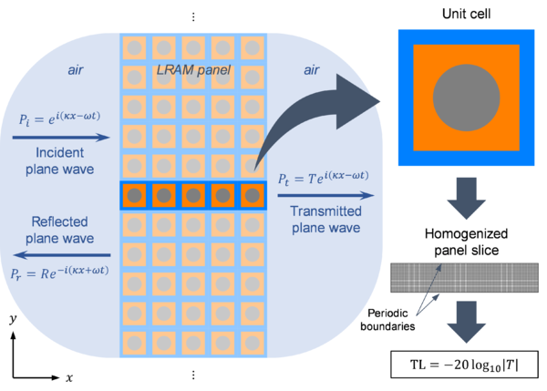
| − | <div class="center" style="font-size: 75%;">'''Fig. 9'''. LRAM-based panel problem setting for computing its transmission loss. The macroscopic domain consists of an infinitely extended panel with a certain thickness. Its microscale is modelled as a periodically repeated unit cell with a given configuration that allows it to produce local resonance effects. In order to compute the transmission loss, acoustic plane waves propagating in the direction normal to the panels’ surfaces are considered. On the front side, there are two waves travelling in opposite directions corresponding to the incident and reflected waves, while on the rear side, there is only the transmitted wave propagating away from the panel. The ratios between these waves’ amplitudes define the reflection and transmission coefficients, <math display="inline">R</math> and <math display="inline">T</math>, respectively. | + | <div class="center" style="font-size: 75%;">'''Fig. 9'''. LRAM-based panel problem setting for computing its transmission loss. The macroscopic domain consists of an infinitely extended panel with a certain thickness. Its microscale is modelled as a periodically repeated unit cell with a given configuration that allows it to produce local resonance effects. In order to compute the transmission loss, acoustic plane waves propagating in the direction normal to the panels’ surfaces are considered. On the front side, there are two waves travelling in opposite directions corresponding to the incident and reflected waves, while on the rear side, there is only the transmitted wave propagating away from the panel. The ratios between these waves’ amplitudes define the reflection and transmission coefficients, <math display="inline">R</math> and <math display="inline">T</math>, respectively.</div> |
| Line 562: | Line 562: | ||
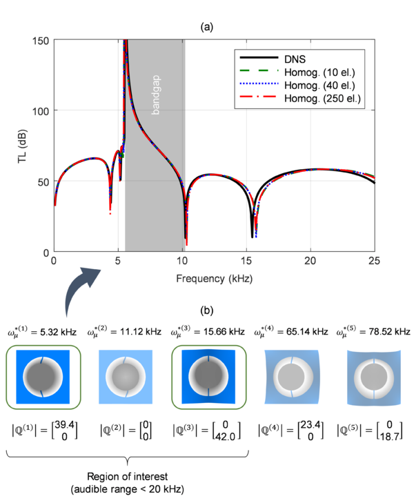
<div class="center" style="font-size: 75%;">'''Fig. 10'''. Validation of the proposed homogenization scheme. (a) The transmission loss of a panel has been computed through a direct numerical simulation and the results are compared with those obtained by the proposed homogenization framework. (b) Internal resonance modes for the unit cell design considered. Notice that only the first 3 modes lie in the audible frequency range, of which only 2 have non-negligible components in the coupling vector and only the first is responsible for causing local resonance effects for waves propagating in the longitudinal direction. Results adapted from <span id='cite-_Ref37801010'></span>[[#_Ref37801010|Article I]].</div> | <div class="center" style="font-size: 75%;">'''Fig. 10'''. Validation of the proposed homogenization scheme. (a) The transmission loss of a panel has been computed through a direct numerical simulation and the results are compared with those obtained by the proposed homogenization framework. (b) Internal resonance modes for the unit cell design considered. Notice that only the first 3 modes lie in the audible frequency range, of which only 2 have non-negligible components in the coupling vector and only the first is responsible for causing local resonance effects for waves propagating in the longitudinal direction. Results adapted from <span id='cite-_Ref37801010'></span>[[#_Ref37801010|Article I]].</div> | ||
| − | |||
===3.2 Computational design of acoustic metamaterials=== | ===3.2 Computational design of acoustic metamaterials=== | ||
| Line 766: | Line 765: | ||
<div class="center" style="width: auto; margin-left: auto; margin-right: auto;"> | <div class="center" style="width: auto; margin-left: auto; margin-right: auto;"> | ||
| − | [[ | + | [[File:Draft_Samper_690379007_3146_Fig 16.png]]</div> |
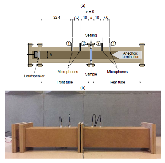
<div class="center" style="font-size: 75%;">'''Fig. 16'''. Experiment setup for normal-incidence transmission loss measurements. (a) Schematic representation showcasing the four microphone positions and holding of the sample panel. (b) Actual impedance tube employed in the experiments. Figure from <span id='cite-_Ref37801261'></span>[[#_Ref37801261|Article III]].</div> | <div class="center" style="font-size: 75%;">'''Fig. 16'''. Experiment setup for normal-incidence transmission loss measurements. (a) Schematic representation showcasing the four microphone positions and holding of the sample panel. (b) Actual impedance tube employed in the experiments. Figure from <span id='cite-_Ref37801261'></span>[[#_Ref37801261|Article III]].</div> | ||
| − | |||
====3.3.2 Impedance tube measurements==== | ====3.3.2 Impedance tube measurements==== | ||
Latest revision as of 15:07, 28 October 2020
ABSTRACT
The notion of metamaterials as artificially engineered structures designed to obtain specific material properties, typically unachievable in naturally occurring materials, has captured the attention of the scientific and industrial communities. Among the broad range of applications for such kind of materials, in the field of acoustics, the possibility of creating materials capable of efficiently attenuating noise in target frequency ranges is of utmost importance for a lot of industrial areas. In this context, the so-called locally resonant acoustic metamaterials (LRAMs) can play an important role, as their internal topology can be designed to exhibit huge levels of attenuation in specific frequency regions by taking advantage of internal resonance modes. With a proper, optimized topological design, LRAMs can be used, for instance, to build lightweight and thin noise insulation panels that operate in a low-frequency regime, where standard solutions for effectively attenuating the noise sources require dense and thick materials.
Given the importance of the topological structure in obtaining the desired properties in acoustic metamaterials, the use of novel numerical techniques can be exploited to create a set of computational tools aimed at the analysis and design of optimized solutions. These are based on three fundamental pillars: (1) the multiscale homogenization of complex material structures in the microscale to get a set of effective properties capable of describing the material behavior in the macroscale, (2) the model-order reduction techniques, which are used to decrease the computational cost of heavy computations while still maintaining a sufficient degree of accuracy, and (3) the topology optimization methods that can be employed to obtain optimal configurations with a given set of constraints and a target material behavior. This set of computational tools can be applied to design acoustic metamaterials that are both efficient and practical, i.e. they behave according to their design specifications and can be produced easily, for instance, making use of novel additive manufacturing techniques.
RESUM
La concepció dels metamaterials com a estructures dissenyades artificialment amb l’objectiu d’obtenir un conjunt de propietats que no són assolibles en materials de manera natural, ha captat l’atenció de les comunitats científiques i industrials. Dins de l’ampli ventall d’aplicacions que se’ls pot donar als metamaterials, si ens centrem en el camp de l’acústica, la possibilitat de crear un material capaç d’atenuar de manera efectiva sorolls en rangs de freqüència concrets és de gran interès en multitud d’indústries. En aquest context, els anomenats locally resonant acoustic metamaterials (LRAMs) destaquen per la possibilitat de dissenyar la seva topologia interna per tal que produeixin elevats nivells d’atenuació en regions concretes de l’espectre de freqüències. Amb un disseny topològic òptim, els LRAMs poden servir, per exemple, per a la construcció de panells lleugers aïllants de soroll, que operin en rangs de freqüències baixos, en els quals la solució clàssica requereix de materials d’elevada densitat i espessor.
Donada la importància de l’estructura topològica dels metamaterials acústics en l’obtenció de les propietats desitjades, resulta convenient l’ús de mètodes numèrics punters per al desenvolupament d’un conjunt d’eines computacionals que tinguin per objectiu l’anàlisi i el disseny de solucions òptimes. Tals eines es fonamenten en tres pilars: (1) la homogeneïtzació multiescala d’estructures de material complexes a una escala micro que derivi en l’obtenció de propietats efectives que permetin descriure el comportament del material a una escala macro, (2) tècniques de reducció per minimitzar l’esforç computacional mantenint nivells de precisió suficients i (3) mètodes d’optimització topològica emprats per a l’obtenció de configuracions òptimes donat un conjunt de restriccions i unes propietats de material objectiu. Aquestes eines computacionals es poden aplicar al disseny de metamaterials acústics que resultin eficients i pràctics a la vegada, és a dir, que es comportin segons les especificacions de disseny i siguin fàcilment fabricables, per exemple, mitjançant tècniques punteres d’impressió 3D.
PREFACI
La meva ment curiosa sempre m’ha portat a voler adquirir més coneixements i és el motiu que em va empènyer a formar-me en l’àmbit de la ciència i tecnologia. Aquesta tesi representa la culminació d’aquest llarg procés, un viatge en el que més enllà de formar-me i adquirir aquests coneixements tan anhelats, he crescut com a persona, m’he conegut a mi mateix i he trobat el camí a seguir. No és estrany sentir dir que fer una tesis doctoral pot resultar una “tortura”. La realitat, per mi, ha estat totalment diferent. Si bé és cert que ha suposat un repte, és un repte que he gaudit en tot moment. Inclús les parts més dificultoses m’han aportat beneficis, tant a nivell personal com possibilitant la obertura de nous camins per explorar. I, en general, em sento satisfet amb el resultat final. Tot això no hauria estat possible sense un conjunt de persones que m’agradaria mencionar a continuació, per mostrar-los el meu profund agraïment per haver-me ajudat o acompanyat en aquest viatge i haver-lo fet possible.
En primer lloc, vull agrair-li a Xavier Oliver el fet d’haver-me brindat l’oportunitat de realitzar aquesta tesi. Ell és qui ha estat al capdavant promovent la línia d’investigació en la que s’ha desenvolupat la tesi i, en aquest sentit, és qui l’ha fet possible. Per altra banda, vull agrair també la seva figura com a mentor, per haver-me ajudat i ensenyat què significa ser investigador.
M’agradaria agrair també la tasca dels directors d’aquesta tesi, el Juan Carlos Cante i l’Oriol Lloberas, pel seu ajut i recolzament en els moments que ho he necessitat. En especial, voldria agrair al Juan Carlos haver estat present i recolzant-me en moments de dificultat personals, per haver-me donat valuosos consells per seguir endavant i no defallir en la seva tasca de formar-me com a docent.
Tot seguit vull agrair a les persones que, d’una manera o altra, han fet possible que hagi pogut realitzar aquest treball. D’entrada a Àlex Ferrer, per haver-me convençut a iniciar aquesta aventura. Al CIMNE, per haver proporcionat l’entorn i els recursos necessaris. També vull mostrar el meu agraïment al professor Mahmoud Hussein, per haver possibilitat la meva estància a la Universitat de Colorado a Boulder i brindar-me l’oportunitat d’explorar noves maneres de seguir explorant la línia d’investigació de la tesis. A la Teresa Pàmies, per haver-me ajudat en les sessions al laboratori d’acústica. Voldria agrair també a HP i, en particular, a Lucas Rotllant, per haver proporcionat el seu ajut en l’adquisició dels prototips emprats en la part experimental de la tesis. Per últim a Oriol Guasch, qui va inspirar la línia d’investigació centrada en els metamaterials acústics.
Per altra banda, voldria fer especial menció a tots els companys i companyes que m’han acompanyat, en un moment o altre, i han compartit amb mi el camí durant aquests anys de doctorat: en Joaquín, l’Àlex, l’Alfredo, en Manuel, en Marcelo, la Lucía, l’Alejandro i el Sergi. En particular també a la Laura i en Daniel, per compartir penúries i alegries durant els mítics dinars al búnquer (i quan el temps acompanyava a la terrassa). I aquest últim també pel seu suport, a nivell de la tesis i a nivell personal.
Per acabar, m’agradaria expressar el meu profund agraïment a tots les meus amics i familiars. En particular als meus pares, la Remei i l’Isidre, per ser els responsables que hagi arribat tan lluny. I al meu pare també per haver fet la seva aportació en la tesis, possibilitant la realització dels experiments. Per últim, vull agrair a la Laura tots els anys que ha passat al meu costat, per haver-me mostrat lo bonica que pot ser la vida i haver cregut sempre en mi i el meu potencial com a persona.
Chapter 1
MOTIVATION AND SCOPE
I like to define progress as the ability of making possible what once was impossible. Challenging the limits of nature is a quality of our species that has brought us to an era where we can travel thousands of kilometers in a matter of hours, communicate almost instantly with other people anywhere in the planet or even explore the universe beyond our solar system. The progress of humanity is a proof that we are good at solving problems, but in order to do that, what is most important is for the right questions to be raised first. This is precisely our task, as scientists, and ultimately the driving force that makes us succeed and evolve as a civilization.
This constant questioning is carried out in every existing field of science. However, this work will be focused on what can be considered a very clear example of what it means to surpass the limits of what is possible: metamaterials. The notion behind this concept lies on its own etymological meaning, combining the word material with the prefix meta, which denotes “beyond”, to refer to “materials with properties beyond those found naturally”. The prospect applications of such kind of materials have attracted the attention of the scientific and industrial communities for the past decades. Technically speaking, metamaterials consist of artificially engineered materials with the ability to manipulate waves for different outcomes. The nature of these waves is what determines the kind of application, offering a wide range of possibilities.
To narrow down the research, this study will focus on acoustic problems. The so-called acoustic metamaterials are capable of producing frequency bandgaps, i.e. selected regions in the frequency spectrum where waves’ propagation is effectively stopped, due to local resonance phenomena. For practical purposes, this translates in the ability to attenuate sound pressure waves at targeted frequency ranges, typically in the lower end of the spectrum, where a classical approach would require huge amounts of mass. This is a very interesting property, for instance, for cheap and lightweight sound insulation in many industrial sectors including construction or transport.
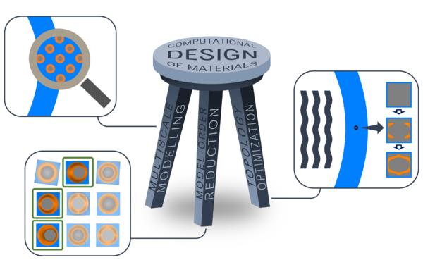
With the current and potential growth of manufacturing technologies, including novel techniques such as 3D-printing, practical realizations of metamaterials are getting closer. Furthermore, given the importance of the role their design plays in obtaining the desired properties, there is a need for fast and efficient resources capable of performing this task. In this context, the aim of this work is to develop a set of computational tools for the analysis and design of acoustic metamaterials. These tools are grounded on three fundamental pillars in the field of computational design of materials: (a) multiscale modelling, (b) model-order reduction techniques, and (c) topology optimization.
Additionally, as part of this work, the application of the aforementioned tools for the study, design and characterization of different kinds of acoustic metamaterials is performed. The obtained results and the concept of local resonance as the mechanism responsible for the attenuating capabilities of acoustic metamaterials is assessed through a set of experiments in an impedance tube with 3D-printed prototypes.
Chapter 2
STATE OF THE ART
2.1 Metamaterials technology
In the previous chapter, the concept of metamaterials has been introduced to describe artificially engineered structures capable of manipulating waves and exhibiting non-conventional behavior as a result. A more general definition is provided by Cui et al. (2010) where a metamaterial is considered “a macroscopic composite of periodic or non-periodic structure, whose function is due to both the cellular architecture and the chemical composition” [1]. According to this description, metamaterials gain their properties by combining materials with different chemical compositions and/or by rearranging their internal topology.
2.1.1 Early days of metamaterials
Even though the term metamaterial has been used since the late 1990’s, the notion of “artificial” materials had already been explored in the past. For instance, in 1948, Kock managed to manipulate the refractive index of an artificial media created by periodically arranging conducting spheres, disks and strips [2]. However, it was not until 1967, when Veselago conducted the first theoretical study on plane-wave propagation in materials with simultaneously negative permittivity and permeability [3]. With his work, Veselago established the physics behind the metamaterial’s ability to manipulate waves, in the context of electromagnetism. Those theoretical findings would not be validated until some decades later, with the first experimental realizations of the so-called double-negative metamaterials. Smith et al. (2000) introduced a composite structure based on split rings resonators (SRRs) that exhibited a frequency band over which both the effective permittivity and permeability were negative [4]. The SRRs is a common metamaterial design that consists of a set of concentric conducting rings with a gap on each. It is used to achieve magnetic resonance in a selected frequency band, which is responsible for the negative refractive index of the metamaterial [5].
2.1.2 Phononic crystals and acoustic metamaterials
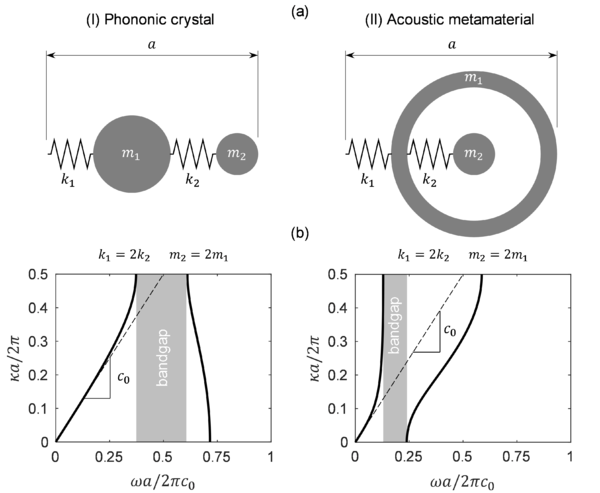
While the idea of waves’ manipulation to obtain unusual properties was born in the context of electromagnetism, it rapidly extended to other fields where the material response is also governed by waves’ propagation mechanisms. In particular, by applying the concept to sound waves manipulation, the notion of acoustic metamaterials was introduced. Analogously to how electromagnetic metamaterials exhibit exotic behavior by showing negative effective permittivity and permeability, in the context of acoustic metamaterials, this translates in negative effective mass density and bulk modulus. In this case, these are the source of certain regions in the frequency spectrum, called frequency bandgaps, where sound waves effectively stop propagating. There are two known mechanisms by which this can be achieved: Bragg scattering and local resonance effects [6].
Bragg scattering occurs in periodic media, typically consisting of a lattice with repeating unit cells, which are known as phononic crystals (PCs). The physics behind Bragg scattering effects is discussed in [7]. An important aspect to notice is that in order for Bragg scattering to manifest, the crystal's dimensions (i.e. the periodicity size) must be larger than the incident wave’s wavelength. This means that bandgaps produced by PCs usually appear at frequency ranges higher than those interesting for acoustic applications based on sound insulation. However, PCs are still a topic of active research due to their applications in several areas including: superlensing, for which PCs can be used for medical and non-destructive sensing [8], energy harvesting through the interaction between PCs bandgaps and piezoelectric microstructures [9], thermal control using PCs with nano-scale dimensions [10] and opto-mechanics, where PCs are used in combination with their electromagnetic analogous, photonic crystals, for communication and sensing applications [11], among others. Also in this context, the notion of acoustic black holes (ABHs) [12], which typically operate in the same frequency range as PCs, has recently been proposed for isolating vibrations in plates [13].
The other phenomenon capable of producing frequency bandgaps is local resonance. Metamaterials that employ this mechanism to get their unusual properties are known as locally resonant acoustic metamaterials (LRAMs). As with PCs, the structure of LRAMs contains a lower scale with a certain topology that triggers the effects causing the appearance of frequency bandgaps. While periodicity is not a requirement in this case, it is still preferable for most cases, as it enables a unit cell-based description of its dynamical properties as well as ease in the process of introducing resonating elements (for manufacturing purposes, for instance). A main difference of LRAMs in contrast to PCs is that the characteristic size of the lower scale needs to be smaller than the incident wave’s wavelength [14]. This requirement is important for two reasons: (1) it allows using LRAMs for low-frequency applications (which are interesting especially in sound insulation problems) and, (2) in cases where periodicity is present, it gives the metamaterial the ability to be regarded as an effective medium.
As the name suggests, local resonance takes advantage of resonating effects in the internal structure of the metamaterial to effectively stop the propagation of waves at a macroscopic scale. In order for it to occur, the lower scale must be composed of certain resonating elements. These resonating elements typically contain a compliant component, the purpose of which is to play the role of a spring, and a dense component acting as mass, the combination of which resonates at the desired frequencies in order to produce bandgaps. It is important for local resonance effects to manifest that each unit cell vibrates independently of the others. For this reason, these effective spring-mass systems are typically embedded in a stiff matrix or frame.
While LRAMs are especially interesting for sound insulation, shielding and noise blocking purposes [15, 16], there are other kind of application for which they can also be considered. These include subwavelength focusing, where LRAMs allow to break the diffraction limit and can be used as an alternative to conventional imaging technologies [17–19], or cloaking applications, where an object becomes “invisible” to acoustic waves by guiding them around it instead of being scattered [20–23].
2.2 Computational design of materials
Computational modelling is a field that has experienced a significant growth in the last decades and has been infiltrating in a broad range of application areas. In several contexts, experimental validation of a phenomenon or the evaluation of a certain behavior is difficult to reproduce, either because of its complexity or simply due to the lack of resources. In such situations, computational modelling offers the ability to perform a preliminary (and sometimes sufficient) characterization allowing great savings of time and resources. Additionally, it can be used for design purposes, allowing the obtention of desired features and optimal results. In this regard, the field of computational design of materials, which is growing alongside new developments in computer technologies, is progressively getting more attention in several disciplines. The foundation upon which it is based can be synthesized with three main branches: the multiscale modelling, model-order reduction techniques and topology optimization.
2.2.1 Multiscale modelling
Homogenization-based or multiscale techniques offer the possibility of accounting for microstructural physical phenomena and their impact in a macroscopic level at a relatively inexpensive computational cost compared to direct numerical simulations or concurrent multiscale techniques. In the context of solid mechanics, the first theoretical developments based on the obtention of macroscopic properties from heterogeneous materials were carried out by Hill (1965) [24] and Mandel (1971) [25], among others. Since then, these theories have derived to more sophisticated models, mostly based on finite element methods, allowing their use in a computational context and giving them several practical applications.
For instance, homogenization models in which the constitutive information driving the macroscopic analysis is computed from consecutive interaction between the macro and microscales can be found in Feyel and Chaboche (2000) [26] or Kouznetsova et al. (2001) [27]. This approach has been successfully applied to a wide range of quasi-static contexts, including complex material behavior such as softening and localization phenomena [28–30], multi-physics [31] or large deformations [32], among others. However, developments in the context of dynamic problems, where inertial effects are relevant, started to emerge only in more recent years with the works of Karamnejad et al. (2013) [33], Pham et al. (2013) [34] or De Souza Neto et al. (2015) [35, 36], who count among the first to propose a formulation in rigorous variational form based on a generalized Hill-Mandel principle along with kinematic admissibility between scales.
2.2.2 Model-order reduction techniques
Model-order reduction techniques are an effective tool to reduce the computational cost associated to large-scale problems. They are based on retaining the relevant information of the problem by using physical insight and intuition or through statistical correlation between input data and output results. In either case, the so-called projection-based methods have gained prominence in recent years. In projection-based methods a set of solutions is computed in an offline stage and a subspace of a reduced basis is built with the most dominant ones. Then, in the online stage, the governing equations are projected onto this reduced-order subspace, allowing faster computational evaluation while preserving the required accuracy for the problem.
The most popular model-order reduction technique is the proper orthogonal decomposition (POD). In Chatterjee’s work, a review on the fundamental idea behind the POD can be found [37]. Furthermore, Krysl et al. (2001) provided a rigorous discussion on this method [38]. Other projection-based methods used, more specifically, in the context of wave propagation in periodic media were firstly proposed by McDevitt et al. (2001) [39]. Research in this line was followed by Hussein and Hulbert (2006), who presented a method for fast dispersion curves calculation based on a mode-enriched model, in a multiscale context, by selecting a set of Bloch eigenvectors to build a projection subspace [40].
2.2.3 Topology optimization
Topology optimization techniques have been spreading progressively to a wide range of fields for the past decades. Typically, they are based on computing the gradient of a functional in order to steer the algorithm into gradually improving a certain objective function. The first notions were introduced in the work of Bendsøe et al. (1988), which proposed a method that relied on homogenization theory to define a set of macroscopic properties and perform the topology optimization through the parametrization of the microstructure [41]. The solid isotropic material with penalization (SIMP) method was proposed in 1989 also by Bendsøe [42] and has been improved by several works later [43], [44]. Since then, it has become one of the most used techniques and applications can be found in several disciplines, including compliant mechanisms [45], geometrical non-linear structures [46], multi-physics actuators [47], photonic crystal structures [48] or phononic bandgap materials [49], among others.
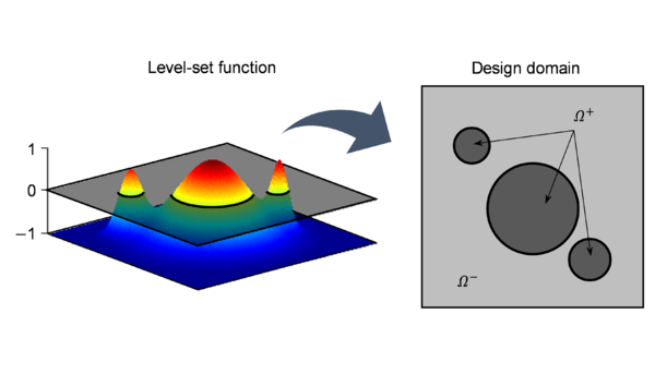
Theories based on topological derivative were first suggested by Eschenauer et al. (1994) [50] and Sokolowki and Zochowki (1999) [51]. They resort to computing a function evaluating the sensitivity of the specific problem to the appearance of an infinitesimal void in the material domain. In contrast, shape derivative methods are based on computing the sensitivity of the problem when a unit normal deformation is applied on the boundaries of the domain. In this context, level-set methods used in image processing were adapted to work together with the shape derivative [52, 53] and later also with the topological derivative [54, 55] as a tool to update the topology at each optimization step. Alternatively, recent methods combining a 0-level set function and an estimated topological derivative are being developed by Oliver, et al. (2019) [56] and Yago, et al. (2020) [57] to overcome the high computational cost of the aforementioned techniques.
2.2.4 Computational modelling of acoustic metamaterials
Research on acoustic metamaterials has derived in several approaches that go from simple analytical studies to sophisticated computational models capable of accounting for their intrinsic exotic behavior. For instance, in the work of Xiao et al. (2011), an analytical model of a 1D string with spring-mass resonators is developed to study the bandgap formation mechanisms showed by acoustic metamaterials [58]. In the context of numerical modelling, most of the early works focused on periodically repeated microstructures where Bloch-Floquet boundary conditions can be applied to study the dispersion properties of 2D and 3D unit cells [59, 60]. In this line, Hussein (2009) proposed a Bloch-based model to characterize the local resonance effects in periodic structures [61].
Other approaches have focused on retrieving effective properties from acoustic metamaterials by means of homogenization theory. In this regard, Fokin et al. (2007) developed a method to obtain properties from experimental measurements of the reflection and transmission coefficients of LRAMs [62]. Nemat-Nasser et al. (2011) presented a homogenization method based on Floquet theory applied to periodically arranged elastic composites [63]. In more recent developments, the use of computational homogenization frameworks based on variational formulations have been successfully applied to acoustic problems and, in particular, for the study and characterization of local resonance effects in LRAMs. For instance, Sridhar et al. (2016) proposed a Craig-Bampton mode synthesis substructuring method to reduce the set of degrees of freedom in the microscale accounting only for the relevant resonance modes, leading towards an emergent enriched continuum [64, 65]. A similar approach is proposed in the present work [66, 67], but by performing a unit cell’s system split into a quasi-static and inertial components based on a set of simple hypotheses that do not require to resort to substructuring techniques to identify the relevant resonance modes.
Given the intrinsic narrowband nature of frequency bandgaps caused by local resonance effects, research can be found in the literature aiming at enlarging the attenuating properties of acoustic metamaterials. In this regard, Krushynska et al. (2014) presented the first attempts towards the design of acoustic metamaterials by studying the effects of certain parameters in their topology [68]. Additionally, Matsuki et al. (2014) proposed a topology optimization-based method to find optimal LRAM configurations with multiple attenuation peaks [69].
Another approach that has been studied consists of exploiting the viscoelastic behavior of certain materials used in typical acoustic metamaterial configurations. In this context, Hussein and Frazier (2013) [70] introduced the concept of metadamping referring to the damping emergence phenomenon produced when viscous dissipation is used in combination with local resonance effects [71, 72]. The effects of dissipative behavior in acoustic metamaterials has also been studied analytically by Manimala and Sun (2014) [73]. Furthermore, numerical generalized viscoelastic models have been developed by Krushynska et al. (2016) [74] and Lewinska et al. (2017) [75] to characterize the attenuation performance of LRAMs.
Other attempts in this endeavor include, for instance, the addition of holes on a plate with resonating pillars. The idea was proposed by Bilal and Hussein (2013), who called this phenomenon the trampoline effect, given the analogy between springboards and recreational trampolines with the holed plate, the increased compliance of which enhances the motion of the pillars at the resonance frequencies [76].
2.3 Acoustic metamaterial designs
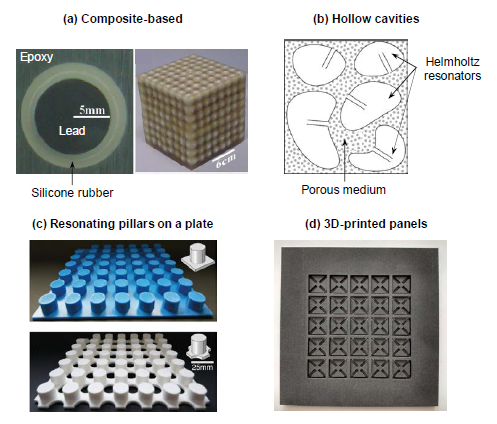
The first actual realizations of an acoustic metamaterial came from the work of Liu (2000), who built a composite structure that possessed negative elastic constants and exhibited frequency bandgaps around 400 and 1100 Hz [14]. The material consisted of a 2.1 cm slab with a structure made of an epoxy matrix with randomly dispersed rubber-coated lead spheres. In this case, the elastic properties of the silicone rubber coating made it act as a spring, which combined with the high density of the lead spheres gave rise to local resonances at lower frequency ranges. The concept of building acoustic metamaterials based on the combination of different material properties was implemented in several other experimental demonstrations [77–81], where typically a polymer-based structure was used to host rubber-coated metal inclusions.
There are several other experimental realizations of acoustic metamaterials exploiting the local resonance phenomenon which are based on different configurations. For instance, the idea of introducing hollow topologies or cavities in the material, acting as Helmholtz resonators capable of producing bandgaps, has been explored [82, 83]. Designs with different kinds of resonators can also be found, including beam resonators [84], pillared plates [85–90] or membranes [91–93], among others. Recent works have also studied the effects of irregularities and random structures in acoustic metamaterials without periodic arrangements [94–97].
While the idea and properties of acoustic metamaterials have been demonstrated, both theoretically and experimentally, their intrinsic complex nature still make them far from practical realizations. In this regard, new kinds of acoustic metamaterials meant to be built monolithically through an additive manufacturing process have been devised. Since only one material is considered, one cannot resort to the combination of material properties in order to achieve the resonances in the desired frequency range. This highlights the importance of the topology and geometrical features in the design for these kinds of acoustic metamaterials. Experimental implementations of such metamaterials can be found in the work of Claeys et al. (2016), in which they demonstrate the attenuating capabilities of acoustic enclosures composed of unit cells with internal resonators that were fully 3D-printed [98]. More recently, Leblanc and Lavie (2017) came up with another 3D-printed configuration based on a resonating membrane [100], while McGee et al. (2019) devised a 3D-printed foam with hollow spheres capable of producing low-frequency bandgaps [101]. Finally, as a result of the present work, a 3D-printed prototype LRAM panel has been designed and tested numerically and experimentally to assess its transmission loss capabilities [99].
Chapter 3
SCIENTIFIC CONTRIBUTIONS
3.1 Multiscale homogenization framework
3.1.1 Multiscale virtual power principle
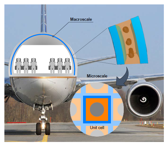
Aiming at characterizing the behavior of LRAMs and to provide a computational framework that can be employed in the design of such metamaterials, a homogenization model has been developed. The multiscale framework is based on the ability to identify a repeating structure (unit cell) in what is considered a macroscopic domain. In the present context, this unit cell configures the metamaterial structure and is treated as the microscale (see Fig. 5).
In this regard, a kinematic relation is established between the macro and microscales in terms of the displacement field and its symmetric gradient (i.e. strain field). Namely,
|
|
(1) | |
|
|
(2) |
where and correspond to the displacement fields in the macro and the microscales, respectively, and is the micro-fluctuation field. Note in Eqs. (1) and (2) the use of to refer to the spatial coordinates in the macroscopic domain and to refer to their microscale counterparts ( are the coordinates of the unit cell’s geometric center). The symbols and denote the gradient operators in the macro and microscale contexts and the superscript is used to specify the symmetric component of . A specific set of restrictions over the micro-fluctuation field and its symmetric gradient, and , need to be considered in order to set the kinematic relation between scales.
Then, an energetic equivalence between both scales is established by means of an extended version of the classical Hill-Mandel principle, in which inertial effects can be accounted for (also known as multiscale virtual power principle [36]). In its variational form, the postulate reads
|
|
(3) |
for all kinematically admissible (i.e. constrained by Eqs. (1) and (2)) displacement-rate fields and . In Eq. (3), and are the macro and microscale stress tensors, respectively, while and denote the D’Alembert forces density vectors (which include the inertial effects), also for the macro and microscales. The notation is employed here to refer to the average value of over the unit cell domain .
3.1.2 Lagrange functional-based reformulation
The problem can be reformulated as a saddle point problem where the specific kinematic restrictions are introduced via Lagrange multipliers. In this context, by associating these Lagrange multipliers to the minimal kinematic restrictions, the problem results in the following system of equations:
| (4)
(5) (6) |
where and are the Lagrange multipliers and the perturbation fields , and , are totally unconstrained. Note that in Eq. (6), the macroscopic strain field is denoted by . The key aspect about associating the Lagrange multipliers to the minimal kinematic restrictions (derived from Eqs. (5) and (6)), is that one can give them a physical interpretation. This can be seen by appropriately manipulating Eq. (4) to obtain:
|
|
(7) | |
|
|
(8) |
where the operator is used to denote the symmetric outer product between tensors (i.e. ). Specific details on the derivation of these results are given in Article I. Note that according to Eqs. (7) and (8), the Lagrange multiplier can be interpreted as the opposite macroscopic D’Alembert force density vector, , while the other Lagrange multiplier, , is directly interpreted as the macroscopic stress tensor, .
Considering a Galerkin-based finite element discretization of Eqs. (4)-(6), the resulting system can be expressed in matrix form as
|
|
(9) |
where , are the standard stiffness and mass matrices, and are matrices applying the minimal kinematic restrictions, is the vector of nodal micro-displacements and is another vector containing body forces data. Again, the reader is referred to Article I for a complete derivation of all these terms.
The system in Eq. (9) clearly shows that the microscale gets the information from the displacement and strain fields, and , in the associated macroscopic point (which become actions in the microscale system). These, along with the body forces data given by (if present), are used to obtain the effective response, the information of which is condensed on the Lagrange multipliers, and , and returned to the macroscale as the D’Alembert force density and stress (acting as reactions in the microscale context).
3.1.3 Application to acoustic metamaterials problems
Up to this point, the proposed formulation is general for as long as homogenization theory holds, which means: (a) it exists a separation of scales enough to satisfy (i.e. inertial effects or force excitations in the macroscale have a wavelength higher than one order of magnitude compared to the characteristic size of the microscale ) and (b) the kinematic relation between both scales reflects the actual material interaction in the microscale. The better these two conditions are satisfied, the better the microscale effects on the macroscale will be captured by the homogenization scheme.
However, in the context of this work, where the goal of the proposed multiscale framework is to characterize the behavior of acoustic metamaterials, additional hypotheses can be considered to further simplify the model. In particular:
- (1) Supported by the separation of scales condition, , the macroscopic strain acceleration field can be neglected, , because no deformation modes will be excited. Although this condition limits the applicability of the homogenization framework to cases in the low-frequency regime, it is also a requirement for local resonance phenomena to arise. Thus, the model is still capable of characterizing the behavior of LRAMs.
- (2) The density distribution on the unit cell satisfies , i.e. its center of mass lies close to the geometric center . This occurs, for instance, if the unit cell topology is symmetric with respect to its geometric center .
- (3) Body forces are neglected, so that the D’Alembert force density vector contains only its inertial component, i.e. and (with being the density distribution on the microscale and denoting the time derivative of the linear momentum in the macroscale).
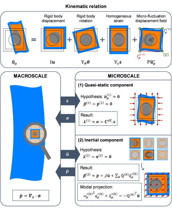
Furthermore, given the periodic nature of acoustic metamaterial structures, and since the study on the microscale is focused on a unit cell, the appropriate set of kinematic restrictions considered for the micro-fluctuation field consists of: (1) applying periodic boundary conditions and (2) prescribing the value of at some point on the unit cell’s boundary (in order to avoid rigid body motion). These are used instead of the minimal kinematic conditions as they give more accurate results in the present context. In Fig. 6 a schematic representation of the micro-displacement field is shown. The derivation of the matrices , , and (from Fig. 6) is given in Article I.
In order to proceed with the unit cell system resolution, in the context of acoustic metamaterials, the system in Eq. (9) will be split into two subsystems. Under the assumptions considered, this split will allow us to isolate the quasi-static response from the inertial one, simply by dealing with the actions of the system (i.e. the macroscopic displacement and strain fields, and ) separately.
The quasi-static subsystem is derived when is considered, so it represents the system’s response to a homogeneous strain action, . According to hypothesis (a), by assuming , the inertial response of this subsystem can be neglected (hence the name quasi-static). In this regard, one can anticipate the resulting displacement field to satisfy and, according to Eq. (7) and considering , then . This subsystem can be solved by means of classical homogenization theory and one is able to obtain a value for the effective macroscopic stress as a result,
|
|
(10) |
where is the resulting effective homogenized constitutive tensor.
On the other hand, the inertial subsystem takes into account the effect of a homogeneous displacement in the action vector, so in this case . Since body forces are being neglected here (according to hypothesis (c)), it should be noted that the sum of both subsystems accounts for the complete action vector, hence giving the full response of the original microscale system. In this case, given the nature of the action for this system (that essentially simulates a homogeneous, rigid body-like displacement of the unit cell) one can anticipate the traction forces appearing as a reaction to be negligible, ( here referring to the outward unit normal vector at the unit cell’s boundaries). Furthermore, in virtue of hypothesis (b), it is reasonable to assume that the global contribution of the resulting moments will also be small, thus the term can be neglected too. In this regard, according to Eq. (8), one can expect , and obtain an effective macroscopic inertial force density as a result,
|
|
(11) |
where is the average density of the unit cell, is the nodal vector containing the free degrees of freedom of the micro-fluctuation acceleration field, , and is a pseudo-density coupling matrix.
At this point, it is important to remark two key aspects:
- (1) By expressing the microscale system in the form of Eq. (9), one gets enough physical insight of the problem to properly apply the simplifying hypotheses considered, granting us with the ability to uncouple the macroscopic stress from the macroscopic inertial force density and associate the former with the macroscopic strains only (through Eq. (10)), and the latter with the macroscopic acceleration field (through Eq. (11)).
- (2) The second component appearing in Eq. (11), , corresponds to the micro-inertial effects of the metamaterial on the macroscale, thus being the most interesting term in this context. However, it requires a full resolution of the inertial subsystem in order to obtain the resulting micro-fluctuation field,
|
|
(12) |
where and are the mass and stiffness matrices obtained after the kinematic restrictions over the micro-fluctuation field have been applied. This is not efficient from a computational point of view, since this system solving needs to be successively carried out online and at each point in the macroscale.
3.1.4 Modal-based reduced-order modelling
Aiming at counteracting the issue with the computational efficiency of the formulation involving the micro-inertial effects, a reduced-order methodology is devised. Given the nature of the problem, we want the term to capture the local resonance phenomenon characterizing the acoustic metamaterial behavior. To do so, a modal analysis of Eq. (12) is performed, from which the mass-normalized eigenvectors, , and eigenvalues, , can be obtained:
|
|
(13) |
Then, the solution field can be expressed as
|
|
(14) |
where are the modal amplitudes associated to the -th eigenvectors, which become the new system unknowns. Furthermore, the system in Eq. (12) can also be projected onto each eigenvector, yielding a set of uncoupled equations
|
|
(15) |
where refer to the natural frequencies and can be regarded as a coupling vector (or the -th component of a coupling matrix ). In this regard, the macroscopic inertial force density expression can be written as
|
|
(16) |
The actual system reduction here comes from identifying the set of relevant eigenvectors (i.e. vibration modes) responsible for local resonance effects. This selection is performed at two different levels:
- (1) The first big truncation comes from the separation of scales condition, that limits the applicability of the proposed formulation to the low-frequency range. In particular, all modes associated to a natural frequency above a certain limit can be discarded as they will not be excited in the range of application of the model. This limit is typically determined by the first natural frequencies associated to deformation modes of the unit cell.
- (2) From the set of remaining modes after the first truncation, only those relevant on the macroscale should be considered. In the proposed model, the criterion to determine whether a particular mode is relevant comes down to the coupling vector . A small absolute value of the magnitude of indicates that the vibration mode associated to the natural frequency is poorly coupled with the macroscale, hence its effects can be neglected. In other words, it means that this mode is not responsible for local resonance effects.
3.1.5 Homogenization framework applications
With Eqs. (10), (15) and (16), we now have all the ingredients to express the set of equations to be solved in the macroscale:
|
|
(17) |
Again, it should be noted that local resonance effects are accounted for by the presence of the coupling vector in the equations. But for this additional term to appear, the unit cell design of the acoustic metamaterial plays an important role. In particular, two key aspects need to be satisfied:
- (1) Each unit cell is isolated from the rest in order to trigger internal resonance modes. This is important for the separation of scales condition, , to be satisfied, which is also required for local resonance effects to arise. To guarantee this, one can rely on employing stiff materials on the unit cell’s boundaries, for instance.
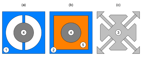
| Material | Density (kg/m3) | Young’s Mod. (MPa) | Poisson’s ratio |
| (1) Nylon | 1100 | 2000 | 0.4 |
| (2) Epoxy | 1180 | 4350 | 0.368 |
| (3) PA 11 | 1050 | 1800 | 0.405 |
| (4) Steel | 7800 | 180000 | 0.33 |
| (5) Silicone rubber | 1300 | 0.1175 | 0.469 |
- (2) The unit cell contains some kind of resonating element. These resonating elements are what cause the internal resonance modes that trigger the local resonance effects at a specified frequency. To achieve this, one can combine materials with different properties (preferably compliant materials assuming the role of springs and dense inclusions to act as masses) and/or rely on specific topologies that produce the same effects.
In Fig. 7, different LRAM-based unit cell configurations considered in this work are depicted. Each one employs a different strategy to achieve the local resonance effects expected.
3.1.5.1Homogenized macroscale model to study local resonance effects
In order to analyze the behavior of LRAMs and provide a better understanding of the bandgap formation mechanisms due to local resonance effects, an analytical treatment of Eq. (17) will be performed.
To do so, Eq. (17) will be solved in the frequency domain, for a given frequency , allowing us to condense the system by establishing the following relation:
|
|
(18) |
Substituting Eq. (18) into the expression for the inertial force density (given by Eq. (16)) allows us to determine an effective density tensor,
|
|
(19) |
where is the identity tensor.
For the sake of simplicity, let us assume plane wave propagation at a given frequency and wavenumber . Then
|
|
(20) |
where is the wave amplitude and is a unit vector with the wave propagation direction. In this context,
|
|
(21) | |
|
|
(22) |
Upon substitution of Eqs. (21) and (22) into Eq. (17), one gets the following dispersion relation
|
|
(23) |
To further simplify the analysis, let us consider a wave propagating in the -direction, i.e. , and a single vibration mode arising from the microscale causing local resonance effects only in the direction of the wave propagation, i.e. . In this regard, assuming the effective metamaterial has a standard linear elastic behavior, one gets three eigenvalues and eigenvectors from Eq. (23), namely
|
|
(24) |
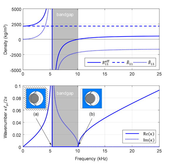
Note that and , which are associated to transverse propagation modes ( and are normal to the wave propagation direction ), have a standard dispersion relation proportional to the frequency through a constant propagation speed. However, for longitudinal waves the material is dispersive, as the relation between and is not linear due to the presence of local resonance effects caused by non-null values of . A close inspection on this expression allows us to realize: (1) as approaches the natural frequency , the corresponding effective density tensor term which causes ; and (2) when surpasses the value of , then (i.e. the metamaterial exhibits negative density-like behavior) causing to be purely imaginary (see Fig. 8 for an illustrative example).
According to Eq. (20), a purely imaginary wavenumber causes an effective attenuation of the wave’s amplitude as it propagates, producing the so-called frequency bandgap. This bandgap region is extended until a frequency that makes the corresponding effective density tensor component become null, . In Article I, it is demonstrated that these frequencies correspond to resonance frequencies for vibration modes in the unrestricted microscale inertial system.
3.1.5.2 Transmission loss in LRAM-based panels
The LRAM application considered throughout this work is the design of noise insulation panels with enhanced attenuating capabilities (due to local resonance effects) in a specified frequency range. These are typically in the low-frequency regime, where standard solutions would require the use of thick panels of dense materials.
The scheme in Fig. 9 is used to characterize the performance of such LRAM-based panels by computing their transmission loss as the ratio of the amplitudes of acoustic plane waves propagating normal to the panels’ surfaces on their front and rear sides. Details on this computation are provided in Article II.
This kind of example has also been used in Article I to validate the homogenization model through a comparison of the results obtained with a direct numerical simulation of the panel. The results of this study can be seen in Fig. 10.
3.2 Computational design of acoustic metamaterials
The homogenization framework presented can be employed to characterize the behavior of LRAMs. This motivates its use in the design process of such metamaterials aiming, for instance, at enhancing its attenuating capabilities. In this context, the application devised for LRAMs is in the form of noise insulation panels as described in Section 3.1.5.2. Therefore, since the levels of attenuation achieved by local resonance effects are large but very narrowband, the goal is to enlarge the effective frequency bandgap. In this regard, three different strategies have been considered: (1) stacking layers with different LRAM unit cell configurations aiming at overlapping their effective bandgaps, (2) taking advantage of the viscoelastic behavior of certain materials which, in combination with local resonance effects, can give rise to a damping emergence phenomenon called metadamping and (3) use topology optimization techniques to obtain unit cell designs with a targeted frequency range of operation and optimal (maximized) bandwidth.
3.2.1 Multi-layer LRAM-based panel design
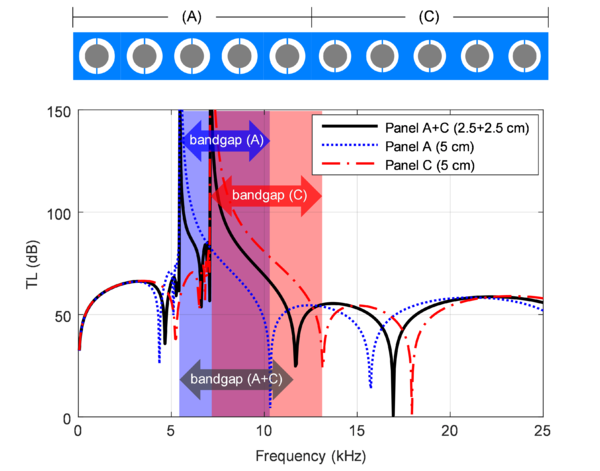
As a first approach in LRAMs design, the consideration of a multi-layered panel has been studied. The idea in this case is to enlarge the effective attenuation band (defined as the frequency range with transmission loss levels over a certain baseline value) by using different unit cell configurations in each layer, with overlapping frequency bandgaps. This concept has been explored using the proposed homogenization scheme as part of the examples section in Article I. An adaptation of these results (in terms of transmission loss) can be seen in Fig. 11.
First, it should be noted that the two overlapping bandgaps are produced with small changes in the geometrical properties of each unit cell. In this case, a simple reduction of 0.25 mm in the outer hole diameter (see Fig. 7-(a)) is enough to slightly increase the frequency bandgap width and move it to a 2 kHz higher frequency range.
The main drawback observed with this design concept is that, while the corresponding unit cells’ bandgaps overlap, the resulting transmission loss curve is not capable of producing a continuous effective attenuation band throughout the entire expected enlarged frequency bandgap. This is because by stacking layers with different unit cell configurations, they interact with each other producing undesired transmission (inverted) peaks at frequencies inside the attenuation region.
3.2.2 Introduction of damping effects
Viscoelastic behavior of materials can be accounted for in the proposed formulation by considering, on the microscale, a stress-strain relation of the form
|
|
(25) |
so that the stress tensor gains a strain-rate, , dependency through a fourth-order viscous tensor . First, it should be noted that the introduction of this additional term in the formulation does not affect the simplifying hypotheses considered for the application of the model to acoustic metamaterials problems. Details on the whole derivation of the model with viscoelastic effects can be found in Article II. Here, only the major implications of the changes in the results will be discussed:
- (1) While the assumption considered for the quasi-static subsystem still holds, some changes need to be applied to accommodate the presence of dissipation terms. Ultimately, this affects the expression obtained for the effective macroscopic stress, that now reads
|
|
(26) |
In contrast to the previous definition, given by Eq. (10), in this case a new term arises accounting for an effective viscous tensor, , responsible for relating the macroscopic stress with the strain-rate, .
- (2) Another difference appearing as a result of considering viscoelastic effects concerns the inertial subsystem. In this case, the expression for the macroscopic inertial force density remains the same as in Eq. (16), but an additional dissipation term appears in the reduced microscale system:
|
|
(27) |
where former Eq. (15) in its matrix form has been considered, i.e. with being a diagonal matrix containing all the relevant squared natural frequencies, denoting a column vector with the modal amplitudes and referring to a matrix containing the coupling vectors. In Eq. (27), is the new term assuming the role of a damping matrix.
Regarding Eq. (27), it should be noted that the addition of damping counteracts the beneficial effects of local resonance phenomena. However, in a low-frequency regime, depending on the level of viscosity, it can slightly extend the effective attenuation band. Another issue concerning the modal-based reduction is that, unlike the former microscale system from Eq. (15), the new system in Eq. (27) is not necessarily uncoupled, since is not diagonal, in general. This may cause the reduction scheme to not be so efficient, as additional modal amplitudes may be required in order to achieve more accurate results. While this issue is something that needs to be considered, in practice, it has been verified that it does not have a major impact on the overall formulation, because the degree of coupling is so small that good results can still be obtained considering only the relevant modes selected using the criterion established in Section 3.1.4 .
3.2.3 Topology optimization of LRAMs
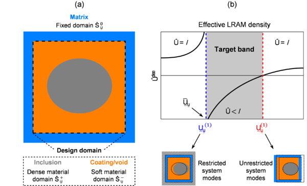
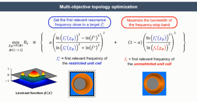
A LRAMs computational design methodology based on a level-set topology optimization strategy has been devised. The objectives for this optimization problem are:
- (1) Fit the relevant resonance frequency triggering local resonance effects into a targeted range.
- (2) Maximize the bandwidth of the frequency bandgap associated to the previous resonance frequency.
To do so, a smooth level-set function is defined to determine the material distribution by means of a characteristic function
|
|
(28) |
This characteristic function takes values of 1 for dense material regions (these will correspond to the resonating elements, i.e. the inclusions) and values of 0 for compliant material regions (which will be treated as void or coating materials). In this context, the level-set function becomes the unknown of the problem of minimizing the cost function, given by
|
|
(29) |
with
|
|
(30) | |
|
|
(31) |
In Eqs. (29)-(31), is a weighting parameter ( ) and is the squared target frequency where we expect to obtain local resonance effects. The variables and are the first relevant resonance frequencies for the restricted and unrestricted microscale inertial systems, respectively, which typically determine the lower and upper bounds of the associated frequency bandgap. Thus, at each iteration step, the following equations must be satisfied:
|
|
(32) | |
|
|
(33) |
It should be noted that the objective function is bounded between 0 and 1 and is composed by two subfunctions, and . The former (see Eq. (30)) reaches its minimum when the squared first relevant resonance frequency of the restricted system (i.e. the one producing local resonance effects) matches the targeted one , satisfying the first objective established. As for the latter (see Eq. (31)), its value decreases as the difference between and becomes larger (i.e. the frequency bandgap limits extend, which satisfies the second objective set).
To solve the problem, a pseudo-time variable is used to update the solution, starting from an initial state that consist of the design area filled entirely with dense material (i.e. in the whole domain), until it reaches an appropriate converged solution. A Hamilton-Jacobi approach has been considered, where the updated solution is given by
|
|
(34) |
with being a time-step, is an adjusting parameter and is the so-called topological sensitivity of the cost function (also known as the variational topological derivative of the functional ). Details on the derivation of can be found in Article II.
Some important aspects concerning the topology optimization problem devised include:
- (1) To ensure the appearance of a topological design that triggers local resonance effects, the target squared frequency needs to be set in a proper region that is typically determined by the dimensions of the unit cell, for a given set of material properties. This also implies that , i.e. the frequency fitting must be part of the objective function always.
- (2) The design domain is surrounded by a fixed material frame, which is considered infinitely stiff so that no deformation modes appear in the modal analysis. This is done also to avoid spurious interactions of the matrix with the inclusion/coating materials considered for the topological design area in the early steps of the algorithm.
- (3) The mass of the void/coating material is neglected, again, to avoid spurious modes that would difficult the proper identification of the relevant resonance mode. This should not affect the value of the resonance frequency, since the parameters that play a role in its determination are the elastic properties of the coating phase and the mass of the inclusion, both of which remain unaltered with this assumption.
- (4) Finally, in order to help the algorithm become more stable, only the degrees of freedom in the direction where one expects local resonance effects to arise are left free (assuming the unit cell will work as a LRAM panel subjected to plane waves propagating in the predefined direction, this simplification is not a cause for important issues from the topological design point of view).
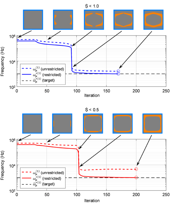
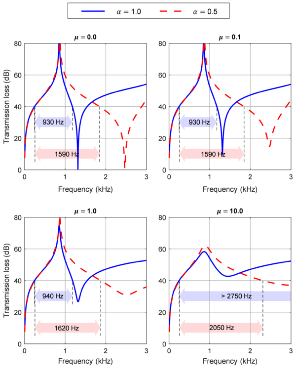
In Fig. 13, an example from Article II of the application of the proposed topological design strategy is shown. For comparison, two cases have been studied: one only accounting for the frequency fitting ( 1) to get a topology with an internal resonance frequency in a target value, and another in which bandgap maximization is also taken into account ( 0.5). Notice the big jump in the resonance frequency scale once the inclusion gets detached from the matrix. The corresponding transmission loss curves for each case are given in Fig. 14, which can be found also in Article II. In this case, one can also see the smoothing effect caused by increasing the viscosity of the coating material upon considering viscoelastic behavior in the model, which translates in slightly wider bandgaps. This, combined with topological optimized designs, lead to big improvements in the attenuation properties of the LRAM panel.
3.3 Experimental validation
The last main contribution of this work involves a series of experimental tests with the following objectives: (1) to demonstrate the concept of local resonance and show its effects on a fully 3D-printed acoustic metamaterial prototype and (2) validate the computational framework developed to characterize them. A detailed description of the experiments carried out and the obtained results can be found in Article III. Here, some important aspects will be highlighted.
3.3.1 Prototypes design
For almost 20 years, there have been plenty of acoustic metamaterials realizations that have been tested experimentally. While most of them are based on local resonance as the mechanism responsible for their attenuating properties, they differ in the way this kind of phenomenon is achieved. For a review on the different concepts and designs found in the literature, the reader is referred to Section 2.3 of this work. Most of the early designs employed composite structures composed of different material phases in order to obtain the desired properties. These designs are effective and capable of exhibiting local resonance effects, but they are not practical, mainly because of manufacturability issues or the dimensions required.
In this context, the prototypes for the devised set of experimental tests are designed with the notion of making them practical. To do so, given the recent growth and potential of new additive manufacturing technologies, the acoustic metamaterials employed as prototypes have been designed so that they can be fully 3D-printed via multi jet fusion (MJF) techniques. The main challenge when choosing 3D-printing as the fabrication method is in the currently available materials. In order to target the interesting frequency range of operation for sound insulation applications (around and below 1000 Hz), the materials employed need to allow internal resonances in this low-frequency regime, which typically implies the combination of highly compliant and dense materials. Since the majority of materials used in 3D-printing are polymers, the aforementioned frequency range is difficult to achieve with a set of dimensions that makes the metamaterial attractive for practical purposes, i.e. thin and lightweight, and at the same time, respect the limits and tolerances set by the manufacturing system. Here is where the unit cell design plays an important role, since it can be exploited to obtain the desired properties, subjected to the material restrictions, and be interesting from a practical point of view.
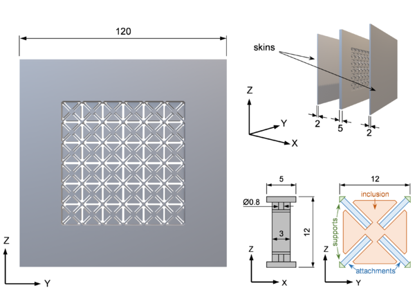
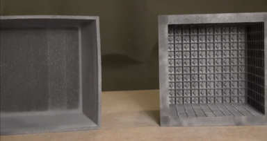
To this end, the prototype built for the experimental tests consists of a panel with a thickness of only 5 mm and composed of unit cells with the design shown in Fig. 13. The material employed is a Polyamide (PA11), with a density of 1050 kg/m3, a Young’s modulus of 1800 MPa and a Poisson’s ratio of 0.405. The unit cell design has been carefully chosen so that it can be easily 3D-printed from a single block of material, while still having the required elements for local resonance effects to arise. In particular, (1) the support rods at the unit cell’s vertices act as fixing points to isolate each unit cell and trigger the appearance of internal resonance modes; (2) the central inclusion provides the mass for the resonating element, and (3) the thin attachments connecting the inclusion to the supports assume the role of springs, allowing the unit cell to have relevant resonance modes in the desired frequency range, around 1000 Hz. In fact, in order to achieve this frequency range, the particular flower-like topology has been chosen so that the bending stiffness of the attachments is small (which is attained with longer elements) and the resonating mass is as big as possible (by occupying most of the space available).
3.3.2 Impedance tube measurements
Impedance tubes are used to characterize the acoustic performance of materials, in particular, its transmission and reflection coefficients to normal incidence plane waves. The device employed to carry out such kind of experimental tests in the present work consists of two tube parts built with medium-density fiberboard 4 cm thick, with a squared section of 8 cm x 8 cm. A 3.3 inch loudspeaker (4 Ohm, 30 W) is connected to an amplifier and located on one end of the first tube. The other tube’s termination is filled with a polyurethane foam to act as an absorbing material, which guarantees an anechoic condition (no reflections). Four 1/2 inch prepolarized microphones with an integrated circuit piezoelectric preamplifier are positioned at different tube sections (see Fig. 14).
The guidelines from ASTM E1050-98 have been followed in order to set the section size and microphone separation to guarantee a frequency range of operation between 200 and 2000 Hz. Assuming plane wave propagation in this range, the following expressions can be used to describe the pressure field in the front () and rear () tube sections in the frequency domain:
|
|
(35) | |
|
|
(36) |
where refers to the longitudinal position in the tube with respect to the sample’s incident surface section, is the frequency, is the wavenumber (which is related to the speed of sound in air, , by ) and , and are the incident, reflected and transmitted wave’s amplitude coefficients, respectively.
Note that reflections on the rear sections of the tube are being neglected here because of the anechoic termination. With measurements of the pressure field on the four microphone positions, one can easily obtain the values for these coefficients and compute the transmission loss as
|
|
(37) |
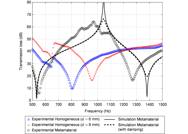
The results of these measurements for the 3D-printed prototype panel can be observed in Fig. 17 (also in Article III), along with the transmission loss computation from a simulated panel where the proposed homogenization scheme has been applied. The metamaterial case shows increased attenuation around the expected frequency when compared to equivalent homogeneous panels with the same thickness and equivalent mass.
Chapter 4
CONCLUSIONS
4.1 Discussion of the results
By applying the concepts of multiscale homogenization, model-order reduction techniques and topology optimization, a set of computational tools has been developed to study and design acoustic metamaterials. The numerical framework proposed highlights the potential of the computational design of materials and its ability to characterize complex material behavior, such as local resonance effects. The key aspects developed throughout the present thesis are discussed here:
- (1) Multiscale homogenization of acoustic metamaterials. A general multiscale homogenization framework capable of accounting for inertial effects has been built upon the so-called multiscale virtual power principle. The macroscale (part) is linked to the microscale (metamaterial) through a kinematic relation and a Lagrange-based form of the energetic equivalence between both scales provides a good setting for solving the problem in the microscale and identifying the Lagrange multipliers as the macroscopic effective stress and inertial force density terms. Based on (a) the separation of scales condition ( ) and assuming (b) a density distribution symmetrical with respect to each unit cell’s center, along with (c) neglecting body forces, the formulation can be simplified to characterize periodic arrangements of acoustic metamaterials. Namely, the microscale system can be split onto a quasi-static component, from which an effective constitutive tensor is obtained, and an inertial component, from which the effective inertial force density is derived as a function of the macroscopic acceleration and some micro-inertial terms accounting for local resonance effects.
- (2) Modal-based model-order reduction accounting for internal resonances. By solving the eigenproblem in the microscale inertial subsystem, one can identify the relevant internal resonance modes responsible for triggering local resonance effects on the macroscale. This is translated in a huge reduction of the computational effort required to solve the coupling between the macro and microscales due to inertial effects, while still allowing the model to properly capture the acoustic metamaterials’ behavior.
- (3) Topology optimization for frequency bandgap fitting and maximization. A level-set optimization algorithm is used to obtain acoustic metamaterial unit cell’s designs that allow to (a) set the target frequency range where local resonance effects are expected to arise, and (b) maximize the effective frequency bandgap along with the attenuation performance for panel-based applications subject to normal incident acoustic plane waves.
- (4) Damping phenomena accounting for more realistic material behavior. The homogenization framework has been enriched with the incorporation of more realistic material behavior in the microscale by accounting for viscoelastic effects. This addition has allowed to study the impacts of damping in acoustic metamaterials and, more specifically, its role when used in combination with local resonance effects.
- (5) Experimental validation with 3D-printed prototypes. Aiming at experimentally demonstrating the effects of local resonance phenomena of acoustic metamaterials, an impedance tube-based test has been devised to analyze the transmission loss of panels subject to normal-incidence acoustic plane waves. These experiments have been used to both validate the homogenization model and to prove the enhanced attenuating capabilities of acoustic metamaterials based on a fully 3D-printed design.
The model has been successfully applied to simulate the attenuating capabilities of LRAM-based panels subject to normal-incidence acoustic plane waves. Such example has been considered to validate the homogenization framework through comparison with a direct numerical simulation. The results confirm the applicability range of the model within the simplifying hypotheses considered and prove the effectiveness of the modal-based reduction strategy by achieving reductions of up to 0.1% of the total number of degrees of freedom of the problem (in a 2D setting) while still managing to obtain accurate results with < 1% of relative error in the frequency range of interest.
Using the computational tools developed in this work, early attempts at designing LRAM-based panels for sound insulation in a low-frequency range (around 1 kHz) have been carried out, following different approaches:
- (1) In Article I, the idea of combining multiple layers with different unit cell designs (each one providing a frequency bandgap in different overlapping regions) has been explored. The aim is to obtain an extended effective attenuation band by taking advantage of multiple internal resonances. The preliminary study performed reveals that there is still room for improvement in this regard, especially in understanding the interaction between the different layers to get a continuous attenuation band.
- (2) In Article II, the topology optimization algorithm has been used to set the local resonance effects in a targeted frequency around 1 kHz. Designs with bandgap maximization as part of the cost function in the optimization algorithm have been obtained and proven to almost double the frequency bandgap compared to non-optimized designs. This translates in an increase of more than 1.5 times the bandwidth of effective continuous attenuation over 40 dB. Furthermore, the consideration of viscoelastic effects in the coating material phase has also shown that this effective bandwidth can be extended an additional 30%.
- (3) In Article III, the first attempt at building a practical acoustic metamaterial prototype by employing a currently available 3D-printing technology has been carried out. Its design has been devised to get local resonance effects in a frequency range around 1 kHz with a set of dimensions that make it both interesting for practical applications and manufacturable within the 3D-printing technology limitations. To do so, the design consists of a flower-like shaped inclusion in order to maximize the resonating mass, while still allowing the presence of thin attachments (acting as springs) long enough to produce internal resonances in the frequency range of interest.
4.2 Future research lines
All the developments and results achieved throughout the present work can be regarded as the foundation for further research lines related to the design and characterization of acoustic metamaterials. Some of these possible research topics are discussed here:
- (1) Similar to how viscoelastic effects have been introduced in the model in order to account for more realistic behavior, other kind of phenomena can also be added to the present formulation in order to enrich it. In this context, the consideration of non-linear material behavior could be an example. Another possibility would be to extend the range of applicability of the model to higher frequency ranges by incorporating Bloch-Floquet conditions. This would allow the model to be used, for instance, in characterizing the behavior of phononic crystal structures.
- (2) The topology optimization algorithm presented is also subject to be updated (for example, with new cost functions or restrictions) to obtain more efficient designs that are feasible and practical in terms of manufacturability. This would also offer the possibility of building prototypes to experimentally test and validate the benefits attained with the design optimization.
- (3) Although the proposed model is specifically tailored for the study of acoustic metamaterials, given the similarity between such kind of metamaterials with others (in electromagnetic applications, for instance), another possible research line devised is the adaptation of the framework to these other types of metamaterials.
References
[1] T. J. Cui, D. R. Smith, and R. Liu, “Introduction to Metamaterials,” in Metamaterials, Springer, 2010, pp. 1–19.
[2] W. E. Kock, “Metallic Delay Lenses,” Bell Syst. Tech. J., vol. 27, no. 1, pp. 58–82, Jan. 1948, doi: http://dx.doi.org/10.1002/j.1538-7305.1948.tb01331.x.
[3] V. G. Veselago, “The electrodynamics of substances with simultaneously negative values of ϵ and μ,” Sov. Phys. Uspekhi, vol. 10, no. 4, pp. 509–514, Apr. 1968, doi:
http://dx.doi.org/10.1070/PU1968v010n04ABEH003699.
[4] D. R. Smith, W. J. Padilla, D. C. Vier, S. C. Nemat-Nasser, and S. Schultz, “Composite Medium with Simultaneously Negative Permeability and Permittivity,” Phys. Rev. Lett., vol. 84, no. 18, pp. 4184–4187, May 2000, doi:
http://dx.doi.org/10.1103/PhysRevLett.84.4184.
[5] J. B. Pendry, A. J. Holden, D. J. Robbins, and W. J. Stewart, “Magnetism from conductors and enhanced nonlinear phenomena,” IEEE Trans. Microw. Theory Tech., vol. 47, no. 11, pp. 2075–2084, 1999, doi:
http://dx.doi.org/10.1109/22.798002.
[6] P. A. Deymier, “Introduction to Phononic Crystals and Acoustic Metamaterials,” in Acoustic metamaterials and phononic crystals, vol. 173, Springer Science & Business Media, 2013, pp. 1–12.
[7] M. I. Hussein, M. J. Leamy, and M. Ruzzene, “Dynamics of Phononic Materials and Structures: Historical Origins, Recent Progress, and Future Outlook,” Appl. Mech. Rev., vol. 66, no. 4, p. 040802, Jul. 2014, doi: http://dx.doi.org/10.1115/1.4026911.
[8] T.-T. Wu, Y.-T. Chen, J.-H. Sun, S.-C. S. Lin, and T. J. Huang, “Focusing of the lowest antisymmetric Lamb wave in a gradient-index phononic crystal plate,” Appl. Phys. Lett., vol. 98, no. 17, p. 171911, Apr. 2011, doi:
http://dx.doi.org/10.1063/1.3583660.
[9] S. Gonella, A. C. To, and W. K. Liu, “Interplay between phononic bandgaps and piezoelectric microstructures for energy harvesting,” J. Mech. Phys. Solids, vol. 57, no. 3, pp. 621–633, Mar. 2009, doi:
http://dx.doi.org/10.1016/j.jmps.2008.11.002.
[10] P. E. Hopkins et al., “Reduction in the Thermal Conductivity of Single Crystalline Silicon by Phononic Crystal Patterning,” Nano Lett., vol. 11, no. 1, pp. 107–112, Jan. 2011, doi: http://dx.doi.org/10.1021/nl102918q.
[11] Y. Pennec et al., “Simultaneous existence of phononic and photonic band gaps in periodic crystal slabs,” Opt. Express, vol. 18, no. 13, p. 14301, Jun. 2010, doi:
http://dx.doi.org/10.1364/OE.18.014301.
[12] O. Guasch, P. Sánchez-Martín, and D. Ghilardi, “Application of the transfer matrix approximation for wave propagation in a metafluid representing an acoustic black hole duct termination,” Appl. Math. Model., vol. 77, pp. 1881–1893, Jan. 2020, doi:
http://dx.doi.org/10.1016/j.apm.2019.09.039.
[13] J. Deng, O. Guasch, and L. Zheng, “Ring-shaped acoustic black holes for broadband vibration isolation in plates,” J. Sound Vib., vol. 458, pp. 109–122, Oct. 2019, doi: http://dx.doi.org/10.1016/j.jsv.2019.06.017.
[14] Z. Liu et al., “Locally Resonant Sonic Materials,” Science (80-. )., vol. 289, no. 5485, pp. 1734–1736, Sep. 2000, doi:
http://dx.doi.org/10.1126/science.289.5485.1734.
[15] K. M. Ho, C. K. Cheng, Z. Yang, X. X. Zhang, and P. Sheng, “Broadband locally resonant sonic shields,” Appl. Phys. Lett., vol. 83, no. 26, pp. 5566–5568, Dec. 2003, doi: http://dx.doi.org/10.1063/1.1637152.
[16] C.-L. Ding and X.-P. Zhao, “Multi-band and broadband acoustic metamaterial with resonant structures,” J. Phys. D. Appl. Phys., vol. 44, no. 21, p. 215402, Jun. 2011, doi: http://dx.doi.org/10.1088/0022-3727/44/21/215402.
[17] M. Ambati, N. Fang, C. Sun, and X. Zhang, “Surface resonant states and superlensing in acoustic metamaterials,” Phys. Rev. B, vol. 75, no. 19, p. 195447, May 2007, doi: http://dx.doi.org/10.1103/PhysRevB.75.195447.
[18] S. Guenneau, A. Movchan, G. Pétursson, and S. Anantha Ramakrishna, “Acoustic metamaterials for sound focusing and confinement,” New J. Phys., vol. 9, no. 11, pp. 399–399, Nov. 2007, doi: http://dx.doi.org/10.1088/1367-2630/9/11/399.
[19] J. Zhu et al., “A holey-structured metamaterial for acoustic deep-subwavelength imaging,” Nat. Phys., vol. 7, no. 1, pp. 52–55, Jan. 2011, doi:
http://dx.doi.org/10.1038/nphys1804.
[20] J. B. Pendry and J. Li, “An acoustic metafluid: realizing a broadband acoustic cloak,” New J. Phys., vol. 10, no. 11, p. 115032, Nov. 2008, doi:
http://dx.doi.org/10.1088/1367-2630/10/11/115032.
[21] S. A. Cummer and D. Schurig, “One path to acoustic cloaking,” New J. Phys., vol. 9, no. 3, pp. 45–45, Mar. 2007, doi: http://dx.doi.org/10.1088/1367-2630/9/3/045.
[22] H. Chen and C. T. Chan, “Acoustic cloaking in three dimensions using acoustic metamaterials,” Appl. Phys. Lett., vol. 91, no. 18, p. 183518, Oct. 2007, doi:
http://dx.doi.org/10.1063/1.2803315.
[23] A. N. Norris, “Acoustic metafluids,” J. Acoust. Soc. Am., vol. 125, no. 2, pp. 839–849, Feb. 2009, doi: http://dx.doi.org/10.1121/1.3050288.
[24] R. Hill, “A self-consistent mechanics of composite materials,” J. Mech. Phys. Solids, vol. 13, no. 4, pp. 213–222, Aug. 1965, doi:
http://dx.doi.org/10.1016/0022-5096(65)90010-4.
[25] J. Mandel, Plasticite classique et viscoplasticite. Springer, 1971.
[26] F. Feyel and J.-L. Chaboche, “FE2 multiscale approach for modelling the elastoviscoplastic behaviour of long fibre SiC/Ti composite materials,” Comput. Methods Appl. Mech. Eng., vol. 183, no. 3–4, pp. 309–330, Mar. 2000, doi:
http://dx.doi.org/10.1016/S0045-7825(99)00224-8.
[27] V. Kouznetsova, W. A. M. Brekelmans, and F. P. T. Baaijens, “Approach to micro-macro modeling of heterogeneous materials,” Comput. Mech., vol. 27, no. 1, pp. 37–48, 2001, doi: http://dx.doi.org/10.1007/s004660000212.
[28] C. V. Verhoosel, J. J. C. Remmers, and M. A. Gutiérrez, “A partition of unity-based multiscale approach for modelling fracture in piezoelectric ceramics,” Int. J. Numer. Methods Eng., vol. 82, no. 8, pp. 966–994, Dec. 2009, doi:
http://dx.doi.org/10.1002/nme.2792.
[29] V. Phu Nguyen, O. Lloberas-Valls, M. Stroeven, and L. Johannes Sluys, “On the existence of representative volumes for softening quasi-brittle materials – A failure zone averaging scheme,” Comput. Methods Appl. Mech. Eng., vol. 199, no. 45–48, pp. 3028–3038, Nov. 2010, doi: http://dx.doi.org/10.1016/j.cma.2010.06.018.
[30] J. Oliver, M. Caicedo, E. Roubin, A. E. Huespe, and J. A. Hernández, “Continuum approach to computational multiscale modeling of propagating fracture,” Comput. Methods Appl. Mech. Eng., vol. 294, pp. 384–427, Sep. 2015, doi:
http://dx.doi.org/10.1016/j.cma.2015.05.012.
[31] I. Özdemir, W. A. M. Brekelmans, and M. G. D. Geers, “Computational homogenization for heat conduction in heterogeneous solids,” Int. J. Numer. Methods Eng., vol. 73, no. 2, pp. 185–204, Jan. 2008, doi:
http://dx.doi.org/10.1002/nme.2068.
[32] V. Kouznetsova, M. G. D. Geers, and W. A. M. Brekelmans, “Multi-scale constitutive modelling of heterogeneous materials with a gradient-enhanced computational homogenization scheme,” Int. J. Numer. Methods Eng., vol. 54, no. 8, pp. 1235–1260, Jul. 2002, doi: http://dx.doi.org/10.1002/nme.541.
[33] A. Karamnejad, V. P. Nguyen, and L. J. Sluys, “A multi-scale rate dependent crack model for quasi-brittle heterogeneous materials,” Eng. Fract. Mech., vol. 104, pp. 96–113, May 2013, doi: http://dx.doi.org/10.1016/j.engfracmech.2013.03.009.
[34] K. Pham, V. G. Kouznetsova, and M. G. D. Geers, “Transient computational homogenization for heterogeneous materials under dynamic excitation,” J. Mech. Phys. Solids, vol. 61, no. 11, pp. 2125–2146, Nov. 2013, doi:
http://dx.doi.org/10.1016/j.jmps.2013.07.005.
[35] E. A. de Souza Neto, P. J. Blanco, P. J. Sánchez, and R. A. Feijóo, “An RVE-based multiscale theory of solids with micro-scale inertia and body force effects,” Mech. Mater., vol. 80, no. Part A, pp. 136–144, Jan. 2015, doi:
http://dx.doi.org/10.1016/j.mechmat.2014.10.007.
[36] P. J. Blanco, P. J. Sánchez, E. A. de Souza Neto, and R. A. Feijóo, “Variational Foundations and Generalized Unified Theory of RVE-Based Multiscale Models,” Arch. Comput. Methods Eng., vol. 23, no. 2, pp. 191–253, Jun. 2016, doi:
http://dx.doi.org/10.1007/s11831-014-9137-5.
[37] A. Chatterjee, “An introduction to the proper orthogonal decomposition,” Curr. Sci., vol. 78, no. 7, pp. 808–817, 2000.
[38] P. Krysl, S. Lall, and J. E. Marsden, “Dimensional model reduction in non‐linear finite element dynamics of solids and structures,” Int. J. Numer. Methods Eng., vol. 51, no. 4, pp. 479–504, Jun. 2001, doi: http://dx.doi.org/10.1002/nme.167.
[39] T. W. McDevitt, G. M. Hulbert, and N. Kikuchi, “An assumed strain method for the dispersive global–local modeling of periodic structures,” Comput. Methods Appl. Mech. Eng., vol. 190, no. 48, pp. 6425–6440, Sep. 2001, doi:
http://dx.doi.org/10.1016/S0045-7825(00)00184-5.
[40] M. I. Hussein and G. M. Hulbert, “Mode-enriched dispersion models of periodic materials within a multiscale mixed finite element framework,” Finite Elem. Anal. Des., vol. 42, no. 7, pp. 602–612, Apr. 2006, doi:
http://dx.doi.org/10.1016/j.finel.2005.11.002.
[41] M. P. Bendsøe and N. Kikuchi, “Generating optimal topologies in structural design using a homogenization method,” Comput. Methods Appl. Mech. Eng., vol. 71, no. 2, pp. 197–224, Nov. 1988, doi: http://dx.doi.org/10.1016/0045-7825(88)90086-2.
[42] M. P. Bendsøe, “Optimal shape design as a material distribution problem,” Struct. Optim., vol. 1, no. 4, pp. 193–202, Dec. 1989, doi:
http://dx.doi.org/10.1007/BF01650949.
[43] P. Duysinx and M. P. Bendsøe, “Topology optimization of continuum structures with local stress constraints,” Int. J. Numer. Methods Eng., vol. 43, no. 8, pp. 1453–1478, Dec. 1998, doi: http://dx.doi.org/10.1002/(SICI)1097-0207(19981230)43:8<1453::AID-NME480>3.0.CO;2-2.
[44] M. P. Bendsøe and O. Sigmund, Topology Optimization. Berlin, Heidelberg: Springer Berlin Heidelberg, 2004.
[45] O. Sigmund, “On the Design of Compliant Mechanisms Using Topology Optimization*,” Mech. Struct. Mach., vol. 25, no. 4, pp. 493–524, Jan. 1997, doi:
http://dx.doi.org/10.1080/08905459708945415.
[46] T. Buhl, C. B. W. Pedersen, and O. Sigmund, “Stiffness design of geometrically nonlinear structures using topology optimization,” Struct. Multidiscip. Optim., vol. 19, no. 2, pp. 93–104, Apr. 2000, doi: http://dx.doi.org/10.1007/s001580050089.
[47] O. Sigmund, “Design of multiphysics actuators using topology optimization – Part I: One-material structures,” Comput. Methods Appl. Mech. Eng., vol. 190, no. 49–50, pp. 6577–6604, Oct. 2001, doi:
http://dx.doi.org/10.1016/S0045-7825(01)00251-1.
[48] J. S. Jensen and O. Sigmund, “Systematic design of photonic crystal structures using topology optimization: Low-loss waveguide bends,” Appl. Phys. Lett., vol. 84, no. 12, pp. 2022–2024, Mar. 2004, doi: http://dx.doi.org/10.1063/1.1688450.
[49] O. Sigmund and J. Søndergaard Jensen, “Systematic design of phononic band–gap materials and structures by topology optimization,” Philos. Trans. R. Soc. London. Ser. A Math. Phys. Eng. Sci., vol. 361, no. 1806, pp. 1001–1019, May 2003, doi: http://dx.doi.org/10.1098/rsta.2003.1177.
[50] H. A. Eschenauer, V. V. Kobelev, and A. Schumacher, “Bubble method for topology and shape optimization of structures,” Struct. Optim., vol. 8, no. 1, pp. 42–51, Aug. 1994, doi: http://dx.doi.org/10.1007/BF01742933.
[51] J. Sokolowski and A. Zochowski, “On the Topological Derivative in Shape Optimization,” SIAM J. Control Optim., vol. 37, no. 4, pp. 1251–1272, Jan. 1999, doi: http://dx.doi.org/10.1137/S0363012997323230.
[52] S. J. Osher and F. Santosa, “Level Set Methods for Optimization Problems Involving Geometry and Constraints,” J. Comput. Phys., vol. 171, no. 1, pp. 272–288, Jul. 2001, doi: http://dx.doi.org/10.1006/jcph.2001.6789.
[53] G. Allaire, F. Jouve, and A.-M. Toader, “Structural optimization using sensitivity analysis and a level-set method,” J. Comput. Phys., vol. 194, no. 1, pp. 363–393, Feb. 2004, doi: http://dx.doi.org/10.1016/j.jcp.2003.09.032.
[54] S. Amstutz and H. Andrä, “A new algorithm for topology optimization using a level-set method,” J. Comput. Phys., vol. 216, no. 2, pp. 573–588, Aug. 2006, doi:
http://dx.doi.org/10.1016/j.jcp.2005.12.015.
[55] S. M. Giusti, A. A. Novotny, and C. Padra, “Topological sensitivity analysis of inclusion in two-dimensional linear elasticity,” Eng. Anal. Bound. Elem., vol. 32, no. 11, pp. 926–935, Nov. 2008, doi:
http://dx.doi.org/10.1016/j.enganabound.2007.12.007.
[56] J. Oliver, D. Yago, J. Cante, and O. Lloberas-Valls, “Variational approach to relaxed topological optimization: Closed form solutions for structural problems in a sequential pseudo-time framework,” Comput. Methods Appl. Mech. Eng., vol. 355, pp. 779–819, Oct. 2019, doi: http://dx.doi.org/10.1016/j.cma.2019.06.038.
[57] D. Yago, J. Cante, O. Lloberas-Valls, and J. Oliver, “Topology optimization of thermal problems in a nonsmooth variational setting: closed-form optimality criteria,” Comput. Mech., 2020, doi:
http://dx.doi.org/10.1007/s00466-020-01850-0.
[58] Y. Xiao, B. R. Mace, J. Wen, and X. Wen, “Formation and coupling of band gaps in a locally resonant elastic system comprising a string with attached resonators,” Phys. Lett. A, vol. 375, no. 12, pp. 1485–1491, Mar. 2011, doi:
http://dx.doi.org/10.1016/j.physleta.2011.02.044.
[59] L. Liu and M. I. Hussein, “Wave Motion in Periodic Flexural Beams and Characterization of the Transition Between Bragg Scattering and Local Resonance,” J. Appl. Mech., vol. 79, no. 1, p. 11003, Jan. 2012, doi:
http://dx.doi.org/10.1115/1.4004592.
[60] M. Moscatelli, R. Ardito, L. Driemeier, and C. Comi, “Band-gap structure in two- and three-dimensional cellular locally resonant materials,” J. Sound Vib., vol. 454, pp. 73–84, Aug. 2019, doi: http://dx.doi.org/10.1016/j.jsv.2019.04.027.
[61] M. I. Hussein, “Reduced Bloch mode expansion for periodic media band structure calculations,” Proc. R. Soc. A Math. Phys. Eng. Sci., vol. 465, no. 2109, pp. 2825–2848, Sep. 2009, doi: http://dx.doi.org/10.1098/rspa.2008.0471.
[62] V. Fokin, M. Ambati, C. Sun, and X. Zhang, “Method for retrieving effective properties of locally resonant acoustic metamaterials,” Phys. Rev. B, vol. 76, no. 14, p. 144302, Oct. 2007, doi: http://dx.doi.org/10.1103/PhysRevB.76.144302.
[63] S. Nemat-Nasser, J. R. Willis, A. Srivastava, and A. V Amirkhizi, “Homogenization of periodic elastic composites and locally resonant sonic materials,” Phys. Rev. B, vol. 83, no. 10, p. 104103, Mar. 2011, doi:
http://dx.doi.org/10.1103/PhysRevB.83.104103.
[64] A. Sridhar, V. G. Kouznetsova, and M. G. D. D. Geers, “Homogenization of locally resonant acoustic metamaterials towards an emergent enriched continuum,” Comput. Mech., vol. 57, no. 3, pp. 423–435, Mar. 2016, doi:
http://dx.doi.org/10.1007/s00466-015-1254-y.
[65] A. Sridhar, V. G. Kouznetsova, and M. G. D. Geers, “A semi-analytical approach towards plane wave analysis of local resonance metamaterials using a multiscale enriched continuum description,” Int. J. Mech. Sci., vol. 133, no. August, pp. 188–198, Nov. 2017, doi: http://dx.doi.org/10.1016/j.ijmecsci.2017.08.027.
[66] D. Roca, O. Lloberas-Valls, J. Cante, and J. Oliver, “A computational multiscale homogenization framework accounting for inertial effects: Application to acoustic metamaterials modelling,” Comput. Methods Appl. Mech. Eng., vol. 330, pp. 415–446, Mar. 2018, doi: http://dx.doi.org/10.1016/j.cma.2017.10.025.
[67] D. Roca, D. Yago, J. Cante, O. Lloberas-Valls, and J. Oliver, “Computational design of locally resonant acoustic metamaterials,” Comput. Methods Appl. Mech. Eng., vol. 345, pp. 161–182, Mar. 2019, doi:
http://dx.doi.org/10.1016/j.cma.2018.10.037.
[68] A. O. Krushynska, V. G. Kouznetsova, and M. G. D. Geers, “Towards optimal design of locally resonant acoustic metamaterials,” J. Mech. Phys. Solids, vol. 71, no. 1, pp. 179–196, Nov. 2014, doi: http://dx.doi.org/10.1016/j.jmps.2014.07.004.
[69] T. Matsuki, T. Yamada, K. Izui, and S. Nishiwaki, “Topology optimization for locally resonant sonic materials,” Appl. Phys. Lett., vol. 104, no. 19, p. 191905, May 2014, doi: http://dx.doi.org/10.1063/1.4878259.
[70] M. I. Hussein and M. J. Frazier, “Metadamping: An emergent phenomenon in dissipative metamaterials,” J. Sound Vib., vol. 332, no. 20, pp. 4767–4774, Sep. 2013, doi: http://dx.doi.org/10.1016/j.jsv.2013.04.041.
[71] M. J. Frazier and M. I. Hussein, “Viscous-to-viscoelastic transition in phononic crystal and metamaterial band structures,” J. Acoust. Soc. Am., vol. 138, no. 5, pp. 3169–3180, Nov. 2015, doi: http://dx.doi.org/10.1121/1.4934845.
[72] D. DePauw, H. Al Ba’ba’a, and M. Nouh, “Metadamping and energy dissipation enhancement via hybrid phononic resonators,” Extrem. Mech. Lett., vol. 18, pp. 36–44, Jan. 2018, doi: http://dx.doi.org/10.1016/j.eml.2017.11.002.
[73] J. M. Manimala and C. T. Sun, “Microstructural design studies for locally dissipative acoustic metamaterials,” J. Appl. Phys., vol. 115, no. 2, p. 023518, Jan. 2014, doi: http://dx.doi.org/10.1063/1.4861632.
[74] A. O. Krushynska, V. G. Kouznetsova, and M. G. D. Geers, “Visco-elastic effects on wave dispersion in three-phase acoustic metamaterials,” J. Mech. Phys. Solids, vol. 96, pp. 29–47, Nov. 2016, doi: http://dx.doi.org/10.1016/j.jmps.2016.07.001.
[75] M. A. Lewińska, V. G. Kouznetsova, J. A. W. van Dommelen, A. O. Krushynska, and M. G. D. Geers, “The attenuation performance of locally resonant acoustic metamaterials based on generalised viscoelastic modelling,” Int. J. Solids Struct., vol. 126–127, pp. 163–174, Nov. 2017, doi:
http://dx.doi.org/10.1016/j.ijsolstr.2017.08.003.
[76] O. R. Bilal and M. I. Hussein, “Trampoline metamaterial: Local resonance enhancement by springboards,” Appl. Phys. Lett., vol. 103, no. 11, p. 111901, Sep. 2013, doi: http://dx.doi.org/10.1063/1.4820796.
[77] P. Sheng, X. X. Zhang, Z. Liu, and C. T. Chan, “Locally resonant sonic materials,” Phys. B Condens. Matter, vol. 338, no. 1–4, pp. 201–205, Oct. 2003, doi: http://dx.doi.org/10.1016/S0921-4526(03)00487-3.
[78] G. Wang, X. Wen, J. Wen, L. Shao, and Y. Liu, “Two-Dimensional Locally Resonant Phononic Crystals with Binary Structures,” Phys. Rev. Lett., vol. 93, no. 15, p. 154302, Oct. 2004, doi: http://dx.doi.org/10.1103/PhysRevLett.93.154302.
[79] K. M. Ho, Z. Yang, X. X. Zhang, and P. Sheng, “Measurements of sound transmission through panels of locally resonant materials between impedance tubes,” Appl. Acoust., vol. 66, no. 7, pp. 751–765, Jul. 2005, doi:
http://dx.doi.org/10.1016/j.apacoust.2004.11.005.
[80] E. P. Calius, X. Bremaud, B. Smith, and A. Hall, “Negative mass sound shielding structures: Early results,” Phys. status solidi, vol. 246, no. 9, pp. 2089–2097, Sep. 2009, doi: http://dx.doi.org/10.1002/pssb.200982040.
[81] E. C. Wester, X. Brémaud, and B. Smith, “Meta-Material Sound Insulation,” Build. Acoust., vol. 16, no. 1, pp. 21–30, Jan. 2009, doi:
http://dx.doi.org/10.1260/135101009788066555.
[82] R. Sainidou, B. Djafari-Rouhani, Y. Pennec, and J. O. Vasseur, “Locally resonant phononic crystals made of hollow spheres or cylinders,” Phys. Rev. B, vol. 73, no. 2, p. 024302, Jan. 2006, doi: http://dx.doi.org/10.1103/PhysRevB.73.024302.
[83] C. Boutin and F. X. Becot, “Theory and experiments on poro-acoustics with inner resonators,” Wave Motion, vol. 54, pp. 76–99, Apr. 2015, doi:
http://dx.doi.org/10.1016/j.wavemoti.2014.11.013.
[84] D. Yu, Y. Liu, H. Zhao, G. Wang, and J. Qiu, “Flexural vibration band gaps in Euler-Bernoulli beams with locally resonant structures with two degrees of freedom,” Phys. Rev. B, vol. 73, no. 6, p. 064301, Feb. 2006, doi:
http://dx.doi.org/10.1103/PhysRevB.73.064301.
[85] Y. Pennec, B. Djafari-Rouhani, H. Larabi, J. O. Vasseur, and A. C. Hladky-Hennion, “Low-frequency gaps in a phononic crystal constituted of cylindrical dots deposited on a thin homogeneous plate,” Phys. Rev. B, vol. 78, no. 10, p. 104105, Sep. 2008, doi: http://dx.doi.org/10.1103/PhysRevB.78.104105.
[86] M. Badreddine Assouar, M. Senesi, M. Oudich, M. Ruzzene, and Z. Hou, “Broadband plate-type acoustic metamaterial for low-frequency sound attenuation,” Appl. Phys. Lett., vol. 101, no. 17, p. 173505, Oct. 2012, doi:
http://dx.doi.org/10.1063/1.4764072.
[87] M. Badreddine Assouar and M. Oudich, “Enlargement of a locally resonant sonic band gap by using double-sides stubbed phononic plates,” Appl. Phys. Lett., vol. 100, no. 12, p. 123506, Mar. 2012, doi: http://dx.doi.org/10.1063/1.3696050.
[88] H.-J. Zhao, H.-W. Guo, M.-X. Gao, R.-Q. Liu, and Z.-Q. Deng, “Vibration band gaps in double-vibrator pillared phononic crystal plate,” J. Appl. Phys., vol. 119, no. 1, p. 014903, Jan. 2016, doi: http://dx.doi.org/10.1063/1.4939484.
[89] O. R. Bilal, A. Foehr, and C. Daraio, “Observation of trampoline phenomena in 3D-printed metamaterial plates,” Extrem. Mech. Lett., vol. 15, pp. 103–107, Sep. 2017, doi: http://dx.doi.org/10.1016/j.eml.2017.06.004.
[90] K. Wang, J. Zhou, C. Cai, D. Xu, and H. Ouyang, “Mathematical modeling and analysis of a meta-plate for very low-frequency band gap,” Appl. Math. Model., vol. 73, pp. 581–597, Sep. 2019, doi: http://dx.doi.org/10.1016/j.apm.2019.04.033.
[91] Z. Yang, J. Mei, M. Yang, N. H. Chan, and P. Sheng, “Membrane-Type Acoustic Metamaterial with Negative Dynamic Mass,” Phys. Rev. Lett., vol. 101, no. 20, p. 204301, Nov. 2008, doi: http://dx.doi.org/10.1103/PhysRevLett.101.204301.
[92] A. Khanolkar, S. Wallen, M. Abi Ghanem, J. Jenks, N. Vogel, and N. Boechler, “A self-assembled metamaterial for Lamb waves,” Appl. Phys. Lett., vol. 107, no. 7, p. 071903, Aug. 2015, doi: http://dx.doi.org/10.1063/1.4928564.
[93] M. Hiraiwa, M. Abi Ghanem, S. P. Wallen, A. Khanolkar, A. A. Maznev, and N. Boechler, “Complex Contact-Based Dynamics of Microsphere Monolayers Revealed by Resonant Attenuation of Surface Acoustic Waves,” Phys. Rev. Lett., vol. 116, no. 19, p. 198001, May 2016, doi:
http://dx.doi.org/10.1103/PhysRevLett.116.198001.
[94] M. Rupin, F. Lemoult, G. Lerosey, and P. Roux, “Experimental Demonstration of Ordered and Disordered Multiresonant Metamaterials for Lamb Waves,” Phys. Rev. Lett., vol. 112, no. 23, p. 234301, Jun. 2014, doi:
http://dx.doi.org/10.1103/PhysRevLett.112.234301.
[95] A. Banerjee, R. Das, and E. P. Calius, “Frequency graded 1D metamaterials: A study on the attenuation bands,” J. Appl. Phys., vol. 122, no. 7, p. 075101, Aug. 2017, doi: http://dx.doi.org/10.1063/1.4998446.
[96] C. Liu and C. Reina, “Broadband locally resonant metamaterials with graded hierarchical architecture,” J. Appl. Phys., vol. 123, no. 9, p. 095108, Mar. 2018, doi: http://dx.doi.org/10.1063/1.5003264.
[97] P. Celli, B. Yousefzadeh, C. Daraio, and S. Gonella, “Bandgap widening by disorder in rainbow metamaterials,” Appl. Phys. Lett., vol. 114, no. 9, p. 091903, Mar. 2019, doi: http://dx.doi.org/10.1063/1.5081916.
[98] C. Claeys, E. Deckers, B. Pluymers, and W. Desmet, “A lightweight vibro-acoustic metamaterial demonstrator: Numerical and experimental investigation,” Mech. Syst. Signal Process., vol. 70–71, pp. 853–880, Mar. 2016, doi:
http://dx.doi.org/10.1016/j.ymssp.2015.08.029.
[99] D. Roca, T. Pàmies, J. Cante, O. Lloberas-Valls, and J. Oliver, “Experimental and Numerical Assessment of Local Resonance Phenomena in 3D-Printed Acoustic Metamaterials,” J. Vib. Acoust., vol. 142, no. 2, pp. 1–9, Apr. 2020, doi:
http://dx.doi.org/10.1115/1.4045774.
[100] A. Leblanc and A. Lavie, “Three-dimensional-printed membrane-type acoustic metamaterial for low frequency sound attenuation,” J. Acoust. Soc. Am., vol. 141, no. 6, pp. EL538–EL542, Jun. 2017, doi: http://dx.doi.org/10.1121/1.4984623.
[101] O. McGee et al., “3D printed architected hollow sphere foams with low-frequency phononic band gaps,” Addit. Manuf., vol. 30, p. 100842, Dec. 2019, doi: http://dx.doi.org/10.1016/j.addma.2019.100842.
ARTICLE I
ARTICLE II
ARTICLE III
Research dissemination
Publications
1.- Title A computational multiscale homogenization framework accounting for inertial effects: Application to acoustic metamaterials modelling
Authors D. Roca, O. Lloberas-Valls, J. Cante, J. Oliver
Journal Comp. Methods Appl. Eng.
Issue 330
Pages 415-446
Year 2018
Impact factor 4.441 (Q1)
Citations 11
2.- Title Computational design of locally resonant acoustic metamaterials
Authors D. Roca, D. Yago, J. Cante, O. Lloberas-Valls, J. Oliver
Journal Comp. Methods Appl. Eng.
Issue 345
Pages 161-182
Year 2019
Impact factor 4.441 (Q1)
Citations 5
3.- Title Experimental and numerical assessment of local resonance phenomena in 3D-printed acoustic metamaterials
Authors D. Roca, T. Pàmies, J. Cante, O. Lloberas-Valls, J. Oliver
Journal ASME. J. Vib. Acoust
Issue 142(2)
Pages 021017
Year 2020
Impact factor 1.777 (Q2)
Citations -
Conference presentations
1.- Title Computational homogenization procedure for acoustic problems
Authors D. Roca, O. Lloberas Valls, J. Cante, J. Oliver
Congress name Congreso de Métodos Numéricos en Ingeniería
Location València (Spain)
Date July 2017
2.- Title Multi-scale computational design of engineering metamaterials: application to acoustic insulation cases
Authors J. Oliver, D. Roca, J. Cante, O. Lloberas-Valls
Congress name World Congress in Computational Mechanics and Pan American Congress on Computational Mechanics
Location New York (USA)
Date June 2018
3.- Title Computational multiscale design of engineering metamaterials: application to acoustic insulation panels
Authors D. Roca, D. Yago, J. Cante, O. Lloberas-Valls, J. Oliver
Congress name European Conference on Computational Mechanics (Solids, Structures and Coupled Problems) / European Conference on Computational Fluid Dynamics
Location Glasgow (UK)
Date June 2018
4.- Title Computational procedure for optimal design of acoustic metamaterials
Authors D. Roca, D. Yago, J. Cante, O. Lloberas-Valls, J. Oliver
Congress name International Conference on Computational Plasticity
Location Barcelona (Spain)
Date September 2019
Participation in projects
Project title Advanced Tools for Computational Design of Engineering Materials (COMP-DES-MAT). ERC-2010-AdG 320815
Funding European Research Council
Dates 01/02/2013 – 31/01/2018
PI Oliver Olivella, Javier
Role PhD student
Foreign stays
Research group Smead Department of Aerospace Engineering Sciences, University of Colorado Boulder
Host Mahmoud I. Hussein
Location Boulder, CO (USA)
Dates 01/09/2019 – 29/11/2019
Research topic Study of the transmission loss properties of acoustic metamaterials based on pillared plates with holes to characterize the trampoline effect for enhancing the frequency bandgap.
Additional media
Evolution of topology optimization
Description The video shows an animation of how the topology of the unit cell changes throughout each iteration of the optimization algorithm, providing a complementary more descriptive representation of the results in Fig. 13.
Early 3D-printed prototype demonstrator
Description In this video, an early 3D-printed prototype in the shape of a box is tested in an acoustic laboratory and its performance is compared to an equivalent (same mass) homogeneous box. By covering a small speaker emitting a pure tone at 4100 Hz (frequency of operation of the metamaterial), one can clearly appreciate the improved attenuation capabilities of the acoustic metamaterial design.
Acknowledgments
The development of this thesis has been possible thanks to funding received by the Spanish Ministry of Education through the FPU program for PhD grants.
Additionally, in the context of the works derived from this thesis, the author would like to acknowledge the funding received from the European Research Council under the European Union’s Seventh Framework Programme through the ERC AdG project “Advanced tools for computational design of engineering materials” (COMP-DES-MAT / ERC Advanced Grant agreement n. 320815) and under the European Union’s Horizon 2020 Research and Innovation Programme through the ERC PoC project “Computational catalog of multiscale materials: a plugin library for industrial finite element codes” (CATALOG / Proof of Concept Grant agreement n. 779611) and the ERC PoC project “Computational design and prototyping of acoustic metamaterials for tailored insulation of noise” (METACOUSTIC / Proof of Concept Grant agreement n. 874481). Finally, the author would also like to acknowledge the funding received from the Spanish Ministry of Economy and Competitiveness through the project “Computational design of Acoustic and Mechanical Metamaterials” (METAMAT / Research Grant DPI2017-85521-P).
Document information
Published on 28/10/20
Licence: CC BY-NC-SA license
Share this document
claim authorship
Are you one of the authors of this document?
