Abstract
In Wireless Sensor Networks (WSNs), power consumption of sensor nodes is the main constraint. Emerging in-network aggregation techniques are increasingly being sought after to address this key challenge and to save precious energy. One application of WSNs is in data gathering of moving objects. In order to achieve complete coverage, this type of application requires spatially dense sensor deployment, which, under close observation, exhibits important spatial correlation characteristics. The Rate Distortion (RD) theory is a data aggregation technique that can take advantage of this type of correlation with the help of a cluster based communication model. Due to object movement, the Rate-Distortion based aggregation incurs high computation overhead. This paper first introduces an introduction for the rate-distortion based moving object data aggregation model. Then, to overcome the high computation overhead, several low overhead protocols are proposed based on this model, namely, a static cluster-based protocol that uses static clustering, a dynamic cluster-based protocol that uses dynamic clustering, and a hybrid protocol which takes advantage of the other two protocols. Simulation results show that with the hybrid method, it is possible to save more than 36% of the nodes’ energy when compared to the other approaches.
Keywords
Clustering ; Data aggregation ; Spatial correlation ; Rate-distortion ; Moving object
1. Introduction
Wireless Sensor Networks (WSNs) exhibit unique properties, such as self-organizing, multi-hop, low cost and data centric networking, thus, finding growing applications in several domains in recent years. In these networks, sensor nodes observe physical phenomenon, such as temperature in some areas. Although WSNs continuously sense and report information in a dynamic environment, the energy supply for each sensor node is limited. Since WSNs always operate in an unattended environment, it is infeasible or high costly to replace nodes batteries [1] . To conserve resources for sensor nodes, in-network aggregation techniques are commonly adopted, which compact the data collected using sensor nodes during the routing process, and, therefore, significantly reduce the number of packets the network has to transmit [2] and [3] .
In order to achieve complete coverage, WSN applications require spatially dense deployment of sensor nodes that leads to a single event being recorded by several nodes. This leads sensor observations to have spatial correlation. This kind of data redundancy, due to the spatial correlation between sensor observations, enriches the research of in-network data aggregation. The cluster-based communication model can provide an architectural framework for exploring data correlation in sensor networks [4] . In this model, for each cluster, sensor nodes send their data to one specific node, called the Cluster Head (CH). CH aggregates cluster members data and sends the results to the sink node.
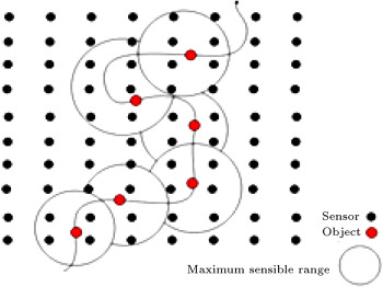
For a physical phenomenon to be observed, it can be modeled either as a field source, as in the monitoring of environment temperature, or as a point source, such as in target detection applications [5] . Suppose, as shown in Figure 1 , that an object that generates data is moving across the network. In this paper, we explore several low overhead methods that use the Rate Distortion (RD) theory for data aggregation of the object via a cluster-based communication model. One technique is the static cluster-based approach. Another approach uses dynamic clustering. Finally we, propose a hybrid method that can take advantage of both static and dynamic methods. The Rate Distortion (RD) theory uses spatial correlation for reducing the network traffic, provided that resultant distortion does not exceed a certain value defined by the user.
|
|
|
Figure 1. Moving of an object in sensor network. |
The rest of this paper is organized as follows. Section 2 discusses the background and related work on data aggregation techniques utilizing correlation. Section 3 describes the aggregation model and derives all the mathematical relationships. In Section 4 , the proposed protocols are disclosed and their operation is elaborated upon. Simulation is disclosed in Section 5 , and finally, the paper is concluded in Section 6 .
2. Related work
Various studies have been done based on using spatial correlation for reducing the network traffic size. In [5] , the authors exploit the spatial correlation on the Medium Access Control (MAC) layer for preventing redundant transmissions from closely located sensor nodes. In [6] and [7] , correlation is used for the purpose of lossy data aggregation in the aggregation points. In other algorithms, such as in [4] , [8] , [9] and [10] , correlations are used for grouping sensor nodes into clusters. Some other works, such as [11] , are based on distributed source coding for data aggregation. The authors in [12] present the YEAST method that maximizes data aggregation along the communication route, based on the notion of a spatial correlated region, and decreases the costs in route discovery. All these methods only consider field source phenomenon, but in the real world, the physical event may be mobile, so the communication protocols should be designed to support mobility in an energy-efficient manner.
Research efforts in [13] , [14] , [15] and [16] address aggregation for mobile object. LPSS [13] experiments with filtering out spatial correlation among the sensing reports of sensor nodes from mobile sources. The authors in [13] first obtain a distance to the event source in which all sensing reports are collected to minimize the reconstruction distortion. Then, in order that the mobility of the event source may be considered, sensor nodes are self-scheduled to join or leave the representative node group, which guarantees that those appropriate nodes would always be a group member. LPSS only emphasizes optimal distance to a mobile source and does not use any specific structure for data aggregation. Also, this method causes a high overhead when sending relay messages when the velocity of the object increases. The protocol in [14] is concentrated on the aggregation for a mobile object. In this study, a cluster of nodes is constructed and updated around the object by moving that object. Aggregation is performed based on a max aggregator. The authors do not use the correlation between data in the aggregation operation. Studies in [15] and [16] also focus on the aggregation for mobile events. In these works, no specific structure is used for aggregation, due to its dynamic nature. They propose two corresponding mechanisms: Data-Aware Anycast at the MAC layer and Randomized Waiting at the application layer. Here, too, no correlation is supposed between the data. In addition, no specific data model is introduced.
3. Aggregation model
3.1. Spatial correlation of point source phenomenon
One application of WSN is in measuring the generated signal from the object [17] . Assume the object generates a contiguous signal that can be described by a Gaussian random process. This random signal can be represented by , where and denote object coordinate at time . Assume is Wide Sense Stationary (WSS), so and . We assume that and the object movement before the signal reaches the sensor nodes is negligible. Received signal by sensor at location is formulated as follows:
|
|
where denotes signal propagation speed, is the attenuation constant and is the white Gaussian noise with zero-mean and variance equal to .
Since the function is a Gaussian random process, the samples taken by the sensors are Jointly Gaussian Random Variables (JGRVs). In order for the mathematical operations to become easier on function , we change the above equation as follows:
|
|
( 1) |
where . The mean of the received signal, , is zero and the variance is formulated as follows:
|
|
Since and are independent, . So, we have:
|
|
( 2) |
Lemma 1.
Spatial correlation between the two sensors, and , at time is obtained from the formula given in Box I.
|
|
where:
|
|
Proof.
Spatial correlation between the two sensors, and , at time is formulated as follows [18] :
|
|
where is used to express the discrete sampling values of at time by sensor . So, from Eq. (1) , we have:
|
|
We also assume that and are independent for [5] . So, we have:
|
|
( 3) |
In (3) , .
So, using Eqs. (2) and (3) , we have the equation given in Box II .
|
|
According to [18] :
|
|
( 4) |
Hence, we have Eq. (5) given in Box III [19] : where is the correlation degree. In Eq. (5) , by ignoring observation noise, . □
|
|
( 5) |
The correlation matrix at time can be obtained using Eq. (5) :
|
|
( 6) |
3.2. The RD theory
Let us suppose that a source point generates a signal, , and that we wish to work out the minimum bits required to quantize it using an encoder, such that the distortion between and its representation, , is less than after decoding at the destination point. The minimum required number of bits to represent , such that , is computed from the following equation [20] :
|
|
( 7) |
where is a bound on distortion, is squared error distortion and is mutual information between and . Eq. (7) is solved only for Gaussian sources. So, for , we have [20] :
|
|
( 8) |
If signal is a vector of independent Gaussian Random variables, each one with , the RD function is computed from the following equation [21] :
|
|
( 9) |
Or is chosen such that [21] :
|
|
( 10) |
where for are equivalent to eigenvalues of the correlation matrix [22] . In other words, only random variables with variance greater than are described and no bits are assigned to other random variables with variance lower than .
3.3. Aggregation using the RD [23]
Suppose that when an object moves through the network, sensors around the object can form a cluster with a CH, selected using a fair mechanism. Cluster members must send their position information, along with object position, to the CH. The CH uses this information to calculate the correlation matrix for the cluster using Eq. (6) . Then, using the matrix, it obtains eigenvectors and eigenvalues and, finally, using known and eigenvalues, computes from Eq. (10) . Suppose the CH receives the signal from cluster members. Now, in order to apply the RD, must be transformed into another vector, , with independent Gaussian elements, using the following expression:
|
|
( 11) |
where is the transposition of the eigenvectors for the correlation matrix. Then, after obtaining , CH substitutes the calculated eigenvalues and in Eq. (9) and calculates the minimum required number of bits to represent with the distortion bound . It is possible at this stage that no bits are allocated to some elements of , since the corresponding eigenvalues for these elements are smaller than the calculated value of . Finally, the CH sends final vector and the object position to the sink node. At the sink node, the reverse of the mentioned operations takes place, which means applying the inverse of Eq. (11) to to construct , the original data with distortion.
By moving the object across the network (see Figure 1 ), the cluster around the object is changed and the correlation matrix must be calculated for these new clusters in the moving path at each sampling time. To avoid these high computation overheads, we introduce, in the next section, a mechanism that uses the pre-calculated matrices using an approximation of object position. We will demonstrate in the simulation section that object position approximation in the aggregation has very little effect on achieved distortion (achieved error).
4. Data aggregation for mobile object using RD with clustering
We will assume that the network includes several grids in all methods described in this section. The centers of these grids are used for approximation of object position to pre-calculate correlation matrices. Our proposed protocols are not restricted to grid-based networks. These protocols only need a virtual division of the network to grids for approximation of object position, to reduce the high overhead of RD-based data aggregation of a moving object. In sub-section A, we introduce the static cluster-based method called DAMORD-SC, then, move on to B, where the dynamic cluster based technique called DAMORD-DC is examined. This is followed by an explanation of the calculation in C. The DAMORD-HC solution is explored in detail in D.
4.1. DAMORD-SC
In DAMORD-SC [17] , the entire network is split into several static clusters, such that several equal size grids are considered in each cluster. Assume the size of clusters is pre-specified. To form static clusters, first, pre-selected CHs broadcast advertisement messages in the network. The maximum broadcast range of advertisement messages is half of a cluster diameter. Each sensor node that receives advertisement messages estimates its distance from the CHs and selects the nearest CH for its CH. Then, the sensor node informs selected CH by sending a join request. Having received join requests from the sensor nodes, the CH sends them the data sending schedule.
In this method, the sink node computes correlation matrices for each cluster before the beginning of data collection, where denotes the number of grids in each cluster. To calculate the matrices, the sink assumes the object is in the center of the grids. Once the matrices are calculated for each cluster, eigenvectors and eigenvalues are sent to CH inside the cluster. In DAMORD-SC, the sensor nodes can detect object position using the strength and direction of the object signal. Also, each node knows its position, its grid range and its cluster range in the network.
Suppose a round is begun every second. This second is fixed and is determined by the sink node. At the beginning of each round, sensor nodes awake simultaneously and sense the environment. If the object is inside a cluster, this round becomes a transmission round for sensor nodes inside that cluster, so, they send their sensed data from the object to the CH, alternately. The last node in the transmission round sends the grid number of the grid, inside which the object is located, in addition to its data. Then, member nodes go to sleep mode and awake at the next round. When the CH node receives all member nodes data, it uses the grid number to recover pre-calculated eigenvectors and eigenvalues for this grid. Then, the CH aggregates member nodes data and sends results, along with grid number, to the sink node. The sink node uses the grid number to obtain original data with distortion. On the other hand, if the sensor nodes find the object is not resident in their cluster after sensing the environment, these nodes go to sleep mode again and awake at the next round.
Suppose CH receives data from all cluster members, if so, it must construct the vector. Next, it receives the grid number, so, it recovers pre-calculated eigenvectors and eigenvalues for this grid. Then, it calculates distortion, , using Relation (22) . Next, having obtained eigenvalues and , it can calculate using Eq. (10) . Then, CH transforms vector to vector using Eq. (11) . Next, it applies RD on using Eq. (9) and constructs the vector. Finally, the CH sends this vector, along with the grid number of the grid, inside which the object is located, to the sink node. The sink node constructs original data with distortion using the inverse of these operations.
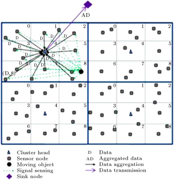
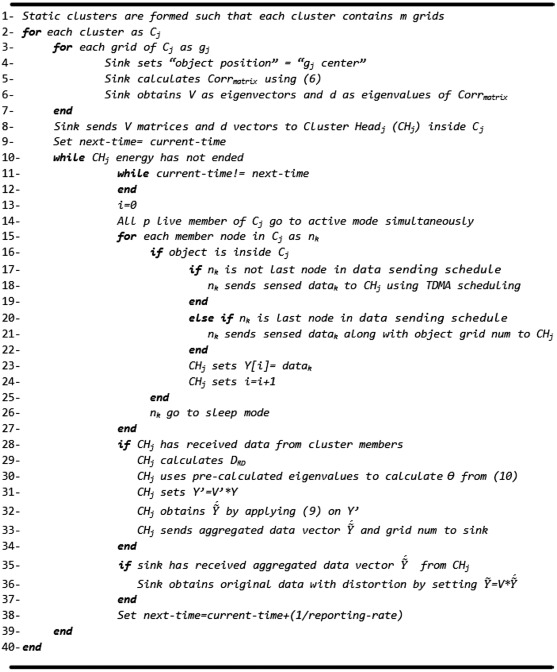
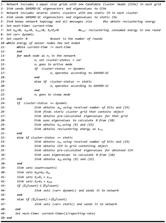
Figure 2 illustrates the operation of data aggregation and data transmission in the DAMORD-SC method. As can be seen, the network has been split into 4 clusters and there are 9 grids in each cluster, all of which are marked with numbers. The object has been detected in grid 8 for one of the clusters. The cluster members send their data to the CH after receiving a signal from the object. Here, one of the nodes (last node in transmission round) sends the object grid number to the CH in addition to its own data. The CH performs aggregation after receiving nodes data and then sends the aggregated data to the sink node. The DAMORD-SC protocol is shown in Figure 3 .
|
|
|
Figure 2. Operation of data aggregation and data transmission using DAMORD-SC. |
|
|
|
Figure 3. DAMORD-SC protocol. |
4.2. DAMORD-DC
In DAMORD-DC, equal size grids are considered in the network and there is a sensor node called Candidate CH (CCH) in each grid. Depending on the object position, the grids can be combined to form a square cluster. In this method, the object is always in the central grid of a cluster, so, the average distance of the cluster nodes to the object is lower than DAMORD-SC. Therefore, data accuracy in DAMORD-DC is higher than in DAMORD-SC.
Suppose the size of clusters is pre-specified and each cluster includes maximum grids ( being odd). The sink node knows the network topology. It considers a cluster for each grid in the network, such that the grid is in the center of the cluster. So, the sink node considers clusters and then calculates the correlation matrix and eigenvectors for each of them before the beginning of data collection in the network. To calculate the correlation matrix for each cluster, the sink node assumes the object is in the center of the cluster. Then, it transmits eigenvectors and eigenvalues of the correlation matrix to the CCH inside the central grid of the cluster. In DAMORD-DC, similar to DAMORD-SC, the sink node sends eigenvectors and eigenvalues, where is the number of grids in the network.
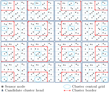
Figure 4 shows different clusters that the sink node considers for the network, including 16 grids. In this figure, is 9 and the sink node must consider 16 clusters. Then, it must calculate 16 correlation matrices and eigenvector matrices. Next, it must transmit each cluster eigenvector to the corresponding CCH in the cluster.
|
|
|
Figure 4. Different dynamic clusters that sink considers. |
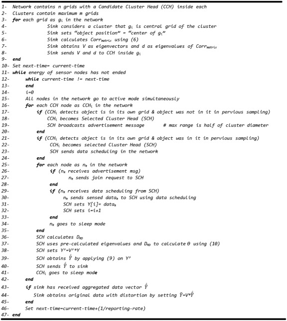
We assume the sensor nodes know their position information. Also, CCHs know their grid position information. Using the received strength and direction of the object signal, sensor nodes can detect the object position in the network. First, sensor nodes are in sleep mode. Second, they awake simultaneously at the beginning of each round. If a CCH node detects the object is inside its own grid, then this node becomes the Selected Cluster Head (SCH) at this time. If the object was not inside this grid at the previous round (SCH keeps only the previous round object position and data sending schedule), the SCH broadcasts the advertisement message in the network. The maximum broadcast range of advertisement messages is the half of a cluster diameter. Sensor nodes that receive an advertisement message send a join request to the SCH. Then, the SCH sends these nodes data the sending schedule. Then, sensor nodes send their sensed data from the object to the SCH, according to this scheduling. If the object was also inside the SCH grid at the previous round, the SCH sends only the data sending schedule. The sensor nodes then go into sleep mode again and awake at the next round. When SCH receives cluster members data, it performs aggregation and sends the resultant data to the sink node.
But, if a CCH node detects that the object is not inside its own grid, after sensing the environment, it goes into sleep mode. Sensor nodes that do not receive any advertisement or data scheduling message also go into sleep mode and awake after seconds. Suppose the SCH receives data from all cluster members, if so, it must constitute . Next, it calculates distortion using Relation (22) . Then, it uses the pre-calculated eigenvalues and to calculate using Eq. (10) . For applying the RD, the SCH transforms vector to vector using Eq. (11) , and, then, as explained earlier, it applies RD to this vector to construct the vector. Next, it sends the aggregated data vector, along with object position, to the sink node. Since the sink node knows the number of cluster members, it puts zero in the place of the removed elements of the received vector. Now, the sink node recovers the pre-calculated correlation matrix and eigenvectors using SCH id and then the original data with distortion can be constructed by applying the inverse of Eq. (11) to these vectors.
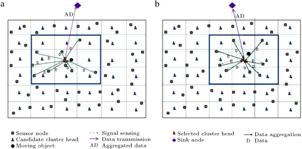
Figure 5 illustrates the operation of data aggregation and data transmission using the DAMORD-DC method. As can be seen, there are 36 grids and CCHs in the network. Also, each cluster is assumed to include 9 grids. Now, looking at Figure 5 (a), we can see that sensor nodes have constructed a cluster around the object. Also, Figure 5 (b) tells us that a new cluster has been constructed around the object when the object has moved to an adjacent grid. From these investigations, it is evident that cluster members, having sampled the object, send their data to the SCH for aggregation and then aggregated data is routed to the sink node. Looking at Figure 2 and Figure 5 , we find that in DAMORD-DC, unlike DAMORD-SC, the object is always inside the central grid of a cluster. So, in DAMORD-DC, the average distance between cluster members and the object is less than DAMORD-SC. The DAMORD-DC protocol is shown in Figure 6 .
|
|
|
Figure 5. Operation of data aggregation and data transmission using DAMORD-DC. |
|
|
|
Figure 6. DAMORD-DC protocol. |
4.3. Calculation of 4.3. Calculation of
D
R
D
{\textstyle D {RD}}
Suppose that the end user defines total distortion, . The aim is to derivate from . is the maximum distortion that RD theory can apply for aggregation. After receiving the aggregated data vector of size in the sink node, we must have:
|
|
( 12) |
where is the recovered sensor data in the sink node and is the source data generated using a moving object. Also, employing the RD, we arrive at:
|
|
( 13) |
where is the sensor data that is received from the object. By solving Eq. (13) , we have:
|
|
( 15) |
By substituting Eqs. and into Relation (12) , we have:
|
|
where is the average value of sensor nodes data in the CH before data aggregation. By substituting in the above expression, we have:
|
|
( 17) |
In Relation (17) , since 0, we have:
|
|
( 18) |
Hence, by looking at Relation (18) , if Relation (19) holds true, then Relation (17) also will hold true. Using Relation (19) , we have:
|
|
( 20) |
If is closer to the upper band of Relation (20) , a lesser number of bits are required to send the aggregated data. So, we use the following relationship to work out :
|
|
( 21) |
Suppose that sensor nodes send their position information to the CH along with their data. By looking at Relation (21) , since the CH does not have the source data ( ), it can estimate using the data of the nearest node to the object. Let us denote this estimated value as and calculate instead of using the following expression:
|
|
( 22) |
We assume there are enough nodes in the network, so, the effect of estimating using (that leads to calculation of instead of ) becomes negligible. This means that is nearly the same as ; as a result, is almost equivalent to . Since, if we have a sufficient number of nodes in the network, the object gets closer to the sensor nodes, therefore, becomes more similar to .
4.4. DAMORD-HC
As mentioned earlier, in DAMORD-DC, unlike DAMORD-SC, the object is always in the central grid of a cluster, so, the average distance between cluster nodes and the object is less than DAMORD-SC. This means higher data accuracy is achieved with this method compared with the DAMORD-SC approach, especially when the observation noise is considered. So, based on the RD theory, fewer bits are required in DAMORD-DC to achieve a certain distortion than DAMORD-SC. That means DAMORD-DC sends fewer aggregated bits than DAMORD-SC. This, therefore, leads to lower transmission consumption. One drawback to the DAMORD-DC method, however, is that this method has a high reclustering overhead, while DAMORD-SC has no reclustering overhead. Reclustering overhead is created by exchanging advertisement messages, join request messages and data sending schedule messages between a SCH and cluster members.
DAMORD-HC is a solution that exploits both these methods in order to achieve less energy consumption at all times. If, after finishing a transmission round, the average energy consumed for reclustering is more than the average amount saved as a result of sending less aggregated bits, DAMORD-HC resorts to DAMORD-SC at the next round, else it utilizes DAMORD-DC.
For DAMORD-HC, similar to DAMORD-SC, there are several static clusters in the network. There is one static CH in each static cluster. A sink node computes correlation matrices for each static cluster before the beginning of data collection, where denotes the number of grids in each cluster. To calculate the matrix for each grid of a cluster, the sink assumes the object is in the center of the grid. Once the matrices are calculated, their eigenvectors and eigenvalues are sent to static CHs, so, each static CH receives eigenvectors matrices and eigenvalues vectors.
Also, in DAMORD-HC, unlike DAMORD-SC but similar to DAMORD-DC, there is a Candidate Cluster Head (CCH) node in each grid. Similar to DAMORD-DC, the sink node considers a cluster for each grid such that the grid is in the center of the cluster. Then, the sink calculates correlation matrices and eigenvectors for the considered clusters. For each cluster, the sink node assumes the object is in the center of the cluster and then transmits eigenvectors and eigenvalues to the CCH inside the central grid of the cluster.
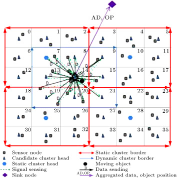
Figure 7 shows there are four static clusters and four static CHs in the network. Also, this figure shows that there are 36 CCHs (static CHs can be CCHs). Both the DAMORD-DC and DAMORD-SC algorithms can be used in DAMORD-HC. If DAMORD-DC is used, static CHs will act as CCHs. If DAMORD-SC is used, CCHs will act as regular sensor nodes.
|
|
|
Figure 7. Structure of network in DAMORD-HC when DAMORD-DC is used by sensor nodes. |
If DAMORD-DC is used by the sensor nodes during the current transmission round, since the sink node knows the network topology and all message sizes, it can calculate the energy consumed for reclustering by the sensor nodes. We call this energy . The sink node considers the advertisement messages, join request messages and data sending schedule messages exchanged between a SCH and cluster members to compute .
The sink node knows a approximation for each grid of a cluster. This node can estimate the difference in the amount of transmission (of the aggregated data) energy between the DAMORD-DC and DAMORD-SC methods during the current transmission round, noting that energy consumption is lower in DAMORD-DC due to higher data accuracy. We call this energy .
DAMORD-HC resorts to DAMORD-SC or DAMORD-DC at the next round, depending on average and average . Assume the sensor nodes use DAMORD-DC at the first round. Now, let us see how all this works: at the end of each round by receiving aggregated data, the sink checks whether DAMORD-DC or DAMORD-SC has been used by the sensor nodes.
If DAMORD-DC has been used at this round, using the number of received bits from a SCH and its distance to the SCH, the sink obtains the aggregated data transmission energy of SCH using Eq. (23) . This energy is called . Then, the sink must obtain the transmission energy of sending aggregated data, making the assumption that there is static and not dynamic clustering. This energy is called . For this purpose, the sink node finds a static cluster grid, shown using , inside which the object is located using reported object position information by the SCH. Also, static CH, in which the static cluster object is located, is called . Next, the sink node recovers pre-calculated eigenvalues for in the cluster to compute using Eq. (10) . This is then followed by calculation of the number of aggregated bits by utilizing Eq. (9) . Finally, by knowing its distance to , the sink computes using Eq. (23) . After computing and , the sink computes . Figure 7 shows the sensor nodes using DAMORD-DC to send their data to CCH inside grid 14. Then, this node sends aggregated data, together with object position information, to the sink node. The sink node, using the number of received bits from the CCH and its distance to the CCH, must calculate from Eq. (23) . Then, the sink node can detect the object is inside the ninth grid of the left-most and highest static cluster using the object position information. In this example, is 9 and is the static cluster inside grid 7. Then, the sink node can compute after recovering pre-calculated eigenvalues for grid 9 of the left-most and highest static cluster. Then, the sink can calculate the number of aggregated bits using Relation (9) . Finally, using the number of aggregated bits and its distance to , it can compute from Eq. (23) . After computing and , the sink node must calculate using Eq. (23) , by considering exchanged messages between cluster members and CCH inside grid 14 to form the dynamic cluster shown in Figure 7 .
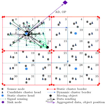
Otherwise, if DAMORD-SC has been used at this round, using the number of received bits from a static CH and its distance to the static CH, the sink obtains the aggregated data transmission energy of static CH using Eq. (23) . This energy is called . Then, the sink must obtain the transmission energy of sending aggregated data, making the assumption that there is dynamic and not static clustering. This energy is called; . For the sink node to work this out, it must obtain a CCH inside the grid in which the object is located and then must use pre-calculated eigenvalues for that CCH to calculate using Eq. (10) . Finally, it uses Eq. (9) to obtain the number of aggregated bits. The sink node then uses Eq. (23) to calculate by knowing its distance to the CCH. Finally, since static cluster has been used at this round, the sink node must set zero in . Figure 8 shows the sensor nodes, located in the left-most and highest static cluster, sending sensed data from the object to a static CH located in grid 7. The static CH then sends aggregated data, together with object position information, to the sink node. The sink node, using the number of received bits from the static CH and its distance to this node, must calculate from Eq. (23) . Then, the sink node must detect that the object is inside grid 14 using received object position information. Then, this node must recover pre-calculated eigenvalues for a CCH located in grid 14 to calculate . Then, the sink can calculate the number of aggregated bits using Relation (9) . Next, is computed from Relation (23) using the number of aggregated bits and the sink distance to the CCH located in grid 14. Finally, the sink node must set zero for , since sensor nodes have used static cluster to send their data.
|
|
|
Figure 8. Structure of network in DAMORD-HC when DAMORD-SC is used by sensor nodes. |
Hence, after finishing each transmission round, the sink node computes , and which, regardless of the dynamic or static nature of the cluster at the current round, allows it to calculate . The sink node obtains by summing all and by summing all after finishing all transmission rounds, respectively. Assume the number of rounds is up to this moment, depending on whether or , the sink broadcasts across the network that during the next transmission round, DAMORD-SC or DAMORD-DC must be used, respectively. Sensor nodes, then, will switch to DAMORD-DC or DAMORD-SC at the next transmission round, according to the sink command. The DAMORD-HC algorithm is shown in Figure 9 .
|
|
|
Figure 9. DAMORD-HC protocol. |
5. Simulation
5.1. Energy evaluation mechanism
To evaluate the effectiveness of the algorithms and the protocols, different aspects of a sensor node must be modeled accurately and energy consumption must be measured for comparison purposes.
5.1.1. Communication energy evaluation
We used both the free space ( power loss) and multi-path fading ( power loss) channel models to evaluate communication energy. In these models, to transmit the bit packet, at distance , consumption energy is computed from the following equation [24] :
|
|
( 23) |
and to receive the bit packet, consumption energy is [24] :
|
|
( 24) |
Where denotes electronics energy and or denote amplifier energy. in Eq. (23) can be obtained by equating the two equations, thus it is equal to .
5.1.2. Computation energy model
We employed a Sim-Panalyser [25] to estimate the computation energy of the proposed protocols. This instrument is a cycle accurate power simulator for the ARM instruction set architecture. Sim-Panalyzer is an extension of sim-outorder that is the most detailed simulator in the Simple Scalar suite [26] . We assumed sensor nodes have a Strong Arm SA-1100 processor and configured the simulator so as to simulate an ARM architecture operating at 200 MHz, 16 KB data cache and 16 KB instruction cache. The power model of the simulator models distinct parts of a processor, e.g. I/O power models, cache power models, clock tree power models, data path and execution unit power models [27] . The simulator takes the computation parts of protocols, written in C, and estimates the overall energy consumed by the desired processor in executing these parts after compiling it for the target architecture [28] .
We simulated the proposed methods using NS-2 [29] . Our simulation scenarios have sets of constant and variable parameters (see Table 1 for constant parameters). Variable parameters will be shown for each experiment separately.
| Parameter | Value | Parameter | Value |
|---|---|---|---|
| Area | [1..240,1..240] m | Eelec | 50 nJ/bit |
| Simulation time | 500 s | Number of grids for each cluster | 9 |
| 10 pJ/bit/ | Node initial energy | 5 j | |
| 0.0013 pJ/bit/ | Reporting-rate | 1 sample/s | |
| Object minimum speed | 0 m/s | 0.0013 [30] | |
| Object pause time | 0.001 s | YEAST communication radius | 70 m |
| 1 |
5.2. Simulation environment
We suppose that cluster size is predefined. We also assume that sensor nodes send their data to the CH in one hop alone, and that, likewise, CHs send their aggregated data to the sink in one hop. It is assumed also that nodes are distributed uniformly in the environment. Since correlation degree ( ) is a variable that depends on environmental conditions, its value is already known. Also, observation noise variance has a known value. It is further assumed that the object generates an audio signal at a propagation speed of 340 m/s [31] .
Let us suppose that the object movement model is a random way point. However, we claim that our proposed schemes can be applied to other mobility models. Let us also suppose that the cluster member data has a Gaussian distribution. We generated artificially Gaussian distributed correlated data at the specified correlation degree sensed from the object. During the simulation run, cluster members send this data to the CHs. To generate the artificial data, first, the network topology information, along with the actual position of the object, is put through the MATLAB. After calculating the network correlation matrix, the covariance matrix needs to be obtained from the following formula:
|
|
( 25) |
Next, vector with independent elements, zero mean Gaussian distribution and variances equal to source signal variance, are calculated. Let us assume the Cholesky decomposition of covariance matrix is , the correlated data vector, , for the sensors is derived from the following equation:
|
|
( 26) |
This artificial data generation procedure is repeated by sampling of an object in the network during simulation.
The proposed algorithms consist of two parts that concern CHs computations. The first part includes an operation, which is performed during the beginning of the network operation for saving received information, such as eigenvalues, and the transpose of eigenvectors in the memory, and the second part includes consumed energy at the end of each round, when the CH has to aggregate gathered data from the cluster members. This part involves calculating from Eq. (10) , multiplying the eigenvector matrix by the correlated data and working out the required number of bits to represent uncorrelated data. For each part, we wrote the C code, applied it to Sim-Panalyzer and obtained energy results that we used during the simulation.
We will compare our proposed methods against LPSS and YEAST, since Lpss is the most similar work to our methods and YEAST is the most recent work that uses spatial correlation for aggregation. In the simulation scenarios, to calculate the required number of bits for the sensor nodes, without RD, Lpss and YEAST methods, we use the following equation:
|
|
( 27) |
where is equal to and is the number of nodes that send their data. Since, in these methods, the required number of bits that are assigned has to be such that there is zero correlation between sensor nodes, all eigenvalues of data sender nodes are equal to 1 and . Thus, Eq. (27) can be derived from Eq. (9) .
To study the effectiveness of RD in the data aggregation of moving objects, we choose DAMORD-SC randomly from our proposed methods, in this paper, and compare it with the without RD method in the simulation section. In the without RD method, clusters are formed according to DAMORD-SC, but when CHs receive cluster members data, it is sent directly to the sink node without any aggregation.
In order to ensure that energy results do not depend on the duration of simulation, we extract the results per transmission round.
5.3. Simulation results
In all figures of this section, hybrid refers to DAMORD-HC, dynamic refers to DAMORD-DC, and static refers to DAMORD-SC.
5.3.1. Impact of correlation degree
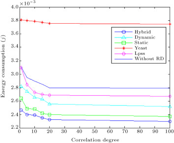
Figure 10 displays energy results per transmission round versus different correlation degrees, constant desired distortion at , constant variance of observation noise equal to 0.01, sink node position of (120 m, 240 m), grid edge size of 24 m, object maximum speed of 12 m/s and number of nodes equal to 240. As can be seen, in all cases, increase in correlation degree results in reduction of energy consumption. Since, by increasing the correlation degree, the data is more correlated, less amounts of data are sent to the sink, thus, energy is conserved. For the YEAST, Lpss and without RD methods, the required number of bits for sending to the sink is obtained using Eq. (27) . By increasing correlation degree, and begin to converge and from Relation (22) , becomes greater, which means that less numbers of bits are sent to the sink node, so, energy consumption decreases.
|
|
|
Figure 10. Energy consumption for different . |
Figure 10 shows the hybrid method outperforms the dynamic and static methods, since, as was discussed earlier, it takes advantage of these two techniques. Also, this figure shows that the hybrid solution consumes, on average, 13% less energy than the Lpss method for different correlation degrees, since, in Lpss, unlike our proposed methods, the number of bits for data sender nodes are assigned by ignoring correlation and also that Lpss has the high overhead of broadcasting relay messages. The hybrid method also is, on average, 36% more efficient than YEAST, since YEAST has been developed for field sources and is not a low overhead mechanism for data aggregation of moving objects. In YEAST, constructing routing trees to coordinators has a high overhead by the sample moving object.
This figure also shows that the without RD case, which uses static clustering, consumes more energy than the static method. This expresses the effectiveness of RD in data aggregation of moving objects, since reduction of communication energy occurred by the static method is more than the computation energy of this method.
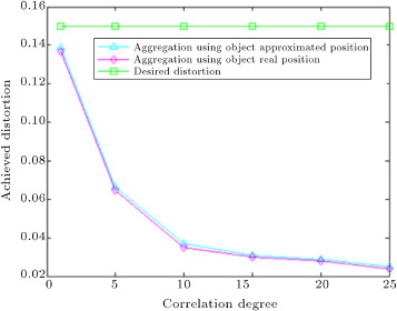
In Figure 11 , the average achieved distortion for different correlation degree, with simulation parameters mentioned for Figure 10 is plotted. We set the simulation to check if the RD resultant achieved distortion is affected by using approximations for object position in our proposed aggregation algorithms. Figure 11 shows the distortion results of our proposed dynamic method which underwent the following tests: First, we performed the RD aggregation based on the real position of the moving object. To do this, when CH was aggregating member nodes data, we loaded it with eigenvectors constructed using the real position of the object. Second, we performed aggregation using the dynamic method, which uses object position approximation for aggregation. Figure 11 illustrates that for different correlation degree, the distortion caused by our method is less than the desired distortion ( ), and that, by increasing correlation degree, achieved distortion falls. It is also evident that the difference between average distortion achieved by performing aggregation based on the real position of an object and average distortion obtained by performing the dynamic method is less than 2%. Similar results were obtained for our other proposed methods.
|
|
|
Figure 11. Average achieved distortion for different correlation degree. |
5.3.2. Impact of desired distortion
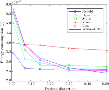
Figure 12 displays consumed energy per transmission round versus different desired distortion, , constant correlation degree of 5, constant variance of observation noise equal to 0.01, sink node position of (120 m, 240 m), grid edge size of 24 m, object maximum speed of 12 m/s and the number of nodes equal to 240. As can be seen, increase in causes energy consumption for all cases to decrease. It can be said that by increasing , end-users can tolerate more distortion, thus, aggregated bit load routed to the sink node is lower. As long as does not exceed 0.23, the hybrid method works better than the other methods and consumes less energy. However, if exceeds this value, LPSS and without RD consume less energy than the hybrid method. Since, for large , the bit load becomes very low for all cases, the energy that is saved, due to the decrease in aggregated bits, in our proposed methods, cannot overcome the computation overhead of these methods. In the Lpss, unlike without RD, due to the overhead of relay messages, energy consumption remains constant after a distortion point of 0.3. For different , the hybrid method works, on average, 35% better than YEAST.
|
|
|
Figure 12. Energy consumption for different desired distortion. |
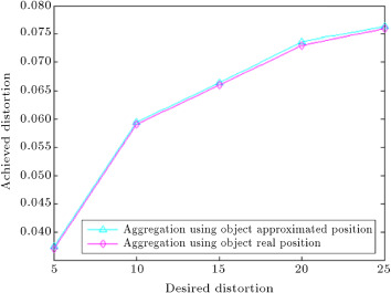
In Figure 13 , average achieved distortion versus desired distortion ( ) with simulation parameters mentioned for Figure 12 is shown, where it is seen that, as changes, achieved distortion falls below . The simulation steps are as follows: Initially, we performed RD aggregation based on the real position of the moving object, then, we repeated the aggregation using the dynamic method that uses an approximation of the object location. Figure 13 illustrates that the difference between average achieved distortions for these two aggregation scenarios is less than 2%. For our other methods, similar results were obtained.
|
|
|
Figure 13. Average achieved distortion for different desired distortion. |
5.3.3. Impact of sink position
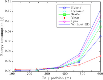
Next, we changed sink node position and ran simulations. The result of energy consumption per transmission round is shown in Figure 14 . In this case, a correlation degree of 5, desired distortion of 0.15, variance of observation noise equal to 0.01, sink node coordinate of 120 m, grid edge size of 24 m, object maximum speed at 12 m/s and 240 sensor nodes were used. As can be seen, when the sink node has moved farther away from the network, all methods consume higher energy. Turning to Figure 14 , it is clear that when the sink node moves to (120, 600), the hybrid method works 36% more efficiently than Lpss. Since correlation is ignored to assign the number of bits for data sender nodes in Lpss, in this method, the network traffic load to the sink node is higher than the hybrid method. So, more energy than the hybrid method is consumed in Lpss when the sink goes farther from the network. Another point that can be made about this result is that, as long as sink y position does not exceed 360 meters, the hybrid method works, on average, 33% better than YEAST, but, after this location, YEAST works better, since sending coordinators data to the sink is a trivial part of energy consumption in YEAST. In this method, construction of routing trees to coordinator nodes consumes much energy that is not affected by the sink movement.
|
|
|
Figure 14. Energy consumption for variable sink position. |
Figure 14 also shows that the without RD case consumes more energy than the static method. This expresses the effectiveness of RD in data aggregation of a moving object, since data aggregation using RD decreases communication energy, such that the computation energy of the aggregation algorithm in the static method becomes insignificant.
5.3.4. Impact of noise variance
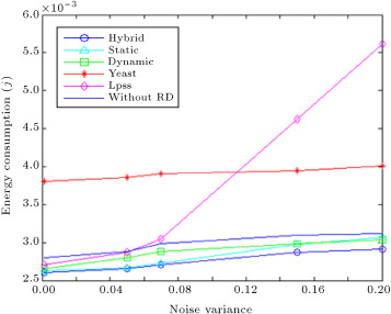
Figure 15 sketches consumed energy per transmission round versus different observation noise variance, constant desired distortion of , sink node position of (120 m, 240 m), correlation degree of 5, grid edge size of 24 m, object maximum speed of 12 m/s and the number of nodes equal to 240. As can be seen, the hybrid method beats all other methods and consumes less energy for different levels of noise variance. When the noise variance is 0.2, this method works 49% better than Lpss. Since, by increasing noise variance, the optimal distance to the object increases quickly, by increasing optimal distance, more sensor nodes send their data to the sink node. Also, sending relay messages causes more energy, while for the hybrid method, by increasing noise variance, the number of sending bits to the sink only slightly increases. Also, from this figure, the hybrid method works, on average, 36% better than YEAST.
|
|
|
Figure 15. Energy consumption for variable noise variance. |
As long as the noise variance is low, energy consumption in the static method is less than the dynamic method. However, the trend in consumption reverses once the noise variance passes a certain point. In the dynamic method, the average distance of cluster members to the object is less than that in their static counterpart, so, noise impacts the latter method more than the former. By increasing noise variance in the environment, the increase in for the static method becomes more than for the dynamic method. Therefore, using Relation (22) , an increase in noise variance causes a drop in ,which is steeper in the static method than in the dynamic method. Finally, more transmit bits are routed from the CHs to the sink node by decreasing . If the noise variance exceeds 0.15, the increase in energy consumption for the static method, due to an increase in the number of bits sent, overcomes the energy consumed due to reclustering in the dynamic method, so, the energy consumed by the static method exceeds that of its rival method.
5.3.5. Impact of object speed
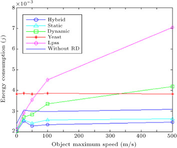
Figure 16 depicts consumed energy per transmission round versus different maximum object speed, constant desired distortion of , sink node position of (120 m, 240 m), correlation degree of 5, grid edge size of 24 m, noise variance of 0.01 and the number of nodes equal to 240. This scenario is based on object maximum speed in the environment, since the object movement model is a random way point, and speed is selected randomly between 0 and a maximum value. As can be seen, an increase in the object maximum speed raises energy consumption in Lpss, since, by increasing object speed, the rate of sending relay messages must increase quickly to avoid losing the object. While, by increasing object speed the hybrid method switches to the static method, energy consumption remains constant for this method. This figure shows that when the object maximum speed is 500, the hybrid method consumes 65% less energy than Lpss and 36% less energy than the YEAST method. The YEAST method constructs aggregation trees at all sampling times, so different speeds do not affect this method.
|
|
|
Figure 16. Energy consumption for different object speed. |
5.3.6. Impact of grid size
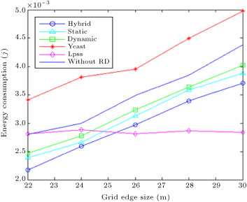
Figure 17 exhibits consumed energy per transmission round versus different grid edge size at constant desired distortion , sink node position of (120 m, 240 m), correlation degree equal to 5, object maximum speed of 12 m/s, variance of observation noise of 0.01 and the number of nodes equal to 240. Each cluster contains 9 grids, so the cluster size is changed by changing grid size.
|
|
|
Figure 17. Energy consumption for different grid edge size. |
As can be seen by increasing grid edge size, energy consumption rises in all of our proposed methods, since, by increasing grid size, cluster size will also increase. By increasing cluster size, reclustering will have more overhead in the dynamic method. Also, by increasing cluster size, the average traffic load of CHs to the sink will increase in the static method (due to an increase in the average distance of cluster members to the object). Since the hybrid method uses both methods, energy consumption will increase in this method by increasing cluster size.
Grid size has no bearing on Lpss and YEAST, so, we assumed that the event sensible region size is equal to cluster size, and changed the event sensible region for these methods. Since the optimal distance to the mobile source is not changed for the LPSS, by increasing the event sensible region, energy consumption remains constant for this method, while energy consumption increases in the hybrid method by increasing cluster size. So, when the grid edge size exceeds 25 m, LPSS works better than the hybrid method. From this figure, by increasing the object sensible range, YEAST consumes more energy, since the construction of aggregation trees will have more overhead by increasing the object sensible range. This figure shows when grid size is 30 m (the object range is 45 m), the hybrid method works 30% better than YEAST.
5.3.7. Impact of network scale
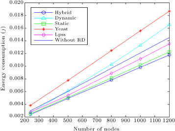
Figure 18 exhibits consumed energy per transmission round versus different number of nodes, constant desired distortion , sink node position of (120 m, 240 m), correlation degree equal to 5, object maximum speed of 12 m/s, variance of observation noise of 0.01 and grid edge size of 24 m. This figure shows that by increasing the number of nodes in the network, the increase in energy consumption for Lpss is more than for the hybrid method. By increasing the number of nodes, reclustering causes more energy, so, the hybrid method switches to the static method most times. Although, by increasing the number of nodes, the data traffic of sensor nodes to CHs increases in the hybrid method, sending relay messages, in addition to data traffic, in Lpss causes more energy consumption than the hybrid method. Also, this figure shows that by increasing the sensor nodes, the hybrid method works better than YEAST, due to the high overhead of creating aggregation structures in YEAST by the moving object.
|
|
|
Figure 18. Energy consumption for different number of nodes. |
When the number of nodes is 1200, the hybrid method consumes 36% less energy than YEAST and 13% less energy than Lpss.
6. Conclusion
The aim of this paper is to present an energy efficient method for data aggregation of a moving object via a cluster based communication model. In the literature, data aggregation algorithms have not taken into account all aspects of aggregation of the moving object data. In this work, we began by introducing a model for aggregation of point sources, using the RD, and then introduced three different protocols to help with this model. We verified that the protocol that uses static clustering has a low clustering overhead, but offers low data accuracy. The protocol that employs dynamic clustering provides high data accuracy but also suffers from high reclustering overhead. We then demonstrated that a hybrid clustering protocol can take advantage of the other two to good effect.
To evaluate the integrity of the proposed solutions, we set up and ran thorough simulation tests and, then, scrutinized the results. Results showed that by using the hybrid method, it is possible to save more than 36% energy when compared to other approaches in the literature. The investigation also confirmed that applying object position approximation in the aggregation protocols leads to less than 2% more achieved distortion.
In this work, we assumed that cluster size is predefined. As future work, we intend to find the optimum size for clusters in our proposed methods, such that achieved distortion is less than user defined distortion, and minimum energy is consumed.
Acknowledgments
This work is partially supported by Iran Telecommunication Research Center (ITRC) , which is greatly appreciated.
References
- [1] J. Lin, N. Xiong, A.V. Vasilakos, G. Chen, W. Guo; Evolutionary game-based data aggregation model for wireless sensor networks; Int. J. Commun., 5 (3) (2011), pp. 1691–1697
- [2] F. Yao, A.L.P. Chen; Energy efficient schemes for accuracy-guaranteed sensor data aggregation using scalable counting; IEEE Trans. Knowl. Data Eng., 24 (8) (2012), pp. 1463–1477
- [3] E. Fasolo, M. Rossi, J. Widmer, M. Zorzi; In-network aggregation techniques for wireless sensor networks: a survey; Int. J. Wirel. Commun., 14 (2) (2007), pp. 70–87
- [4] M. Yajie, G. Yike, T. Xiangchuan, M. Ghanem; Distributed clustering-based aggregation algorithm for spatial correlated sensor networks; Int. J. Sensors, 11 (3) (2011), pp. 641–648
- [5] M.C. Vuran, I.F. Akyildiz; Spatial correlation-based collaborative medium access control in wireless sensor networks; IEEE/ACM Trans. Netw., 14 (2) (2006), pp. 316- 329–316- 329
- [6] Bai, F. and Jamalipour, A. “3D-DCT data aggregation technique for regularly deployed wireless sensor networks”, 8th Int. Conf. on Communications, pp. 2102–2106 (2008).
- [7] Pourpeighambar, S.B., Aminian, M. and Sabaei, M. “A new method for data aggregation using spatial correlation in WSN”, Int. Symp. on Computer Networks and Distributed Systems, pp. 176–181 (2011).
- [8] SunHee, Y. and Shahabi, C. “Exploiting spatial correlation towards an energy efficient clustered aggregation technique (CAG) [wireless sensor network applications]”, Int. Conf. on Communications, pp. 3307–3313 (2005).
- [9] Chongqing, Z., Binguo, W., Sheng, F. and Jiye, Z. “Spatial data correlation based clustering algorithms for wireless sensor networks”, 8th Int. Conf. on Innovative Computing Information and Control, p. 593 (2008).
- [10] Zhikui, C., Song, Y., Liang, L. and Zhijiang, X. “A clustering approximation mechanism based on data spatial correlation in wireless sensor networks”, Int. Symp. on Wireless Telecommunications, pp. 1–7 (2010).
- [11] Z. Jun, W. Pu, L. Cheng; Distributed data aggregation using Slepian–Wolf coding in cluster-based wireless sensor networks; IEEE Trans. Veh. Technol., 59 (5) (2010), pp. 2564–2574
- [12] L. Villas, A. Boukerche, H. Oliveira, R. Araujo, A. Loureiro; A spatial correlation aware algorithm to perform efficient data collection in wireless sensor networks; Int. J. of Ad Hoc Networks (2011)
- [13] C. Zhi, Z. Ming, G. Ying, D. Xiao; Optimizing energy-efficient reconstruction of mobile point source in sensor networks; Int. J. of Distributed Sensor Networks, 5 (6) (2009), pp. 645–659
- [14] Bouhafs, F., Merabti, M. and Mokhtar, H. “Mobile event monitoring protocol for wireless sensor networks”, Int. Conf. on Advanced Information Networking and Applications, pp. 864-869 (2007).
- [15] Fan, K., Liu, S. and Sinha, P. “On the potential of structure-free data aggregation in sensor networks”, Int. Conf on Computer Communications, pp. 1–12 (2006).
- [16] K. Fan, S. Liu, P. Sinha; Structure-free data aggregation in sensor networks; IEEE Trans. On Mobile Computing, 6 (8) (2007), pp. 929–942
- [17] Pourpeighambar, S.B., Aminian, M. and Sabaei, M. “Energy efficient data aggregation of moving object in wireless sensor networks”, Int. Conf. on ATNAC, pp. 1–8 (2011).
- [18] Vuran, M.C. and Akan, O.B. “Spatio-temporal characteristics of point and field sources in wireless sensor networks”, 6th Int. conf. on Communications, pp. 234–239 (2006).
- [19] Pourpeighambar, S.B. and Sabaei, M. “Cluster based data aggregation of moving object in wireless sensor networks”, Technical Report TR-F12 (2012).
- [20] M. Cover, J. Thomas; Elements of Information Theory; (second edn.)John Wiley (1991) pp. 310–312
- [21] Lotfinezhad, M. and Liang, B. “Effect of partially correlated data on clustering in wireless sensor networks”, Int. Conf. on Sensor and Ad Hoc Communications and Networks, pp. 172–181 (2004).
- [22] Kafedziski, V. “Rate distortion of stationary and nonstationary vector gauaaian sources”, 13th Work. on Statistical Signal Processing, pp. 1054–1059 (2005).
- [23] Aminian, M., Akbari, M.K. and Sabaei, M. “DAMORD: Data Aggregation for Mobile Object using Rate-Disrtion theory”, Technical Report TR-F11, Int. J. of Computer Networks (2012) (submitted for publication).
- [24] Kim, K. “A clustering algorithm based on geographical sensor position in wireless sensor network”, Int. Conf. on Innovative Algorithms and Techniques in Automation, Industrial Electronics and Telecommunications, pp. 245–249 (2007).
- [25] Sim-Panalyzer, [Online]. Available: http://www.eecs.umich.edu/~panalyzer/ .
- [26] T. Austin, E. Larson, D. Ernst; SimpleScalar: an infrastructure for computer system modeling; Int. J. Comput., 35 (2) (2002), pp. 59–67
- [27] S. Chouhan, R. Bose, M. Balakrishnan; A framework for energy-consumption-based design space exploration for wireless sensor nodes; IEEE Trans. on Computer-Aided Design of Integrated Circuits and Systems, 28 (7) (2008), pp. 1017–1024
- [28] S. Chouhan, R. Bose, M. Balakrishnan; Integrated energy analysis of error correcting codes and modulation for energy efficient wireless sensor nodes; IEEE Trans. Wirel. Commun., 8 (10) (2009), pp. 5348–5355
- [29] UCB, LBNL. VINT network simulator,http://www.mash.cs.berkeley.edu/ns/ .
- [30] A. Moorer; About this reverberation business; Int. J. Comput. Music, 3 (1979), pp. 13–18
- [31] Young, K., Mechitov, K., Sundresh, S., Wooyoung, K. and Agha, G. “Resilient localization for sensor networks in outdoor environments”, 25th Int. Conf. on Distributed Computing Systems, 2005, pp. 643–652.
Document information
Published on 06/10/16
Licence: Other
Share this document
Keywords
claim authorship
Are you one of the authors of this document?
