m (Move page script moved page Draft Samper 624436055 to Onate et al 2012a) |
|||
| (8 intermediate revisions by 2 users not shown) | |||
| Line 1: | Line 1: | ||
| − | + | Published in ''Comput. Methods Appl. Mech. Engrg''. Vol. 213–216, pp. 362–382, 2012<br /> | |
| − | + | doi: 10.1016/j.cma.2011.11.023 | |
| − | + | ||
| − | ''' | + | |
| − | + | ||
| − | + | ||
| − | + | ||
| − | + | ||
| − | + | ||
| − | + | ||
| − | + | ||
| − | + | ||
| − | + | ||
| − | + | ||
| − | + | ||
| − | + | ||
==Abstract== | ==Abstract== | ||
| Line 20: | Line 6: | ||
In this work we present a new simple linear two-noded beam element adequate for the analysis of composite laminated and sandwich beams based on the combination of classical Timoshenko beam theory and the refined zigzag kinematics proposed by Tessler ''et al.'' <span id='citeF-22'></span>[[#cite-22|[22]]]. The element has just four kinematic variables per node. Shear locking is eliminated by reduced integration. The accuracy of the new beam element is tested in a number of applications to the analysis of composite laminated beams with simple supported and clamped ends under point loads and uniformly distributed loads. An example showing the capability of the new element for accurately reproducing delamination effects is also presented. | In this work we present a new simple linear two-noded beam element adequate for the analysis of composite laminated and sandwich beams based on the combination of classical Timoshenko beam theory and the refined zigzag kinematics proposed by Tessler ''et al.'' <span id='citeF-22'></span>[[#cite-22|[22]]]. The element has just four kinematic variables per node. Shear locking is eliminated by reduced integration. The accuracy of the new beam element is tested in a number of applications to the analysis of composite laminated beams with simple supported and clamped ends under point loads and uniformly distributed loads. An example showing the capability of the new element for accurately reproducing delamination effects is also presented. | ||
| − | ''' | + | '''Keywords''': Two-noded beam element, zigzag kinematics, Timoshenko theory, composite, sandwich beams |
| + | |||
==1 INTRODUCTION== | ==1 INTRODUCTION== | ||
| Line 28: | Line 15: | ||
Indeed to achieve accurate computational results, 3D finite element analyses are often preferred over beam models. For composite laminates with hundred of layers, however, 3D modelling becomes prohibitely expensive, specially for non linear and progressive failure analyses. | Indeed to achieve accurate computational results, 3D finite element analyses are often preferred over beam models. For composite laminates with hundred of layers, however, 3D modelling becomes prohibitely expensive, specially for non linear and progressive failure analyses. | ||
| − | Improvements to the classical beam theories have been obtained by the so called equivalent single layer (ESL) theories that assume a priori the behaviour of the displacement and/or the stress through the laminate thickness [3,4]. Despite of being computational efficient, ESL theories often produce innacurate distributions for the stresses and strains (in particular the transverse shear stress) across the thickness. | + | Improvements to the classical beam theories have been obtained by the so called equivalent single layer (ESL) theories that assume a priori the behaviour of the displacement and/or the stress through the laminate thickness <span id='citeF-3'></span>[[#cite-3|[3,4]]]. Despite of being computational efficient, ESL theories often produce innacurate distributions for the stresses and strains (in particular the transverse shear stress) across the thickness. |
| − | The need for composite laminated beam theories with better predictive capabilities has led to the development of the so-called ''higher order'' theories. In these theories higher-order kinematic terms with respect to the beam depth are added to the expression for the axial displacement and, in some cases, to the expressions for the deflection. A review of these theories can be found in [3,4]. | + | The need for composite laminated beam theories with better predictive capabilities has led to the development of the so-called ''higher order'' theories. In these theories higher-order kinematic terms with respect to the beam depth are added to the expression for the axial displacement and, in some cases, to the expressions for the deflection. A review of these theories can be found in <span id='citeF-3'></span>[[#cite-3|[3,4]]]. |
Accurate predictions of the correct shear and axial stresses for thick and highly heterogenous composite laminated and sandwich beams can be obtained by using ''layer-wise'' theory. In this theory the thickness coordinate is split into a number of ''analysis layers'' that may or not coincide with the number of laminate plies. The kinematics are independently described within each layer and certain physical continuity requirements are enforced <span id='citeF-3'></span><span id='citeF-4'></span>[[#cite-3|[3,4]]]. | Accurate predictions of the correct shear and axial stresses for thick and highly heterogenous composite laminated and sandwich beams can be obtained by using ''layer-wise'' theory. In this theory the thickness coordinate is split into a number of ''analysis layers'' that may or not coincide with the number of laminate plies. The kinematics are independently described within each layer and certain physical continuity requirements are enforced <span id='citeF-3'></span><span id='citeF-4'></span>[[#cite-3|[3,4]]]. | ||
| Line 36: | Line 23: | ||
A drawback of layer-wise theory is that the number of kinematic variables depends on the number of analysis layers. The layer displacements can be condensed at each section in terms of the axial displacement for the top layer during the equation solution process <span id='citeF-5'></span><span id='citeF-6'></span>[[#cite-5|[5,6]]]. The displacement condensation processes can be however expensive for problems involving many analysis layers. | A drawback of layer-wise theory is that the number of kinematic variables depends on the number of analysis layers. The layer displacements can be condensed at each section in terms of the axial displacement for the top layer during the equation solution process <span id='citeF-5'></span><span id='citeF-6'></span>[[#cite-5|[5,6]]]. The displacement condensation processes can be however expensive for problems involving many analysis layers. | ||
| − | Discrete layer theories in which the number of unknowns in the model does not depend on the number of layers in the laminate are described in [7,8,9]. In this class of discrete layerwise theories (called zigzag theories) a piewise linear in-plane displacement function (the zigzag function) is superimposed over a linear displacement field [7,8], a quadratic displacement field [10,11] or a cubic displacement field [12,13,14] through the thickness of the laminate. | + | Discrete layer theories in which the number of unknowns in the model does not depend on the number of layers in the laminate are described in <span id='citeF-7'></span>[[#cite-7|[7,8,9]]]. In this class of discrete layerwise theories (called zigzag theories) a piewise linear in-plane displacement function (the zigzag function) is superimposed over a linear displacement field <span id='citeF-7'></span>[[#cite-7|[7,8]]], a quadratic displacement field <span id='citeF-10'></span>[[#cite-7|[10,11]]] or a cubic displacement field <span id='citeF-12'></span>[[#cite-12|[12,13,14]]] through the thickness of the laminate. |
Many zigzag theories require <math display="inline">C^1</math> continuity for the deflection field, which is a drawback versus simpler <math display="inline">C^\circ </math> continuous FEM approximations. Also many zigzag theories run into theoretical difficulties to satisfy equilibrium of forces at a clamped support. | Many zigzag theories require <math display="inline">C^1</math> continuity for the deflection field, which is a drawback versus simpler <math display="inline">C^\circ </math> continuous FEM approximations. Also many zigzag theories run into theoretical difficulties to satisfy equilibrium of forces at a clamped support. | ||
| Line 44: | Line 31: | ||
A 2-noded beam element based on Euler-Bernouilli beam theory and an extension of Averill's zigzag theory including a cubic in-plane displacement field within each layer has been recently proposed by Alam and Upadhyay <span id='citeF-18'></span>[[#cite-18|[18]]]. Good results are reported for cantilever and clamped composite and sandwich beams. | A 2-noded beam element based on Euler-Bernouilli beam theory and an extension of Averill's zigzag theory including a cubic in-plane displacement field within each layer has been recently proposed by Alam and Upadhyay <span id='citeF-18'></span>[[#cite-18|[18]]]. Good results are reported for cantilever and clamped composite and sandwich beams. | ||
| − | An assessment of different zigzag theories for beam is reported in <span id='citeF-19'></span><span id='citeF-20'></span>[[#cite-19|[19,20]]]. A review of zigzag theory for plate analysis can be found in [21]. | + | An assessment of different zigzag theories for beam is reported in <span id='citeF-19'></span><span id='citeF-20'></span>[[#cite-19|[19,20]]]. A review of zigzag theory for plate analysis can be found in <span id='citeF-21'></span>[[#cite-21|[21]]]. |
| − | Tessler ''et al.'' [22,23] have developed a refined zigzag (RZ) theory starting from the standard Timoshenko kinematic assumptions. This allows one using <math display="inline">C^\circ </math> continuous interpolation for all the kinematic variables. Timoshenko beam theory also introduces naturally shear deformation effect for the homogeneous material case, which is advantageous for many problems. The zigzag functions chosen have the property of vanishing on the top and bottom surfaces of a laminate. A particular feature of this zigzag theory is that the transverse shear stresses are not required to be continuous at the layer interfaces. This results in simple piewice-constant functions that approximate the true shear stress distribution. An accurate continuous thickness distribution of the transverse shear stress can be obtained “a posteriori” in terms of the axial stress by integrating the equilibrium equations. This theory also provides good results for clamped supports. | + | Tessler ''et al.'' <span id='citeF-22'></span>[[#cite-22|[22,23]]] have developed a refined zigzag (RZ) theory starting from the standard Timoshenko kinematic assumptions. This allows one using <math display="inline">C^\circ </math> continuous interpolation for all the kinematic variables. Timoshenko beam theory also introduces naturally shear deformation effect for the homogeneous material case, which is advantageous for many problems. The zigzag functions chosen have the property of vanishing on the top and bottom surfaces of a laminate. A particular feature of this zigzag theory is that the transverse shear stresses are not required to be continuous at the layer interfaces. This results in simple piewice-constant functions that approximate the true shear stress distribution. An accurate continuous thickness distribution of the transverse shear stress can be obtained “a posteriori” in terms of the axial stress by integrating the equilibrium equations. This theory also provides good results for clamped supports. |
Gherlone et al. <span id='citeF-24'></span>[[#cite-24|[24]]] have developed two and three-noded <math display="inline">C^\circ </math> beam elements based on the RZ theory for analysis of multilayered composite and sandwich beams. Locking-free elements are obtained by using ''anisoparametric'' interpolations that are adapted to approximate the four independent kinematic variables that model the beam deformation. A family of beam elements is achieved by imposing different constraints on the original displacement approximation. The constraint conditions requiring a constant variation of the transverse shear force provide an accurate 2-noded beam element <span id='citeF-24'></span>[[#cite-24|[24]]]. | Gherlone et al. <span id='citeF-24'></span>[[#cite-24|[24]]] have developed two and three-noded <math display="inline">C^\circ </math> beam elements based on the RZ theory for analysis of multilayered composite and sandwich beams. Locking-free elements are obtained by using ''anisoparametric'' interpolations that are adapted to approximate the four independent kinematic variables that model the beam deformation. A family of beam elements is achieved by imposing different constraints on the original displacement approximation. The constraint conditions requiring a constant variation of the transverse shear force provide an accurate 2-noded beam element <span id='citeF-24'></span>[[#cite-24|[24]]]. | ||
| Line 591: | Line 578: | ||
{| class="floating_imageSCP" style="text-align: center; border: 1px solid #BBB; margin: 1em auto; width: 100%;max-width: 100%;" | {| class="floating_imageSCP" style="text-align: center; border: 1px solid #BBB; margin: 1em auto; width: 100%;max-width: 100%;" | ||
|- | |- | ||
| − | |[[Image:Draft_Samper_624436055-test- | + | |[[Image:Draft_Samper_624436055-test-Fig3.png|400px|]] |
|- style="text-align: center; font-size: 75%;" | |- style="text-align: center; font-size: 75%;" | ||
| colspan="1" | '''Figure 2:''' Cantilever beam under point load | | colspan="1" | '''Figure 2:''' Cantilever beam under point load | ||
| Line 599: | Line 586: | ||
{| class="floating_imageSCP" style="text-align: center; border: 1px solid #BBB; margin: 1em auto; width: 100%;max-width: 100%;" | {| class="floating_imageSCP" style="text-align: center; border: 1px solid #BBB; margin: 1em auto; width: 100%;max-width: 100%;" | ||
|- | |- | ||
| − | |[[ | + | |[[File:Draft_Samper_624436055_3572_Fig3-con299.png|600px|]] |
|- style="text-align: center; font-size: 75%;" | |- style="text-align: center; font-size: 75%;" | ||
| colspan="1" | '''Figure 3:''' Mesh of 27000 4-noded plane stress rectangular elements for analysis of cantilever and simple supported beams | | colspan="1" | '''Figure 3:''' Mesh of 27000 4-noded plane stress rectangular elements for analysis of cantilever and simple supported beams | ||
| Line 640: | Line 627: | ||
Figure [[#img-4|4]] shows the ratio <math display="inline">r</math> between the end node deflection obtained with the LRZ element (<math display="inline">w_{zz}</math>) and with the plane stress quadrilateral (<math display="inline">w_{ps}</math>) (i.e. <math display="inline">r=\frac{w_{zz}}{w_{ps}}</math>) versus the beam span-to-thickness ratio <math display="inline">d = \frac{L}{h}</math>. Results for the LRZ element have been obtained using ''exact'' two-point integration for all terms of matrix <math display="inline">{\boldsymbol K}^e_t</math> (Eq.(27)) and a one-point ''reduced'' integration for the following three groups of matrices: <math display="inline">{\boldsymbol K}^e_s</math>; <math display="inline">{\boldsymbol K}^e_s</math> and <math display="inline">{\boldsymbol K}^e_{s\psi }</math>; and <math display="inline">{\boldsymbol K}_s</math>, <math display="inline">{\boldsymbol K}^e_{s\psi }</math> and <math display="inline">{\boldsymbol K}^e_{\psi }</math> (Eqs.(29b)). | Figure [[#img-4|4]] shows the ratio <math display="inline">r</math> between the end node deflection obtained with the LRZ element (<math display="inline">w_{zz}</math>) and with the plane stress quadrilateral (<math display="inline">w_{ps}</math>) (i.e. <math display="inline">r=\frac{w_{zz}}{w_{ps}}</math>) versus the beam span-to-thickness ratio <math display="inline">d = \frac{L}{h}</math>. Results for the LRZ element have been obtained using ''exact'' two-point integration for all terms of matrix <math display="inline">{\boldsymbol K}^e_t</math> (Eq.(27)) and a one-point ''reduced'' integration for the following three groups of matrices: <math display="inline">{\boldsymbol K}^e_s</math>; <math display="inline">{\boldsymbol K}^e_s</math> and <math display="inline">{\boldsymbol K}^e_{s\psi }</math>; and <math display="inline">{\boldsymbol K}_s</math>, <math display="inline">{\boldsymbol K}^e_{s\psi }</math> and <math display="inline">{\boldsymbol K}^e_{\psi }</math> (Eqs.(29b)). | ||
| − | Labels `` | + | Labels ``all'<nowiki/>''', ``S'<nowiki/>''', ``SPsi'<nowiki/>''' and `''`''Psi'''' in Figures [[#img-4|4]]–[[#img-7|7]] refer to matrices <math display="inline">{\boldsymbol K}^e_t</math>, <math display="inline">{\boldsymbol K}^e_s</math>, <math display="inline">{\boldsymbol K}^e_{s\psi }</math> and <math display="inline">{\boldsymbol K}^e_{\psi }</math> of Eq.(29a), respectively. |
Results in Figure [[#img-4|4]] clearly show that the exact integration of <math display="inline">{\boldsymbol K}^e_t</math> leads to shear locking as expected. Good (locking-free) results are obtained by one-point reduced integration of the three groups of matrices. | Results in Figure [[#img-4|4]] clearly show that the exact integration of <math display="inline">{\boldsymbol K}^e_t</math> leads to shear locking as expected. Good (locking-free) results are obtained by one-point reduced integration of the three groups of matrices. | ||
| Line 651: | Line 638: | ||
|[[Image:Draft_Samper_624436055-test-Fig4a.png|600px|r ratio \left(r = \fracw<sub>zz</sub>wₚₛ\right) versus L/h for cantilever under point load analyzed with the LRZ element. Labels ``''all'''', S, SPsi and Psi refer to matrices K<sup>e</sup>ₜ, Kₛ<sup>e</sup>,K<sub>sψ</sub><sup>e</sup> and K<sub>ψ</sub><sup>e</sup>, respectively]] | |[[Image:Draft_Samper_624436055-test-Fig4a.png|600px|r ratio \left(r = \fracw<sub>zz</sub>wₚₛ\right) versus L/h for cantilever under point load analyzed with the LRZ element. Labels ``''all'''', S, SPsi and Psi refer to matrices K<sup>e</sup>ₜ, Kₛ<sup>e</sup>,K<sub>sψ</sub><sup>e</sup> and K<sub>ψ</sub><sup>e</sup>, respectively]] | ||
|- style="text-align: center; font-size: 75%;" | |- style="text-align: center; font-size: 75%;" | ||
| − | | colspan="1" | '''Figure 4:''' <math>r</math> ratio <math>\left(r = \frac{w_{zz}}{w_{ps}}\right)</math> versus <math>L/h</math> for cantilever under point load analyzed with the LRZ element. Labels ``''all'''', <math>S</math>, <math>SPsi</math> and <math>Psi</math> refer to matrices <math>{\boldsymbol K}^e_t</math>, <math>{\boldsymbol K}_s^e,{\boldsymbol K}_{s\psi }^e</math> and <math>{\boldsymbol K}_{\psi }^e</math>, respectively | + | | colspan="1" | '''Figure 4:'<nowiki/>'' <math>r</math> ratio <math>\left(r = \frac{w_{zz}}{w_{ps}}\right)</math> versus <math>L/h</math> for cantilever under point load analyzed with the LRZ element. Labels ``''all'''', <math>S</math>, <math>SPsi</math> and <math>Psi</math> refer to matrices <math>{\boldsymbol K}^e_t</math>, <math>{\boldsymbol K}_s^e,{\boldsymbol K}_{s\psi }^e</math> and <math>{\boldsymbol K}_{\psi }^e</math>, respectively |
|} | |} | ||
| Line 1,047: | Line 1,034: | ||
{| class="floating_imageSCP" style="text-align: center; border: 1px solid #BBB; margin: 1em auto; width: 100%;max-width: 100%;" | {| class="floating_imageSCP" style="text-align: center; border: 1px solid #BBB; margin: 1em auto; width: 100%;max-width: 100%;" | ||
|- | |- | ||
| − | |[[File:Draft_Samper_624436055_2824_Fig8.jpg]] | + | |[[File:Draft_Samper_624436055_2824_Fig8.jpg|420px|]] |
|- style="text-align: center; font-size: 75%;" | |- style="text-align: center; font-size: 75%;" | ||
| colspan="1" | '''Figure 8:''' Non symmetric 3-layered cantilever thick beam under end point load (<math>\lambda =5</math>). Distribution of the vertical deflection <math>w</math> for different theories and meshes | | colspan="1" | '''Figure 8:''' Non symmetric 3-layered cantilever thick beam under end point load (<math>\lambda =5</math>). Distribution of the vertical deflection <math>w</math> for different theories and meshes | ||
| Line 1,657: | Line 1,644: | ||
We have presented a simple and accurate 2-noded beam element based on the combination of the refined zigzag beam theory proposed by Tessler ''et al.'' <span id='citeF-22'></span>[[#cite-22|[22]]]. The element has four degrees of freedom per node (the axial displacement, the deflection, the rotation and the amplitude of the zigzag function). A standard <math display="inline">C^\circ </math> linear interpolation is used for all variables. The resulting LRZ beam element is shear locking-free and has shown an excellent behaviour for analysis of thick and thin composite laminated beams with clamped and simple supported conditions. Numerical results agree in practically all cases with those obtained with a two-dimensional plane-stress FEM using a far larger number of degrees of freedom. It is remarkable that the zigzag distribution of the axial displacement and the axial stress across the thickness, typical of composite laminated beams, is very accurately captured with the basic approximation chosen. The possibilities of the new LRZ beam element for predicting delamination effects has been demonstrated in a simple but representative example of application. | We have presented a simple and accurate 2-noded beam element based on the combination of the refined zigzag beam theory proposed by Tessler ''et al.'' <span id='citeF-22'></span>[[#cite-22|[22]]]. The element has four degrees of freedom per node (the axial displacement, the deflection, the rotation and the amplitude of the zigzag function). A standard <math display="inline">C^\circ </math> linear interpolation is used for all variables. The resulting LRZ beam element is shear locking-free and has shown an excellent behaviour for analysis of thick and thin composite laminated beams with clamped and simple supported conditions. Numerical results agree in practically all cases with those obtained with a two-dimensional plane-stress FEM using a far larger number of degrees of freedom. It is remarkable that the zigzag distribution of the axial displacement and the axial stress across the thickness, typical of composite laminated beams, is very accurately captured with the basic approximation chosen. The possibilities of the new LRZ beam element for predicting delamination effects has been demonstrated in a simple but representative example of application. | ||
| − | == | + | ==ACKNOWLEDGEMENTS== |
This research was partially supported by project SEDUREC of the Consolider Programme of the Ministerio de Educación y Ciencia of Spain. | This research was partially supported by project SEDUREC of the Consolider Programme of the Ministerio de Educación y Ciencia of Spain. | ||
| − | == | + | ==REFERENCES== |
<div id="cite-1"></div> | <div id="cite-1"></div> | ||
| − | + | [[#citeF-1|[1]]] Timoshenko S.P. and Woinowsky-Krieger S., ''Theory of Plates and Shells''. McGraw-Hill, New York, 3rd Edition, 1959. | |
<div id="cite-2"></div> | <div id="cite-2"></div> | ||
| − | + | [[#citeF-2|[2]]] Timoshenko S. On the correction for shear of differential equations for transverse vibrations of prismatic bars. Philosophical Magazine Series, Vol. 41, pp. 744-746, 1921. | |
<div id="cite-3"></div> | <div id="cite-3"></div> | ||
| − | + | [[#citeF-3|[3]]] Liu D. and Li X. An overall view of laminate theories based on displacement hypothesis. Journal of Composite Materials, Vol. 30(14), pp. 1539-1561, 1996. | |
<div id="cite-4"></div> | <div id="cite-4"></div> | ||
| − | + | [[#citeF-4|[4]]] Reddy, J.N., Mechanics of laminated composite plates and shells. Theory and analysis. 2nd Edition, CRC Press, Boca Raton, 2004. | |
<div id="cite-5"></div> | <div id="cite-5"></div> | ||
| − | + | [[#citeF-5|[5]]] Owen D.R.J. and Li Z.H., A refined analysis of laminated plates by finite element displacement methods. Part I. Fundamentals and static analysis. II Vibration and stability. Comp. Struct, Vol. 26, pp. 907–923, 1987. | |
<div id="cite-6"></div> | <div id="cite-6"></div> | ||
| − | + | [[#citeF-6|[6]]] Botello, S. Oñate, E. and Canet, J.M., A layer-wise triangle for analysis of laminated composite plates and shells. Computers and Structures, Vol. 70, 635–646, 1999. | |
<div id="cite-7"></div> | <div id="cite-7"></div> | ||
| − | + | [[#citeF-7|[7]]] Di Sciuva M. Bending, vibration and buckling of simply supported thick multilayered orthotropic plates: an evaluation of a new displacement model. Journal of Sound and Vibration, Vol. 105, pp. 425-442, 1986. | |
<div id="cite-8"></div> | <div id="cite-8"></div> | ||
| − | + | [[#citeF-8|[8]]] Murakami H. Laminated composite plate theory with improved in-plane responses. ASME Journal of Applied Mechanics, Vol. 53, pp. 661-666, 1986. | |
<div id="cite-9"></div> | <div id="cite-9"></div> | ||
| − | + | [[#citeF-9|[9]]] Aitharaju V.R. and Averill R.C., An assessment of zig-zag kinematic displacement models for the anlaysis of laminated composites. Mech. Composite Mat. and Struct., 6, 1–26, 1999a. | |
<div id="cite-10"></div> | <div id="cite-10"></div> | ||
| − | + | [[#citeF-10|[10]]] Aitharaju V.R. and Averill R.C., C<math display="inline">^\circ </math> zig-zag finite element for analysis of laminated composite beams. J. Engineering Mechanics, ASCE, 323–330, 1999b. | |
<div id="cite-11"></div> | <div id="cite-11"></div> | ||
| − | + | [[#citeF-11|[11]]] Li X. and Liu D. An interlaminar shear stress continuity theory for both thin and thick composite laminates. J. Appl. Mech., 59, 502–509, 1992. | |
<div id="cite-12"></div> | <div id="cite-12"></div> | ||
| − | + | [[#citeF-12|[12]]] Di Sciuva M. An improved shear-deformation theory for moderately thick multilayered anisotropic shells and plates. J. Appl. Mech. 54, 589–594, 1987. | |
<div id="cite-13"></div> | <div id="cite-13"></div> | ||
| − | + | [[#citeF-13|[13]]] Toledano A and Murakami H. A higher-order laminate plate theory with improved in-plane response. Int. J. Solids and Struct., 23, 111–131, 1987b. | |
<div id="cite-14"></div> | <div id="cite-14"></div> | ||
| − | + | [[#citeF-14|[14]]] Cho M. and Parmerter R.R. Efficient higher order composite plate theory for general laminations configuration. AIAA J., 31, 1299–1306, 1993. | |
<div id="cite-15"></div> | <div id="cite-15"></div> | ||
| − | + | [[#citeF-15|[15]]] Kapuria, S., Dumir, P.C., Ahmed, A. and Alam, N. Finite element model of efficient zigzag theory for static analysis of hybrid piezoelectric beams, Computational Mechanics, Vol. 34 (6), pp. 475–483, 2004. | |
<div id="cite-16"></div> | <div id="cite-16"></div> | ||
| − | + | [[#citeF-16|[16]]] Averill R.C. Static and dynamic response of moderately thick laminated beams with damage. Composites Engineering, Vol. 4(4), pp. 381-395, 1994. | |
<div id="cite-17"></div> | <div id="cite-17"></div> | ||
| − | + | [[#citeF-17|[17]]] Averill R.C. and Yuen Cheong Yip. Development of simple, robust finite elements based on refined theories for thick laminated beams. Computers & Structures, Vol. 59(3), pp. 529-546, 1996. | |
<div id="cite-18"></div> | <div id="cite-18"></div> | ||
| − | + | [[#citeF-18|[18]]] Alam N.M. and Upadhyay N.Kr. Finite element analysis of laminated composite beams for zigzag theory using MATLAB. Int. J. of Mechanics and Solids, Vol. 5(1), pp. 1–14, 2010. | |
<div id="cite-19"></div> | <div id="cite-19"></div> | ||
| − | + | [[#citeF-19|[19]]] Savoia M. On the accuracy of one-dimensional models for multilayered composite beams. Int. J. Solids Struct., Vol. 33, pp. 521-44, 1996. | |
<div id="cite-20"></div> | <div id="cite-20"></div> | ||
| − | + | [[#citeF-20|[20]]] Kapuria S, Dumir P.C. and Jain N.K. Assessment of zigzag theory for static loading, buckling, free and forced response of composite and sandwich beams. Composite Structures, Vol. 64, pp. 317-27, 2004. | |
<div id="cite-21"></div> | <div id="cite-21"></div> | ||
| − | + | [[#citeF-21|[21]]] Carrera, E. Historical review of zigzag theories for multilayered plate and shell. Applied Mechanics Review, 56(3), 287–308, 2003. | |
<div id="cite-22"></div> | <div id="cite-22"></div> | ||
| − | + | [[#citeF-22|[22]]] Tessler, A., Di Sciuva M. and Gherlone, M. A refined zigzag beam theory for composite and sandwich beams. J. of Composite Materials, Vol. 43, 1051–1081, 2009. | |
<div id="cite-23"></div> | <div id="cite-23"></div> | ||
| − | + | [[#citeF-23|[23]]] Tessler, A., Di Sciuva M. and Gherlone, M. A consistent refinement of first-order shear-deformation theory for laminated composite and sandwich plates using improved zigzag kinematics. J. of Mechanics of Materials and Structures, 5(2), 341–367, 2010. | |
<div id="cite-24"></div> | <div id="cite-24"></div> | ||
| − | + | [[#citeF-24|[24]]] Gherlone, M., Tessler, A. and Di Sciuva M. C<math display="inline">^\circ </math> beam element based on the refined zigzag theory for multilayered composite and sandwich laminates. Composite Structures. Accepted for publication, May 2011. | |
<div id="cite-25"></div> | <div id="cite-25"></div> | ||
| − | + | [[#citeF-25|[25]]] Oñate, E., Eijo, A. and Oller, S. Two-noded beam element for composite and sandwich beams using Timoshenko theory and refined zigzag kinematics. Publication CIMNE PI346, CIMNE, Barcelona, October 2010. | |
<div id="cite-26"></div> | <div id="cite-26"></div> | ||
| − | + | [[#citeF-26|[26]]] Di Sciuva M. and Gherlone, M. A global/local third-order Hermitian displacement field with damaged interfaces and transverse extensibility: FEM formulation. Composite Structures, 59(4), 433-444, 2003. | |
<div id="cite-27"></div> | <div id="cite-27"></div> | ||
| − | + | [[#citeF-27|[27]]] Di Sciuva M. and Gherlone, M. Quasi-3D static and dynamic analysis of undamaged and damaged sandwich beams. Journal of Sandwich Structures & Materials, 7(1), 31–52, 2005. | |
<div id="cite-28"></div> | <div id="cite-28"></div> | ||
| − | + | [[#citeF-28|[28]]] Oñate, E. ''Structural Analysis with the Finite Element Method''. Vol. 2 Beams, Plates and Shells. CIMNE-Springer, 2011. | |
<div id="cite-29"></div> | <div id="cite-29"></div> | ||
| − | + | [[#citeF-29|[29]]] Oñate, E., Eijo, A. and Oller, S. Modeling of delamination in composite laminated beams using a two-noded beam element based in refined zigzag theory. Publication CIMNE, PI367, November 2011. | |
Latest revision as of 16:14, 10 October 2018
Published in Comput. Methods Appl. Mech. Engrg. Vol. 213–216, pp. 362–382, 2012
doi: 10.1016/j.cma.2011.11.023
Abstract
In this work we present a new simple linear two-noded beam element adequate for the analysis of composite laminated and sandwich beams based on the combination of classical Timoshenko beam theory and the refined zigzag kinematics proposed by Tessler et al. [22]. The element has just four kinematic variables per node. Shear locking is eliminated by reduced integration. The accuracy of the new beam element is tested in a number of applications to the analysis of composite laminated beams with simple supported and clamped ends under point loads and uniformly distributed loads. An example showing the capability of the new element for accurately reproducing delamination effects is also presented.
Keywords: Two-noded beam element, zigzag kinematics, Timoshenko theory, composite, sandwich beams
1 INTRODUCTION
It is well known that both the classical Euler-Bernouilli beam theory [1] and the more advanced Timoshenko theory [2] produce inadequate predictions when applied to relatively thick composite laminated beams with material layers that have highly dissimilar stiffness characteristics. Even with a judiciously chosen shear correction factor, Timoshenko theory tends to underestimate the axial stress at the top and bottom outer fibers of a beam. Also, along the layer interfaces of a laminated beam the transverse shear stresses predicted exhibit erroneous discontinuities. These difficulties are due to the higher complexity of the “true” variation of the axial displacement field across a highly heterogeneous beam cross-section.
Indeed to achieve accurate computational results, 3D finite element analyses are often preferred over beam models. For composite laminates with hundred of layers, however, 3D modelling becomes prohibitely expensive, specially for non linear and progressive failure analyses.
Improvements to the classical beam theories have been obtained by the so called equivalent single layer (ESL) theories that assume a priori the behaviour of the displacement and/or the stress through the laminate thickness [3,4]. Despite of being computational efficient, ESL theories often produce innacurate distributions for the stresses and strains (in particular the transverse shear stress) across the thickness.
The need for composite laminated beam theories with better predictive capabilities has led to the development of the so-called higher order theories. In these theories higher-order kinematic terms with respect to the beam depth are added to the expression for the axial displacement and, in some cases, to the expressions for the deflection. A review of these theories can be found in [3,4].
Accurate predictions of the correct shear and axial stresses for thick and highly heterogenous composite laminated and sandwich beams can be obtained by using layer-wise theory. In this theory the thickness coordinate is split into a number of analysis layers that may or not coincide with the number of laminate plies. The kinematics are independently described within each layer and certain physical continuity requirements are enforced [3,4].
A drawback of layer-wise theory is that the number of kinematic variables depends on the number of analysis layers. The layer displacements can be condensed at each section in terms of the axial displacement for the top layer during the equation solution process [5,6]. The displacement condensation processes can be however expensive for problems involving many analysis layers.
Discrete layer theories in which the number of unknowns in the model does not depend on the number of layers in the laminate are described in [7,8,9]. In this class of discrete layerwise theories (called zigzag theories) a piewise linear in-plane displacement function (the zigzag function) is superimposed over a linear displacement field [7,8], a quadratic displacement field [10,11] or a cubic displacement field [12,13,14] through the thickness of the laminate.
Many zigzag theories require continuity for the deflection field, which is a drawback versus simpler continuous FEM approximations. Also many zigzag theories run into theoretical difficulties to satisfy equilibrium of forces at a clamped support.
Averill et al. [9,10,16,17] developed linear, quadratic and cubic zigzag beam theories that overcame the need for continuity. The shear strain angle is introduced as a kinematic variable together with the deflection, the rotation and the zigzag function. A interpolation can be used for all these variables. The relationship between the shear angle, the deflection and the rotation of each layer is introduced as a constraint via a penalty method. This also ensures the continuity of the transverse shear stress across the laminate depth and the satisfaction of the shear traction boundary conditions. However, Averill theories have difficulties to model correctly clamped boundary conditions. For this reason, analytical and numerical (FEM) studies based on Averill theory have mainly focused on simple supported beams [16,17].
A 2-noded beam element based on Euler-Bernouilli beam theory and an extension of Averill's zigzag theory including a cubic in-plane displacement field within each layer has been recently proposed by Alam and Upadhyay [18]. Good results are reported for cantilever and clamped composite and sandwich beams.
An assessment of different zigzag theories for beam is reported in [19,20]. A review of zigzag theory for plate analysis can be found in [21].
Tessler et al. [22,23] have developed a refined zigzag (RZ) theory starting from the standard Timoshenko kinematic assumptions. This allows one using continuous interpolation for all the kinematic variables. Timoshenko beam theory also introduces naturally shear deformation effect for the homogeneous material case, which is advantageous for many problems. The zigzag functions chosen have the property of vanishing on the top and bottom surfaces of a laminate. A particular feature of this zigzag theory is that the transverse shear stresses are not required to be continuous at the layer interfaces. This results in simple piewice-constant functions that approximate the true shear stress distribution. An accurate continuous thickness distribution of the transverse shear stress can be obtained “a posteriori” in terms of the axial stress by integrating the equilibrium equations. This theory also provides good results for clamped supports.
Gherlone et al. [24] have developed two and three-noded beam elements based on the RZ theory for analysis of multilayered composite and sandwich beams. Locking-free elements are obtained by using anisoparametric interpolations that are adapted to approximate the four independent kinematic variables that model the beam deformation. A family of beam elements is achieved by imposing different constraints on the original displacement approximation. The constraint conditions requiring a constant variation of the transverse shear force provide an accurate 2-noded beam element [24].
Quite simultaneously to the above work, Oñate et al. [25] proposed a simple 2-noded beam element for composite laminated beams based on the RZ theory. A standard linear displacement field is used to model the four variables of the so called LRZ element. Shear locking is avoided by using reduced integration on selected terms of the shear stiffness matrix.
In this paper we present in detail the formulation of the LRZ beam element originally reported in [25] and explore the capabilities of the new element for multilayered beams and delamination analysis. A study of the locking-free behaviour of the LRZ element for slender beams is presented. The good performance of the element is demonstrated for simply supported and clamped composite laminated beams with different layers under point load and uniformly distributed loads.
Finally, an example showing the capability of the LRZ element to model delamination effects is presented.
2 GENERAL CONCEPTS OF ZIGZAG BEAM THEORY
The kinematic field in zigzag beam theory is generally written as
|
|
(1.a) |
where
|
|
(1.b) |
is the zigzag displacement function (Figure 1).
In Eqs.(1) is the number of layers, superscript indicates quantities within the th layer with and is the vertical coordinate of the th interface. In Eq.(1a) the uniform axial displacement , the rotation and the transverse deflection are the primary kinematic variables of the underlying equivalent single-layer Timoshenko beam theory. In Eq.(1b) function denotes a piecewise linear zigzag function, yet to be established, and is a primary kinematic variable that defines the amplitude of the zigzag function along the beam. Collectively, the interfacial axial displacement field has a zigzag distribution, as shown in Figure 1c.

|
| Figure 1: Thickness distribution of the the zigzag function (a), the zigzag displacement function (b), and the axial displacement (c) in refined zigzag beam theory |
The strain-displacement relations are derived by substituting Eq.(1a) into the expressions of classical Timoshenko beam theory, i.e.
|
|
(2.a) |
|
|
(2.b) |
In Eq.s (2a) and (2b)
|
|
(2.c) |
where and are the generalized in-plane and transverse shear strain vectors, respectively. Vector contains the axial elongation , the pseudo-curvature and the derivatives of the amplitude of the zigzag function . In , is the average transverse shear strain of Timoshenko beam theory and . Note that since is piecewise linear, is constant across each layer.
For major principal material axes that are coincident with the beam axis, Hooke stress-strain relations for the th orthotropic layer have the standard form
|
where and are the axial and shear moduli for the th layer, respectively.
In the above equations we have distinguished all variables within a layer with superscript .
3 REFINED ZIGZAG THEORY
3.1 Zigzag kinematics
The key attributes of the refined zigzag (RZ) theory proposed by Tessler et al. [22] are, first, the zigzag function vanishes at the top and bottom surfaces of the beam section and does not require full shear-stress continuity across the laminated-beam depth. Second, all boundary conditions can be modelled adequately. And third, continuity is only required for the FEM approximation of the kinematic variables.
Within each layer the zigzag function is expressed as
|
|
(4) |
where and are the zigzag function values of the and interface, respectively with and .
Collectively, function has the zigzag distribution shown in Figure 1a. Due to the dependence between the zigzag displacement function and (see Eq.(1b)), also vanishes at the top and bottom layers. The axial displacement field is plotted in Figure 1c.
The above form of gives the constant value of for each layer as
|
|
(5.a) |
and
|
|
(5.b) |
The parameter is useful for computing the zigzag function as explained in the next section.
3.2 Computation of the zigzag function
Integrating Eq.(2b) over the cross section and using Eq.(5b) and the fact that is independent of yields
|
|
(6) |
i.e. represents the average shear strain of the cross section, as expected.
The shear strain-shear stress relationship of Eq.(3b) is written as
|
|
(7) |
where is a difference function.
Remark 1. Function can be interpreted as a weighted-average shear strain angle [22]. The value of should be prescribed to zero at a clamped edge and left unprescribed at free and simply supported edges.
Eq.(7) shows that the distribution of within each layer is constant, as is independent of the zigzag function and is constant.
The distribution of is now enforced to be independent of the zigzag function. This can be achieved by constraining the term multiplying in Eq.(7) to be constant, i.e.
|
|
(8) |
This is equivalent to enforcing the interfacial continuity of the second term in the r.h.s. of Eq.(7).
Remark 2. We emphasize that this zigzag theory does not enforce the continuity of the transverse shear stresses across the section. This is consistent with the kinematic freedom inherent in the lower order kinematic approximation of the underlying beam theory. An accurate continuous distribution of the transverse shear stress across the thickness of the laminate can be obtained “a posteriori” in terms of axial stresses by integrating the equilibrium equations as explained in Section 7.3.
From Eq.(8) we deduce
|
|
(9) |
Substituting in the integral of Eq.(5b) gives
|
|
(10) |
where is the section depth. Substituting Eq.(9) into Eq.(5a) gives the following recursion relation for the zigzag displacement function values at the layer interfaces
|
|
(11) |
Introducing Eq.(11) into (4) gives the expression for the zigzag function as
|
|
(12) |
Recall that superindex denotes the number of each material layer.
Remark 3. For homogeneous material and . Hence, the zigzag function vanishes and we recover the kinematics and constitutive expressions of the standard Timoshenko composite laminated beam theory. This is a particular feature of this zigzag theory.
Remark 4. Note that differently from standard Timoshenko beam theory, a shear correction parameter is not needed in the RZ theory.
3.3 Constitutive relationship
The in-plane bending and transverse shear resultant stresses are defined as
|
In vectors and , and are respectively the axial force, the bending moment and the transverse shear force of standard beam theory, whereas and are an additional bending moment and an additional shear force which are conjugate to the new generalized strains and , respectively.
The generalized constitutive matrices and are
|
|
(15.a) |
with
|
|
(15.b) |
In the derivation of the expression for we have used the definition of of Eq.(9).
The generalized constitutive equation can be written as
|
|
(16) |
3.4 Virtual work expression
The virtual work expression for a distributed load is
|
|
(17) |
The l.h.s. of Eq.(17) contains the internal virtual work performed by the axial and tangential stresses and the r.h.s. is the external virtual work carried out by the distributed load. and are the volume and length of the beam, respectively.
Substituting Eqs.(3) into the expression for the virtual internal work and using Eqs.(13) and (14) gives
|
|
(18) |
The virtual work is therefore written as
|
|
(19) |
4 TWO-NODED LRZ BEAM ELEMENT
The four kinematic variables are and . They can be discretized using 2-noded linear beam elements of length in the standard form as
|
|
(20) |
with
|
|
(21) |
where with are the standard one-dimensional linear shape functions, is the vector of nodal kinematic variables and is the unit matrix.
Substituting Eq.(20) into the generalized strain vectors in Eq.(2c) gives
|
|
(22) |
The generalized strain matrices and are
|
|
(23.a) |
with
|
|
(23.b) |
|
|
(23.c) |
where and are the in-plane and transverse shear strain matrices for node .
The virtual displacement and generalized strain fields are expressed in terms of the virtual nodal kinematic variables as
|
|
(24) |
The discretized equilibrium equations are obtained by substituting Eqs.(13), (14), (20), (22) and (24) into the virtual work expression (19). After simplification of the virtual nodal kinematic variables, the following standard matrix equation is obtained
|
|
(25) |
where is the vector of nodal kinematic variables for the whole mesh.
The stiffness matrix and the equivalent nodal force vector are obtained by assembling the element contributions and given by
|
|
(26) |
with
|
|
(27) |
and
|
|
(28) |
Matrix is integrated with a one-point numerical quadrature which is exact in this case. Full integration of matrix requires a two-point Gauss quadrature. This however leads to shear locking for slender composite laminated beams (Section 5).
In order to asses the influence of the reduced integration of matrix for overcoming the shear locking problem we split as follows
|
|
(29.a) |
with
|
|
(29.b) |
|
|
where and are defined in Eq.(23c) and and are given in Eq.(15b).
The new linear beam element based on the RZ theory is termed LRZ.
A study of the accuracy of the LRZ beam element for analysis of slender laminated beams using one and two-point quadratures for integrating matrices , and is presented in the next section.
5 STUDY OF SHEAR LOCKING FOR THE LRZ BEAM ELEMENT
We study the performance of the LRZ beam element for the analysis of a cantilever beam of length under an end point load of value (Figure 2). The beam is formed by a symmetric three-layered material whose properties are listed on Table 1. The analysis is performed for four span-to-thickness ratios: () using a mesh of 100 LRZ beam elements. Results for the LRZ element are labelled “ZZ” in the figures.
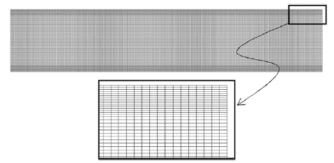
The same beam was analized using a mesh of 27000 four-noded plane stress rectangles for comparison purposes (Figure 3). Results for the plane stress analysis are labeled “PS” in the figures.

|
| Figure 2: Cantilever beam under point load |
|
| Figure 3: Mesh of 27000 4-noded plane stress rectangular elements for analysis of cantilever and simple supported beams |
| Composite material properties | |||
| Layer 1 | Layer 2 | Layer 3 | |
| (bottom) | (core) | (top) | |
| h [mm] | 6.6667 | 6.6667 | 6.6667 |
| E [MPa] | 2.19E5 | 2.19E3 | 2.19E5 |
| G [MPa] | 0.876E5 | 8.80E2 | 0.876E5 |
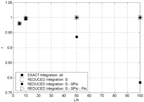
Figure 4 shows the ratio between the end node deflection obtained with the LRZ element () and with the plane stress quadrilateral () (i.e. ) versus the beam span-to-thickness ratio . Results for the LRZ element have been obtained using exact two-point integration for all terms of matrix (Eq.(27)) and a one-point reduced integration for the following three groups of matrices: ; and ; and , and (Eqs.(29b)).
Labels ``all', ``S', ``SPsi' and ``Psi' in Figures 4–7 refer to matrices , , and of Eq.(29a), respectively.
Results in Figure 4 clearly show that the exact integration of leads to shear locking as expected. Good (locking-free) results are obtained by one-point reduced integration of the three groups of matrices.
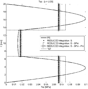
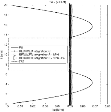
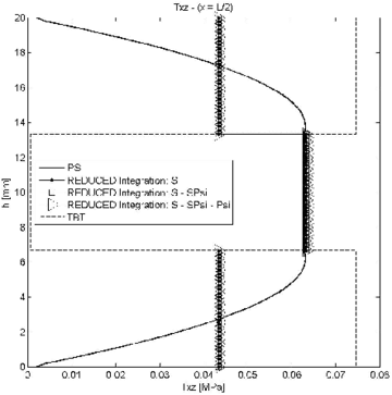
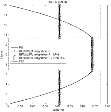
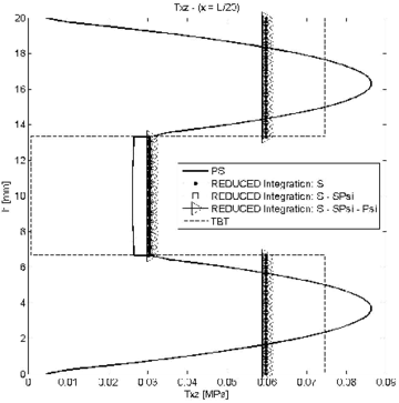
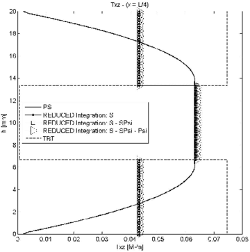
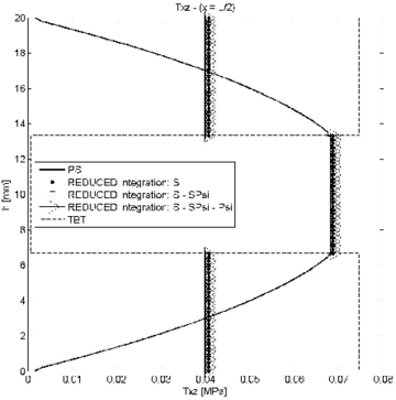
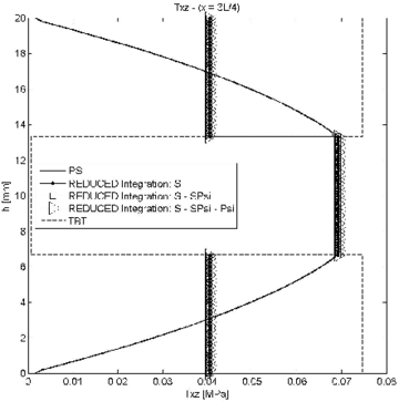
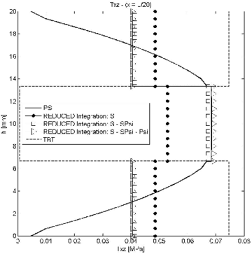
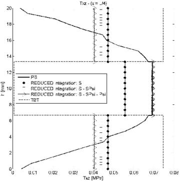
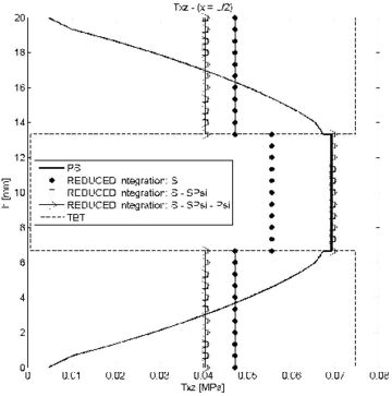
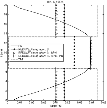
The influence of reduced integration in the distribution of the transverse shear stress was studied next for the three groups of matrices. Figures 5–7 show the thickness distribution of in sections located at distances and from the clamped end for span-to-thickness ratios of and 100. Results are compared with the plane stress solution and also with results obtained with a mesh of 300 standard 2-noded elements based on laminated Timoshenko beam theory (labelled TBT in the figures). All TBT results presented in the paper have been used with a simple shear correction factor of . Indeed a more accurate value of the shear correction factor in TBT can be used for laminated sections [28].
|
| Figure 4:' ratio versus for cantilever under point load analyzed with the LRZ element. Labels ``all', , and refer to matrices , and , respectively |
|
|
| (a) | (b) |
|
|
| (c) | (d) |
| Figure 5: Symmetric 3-layered cantilever thick beam under end point load. Thickness distribution of shear stress for at different sections | |
|
|
| (a) | (b) |
|
|
| (c) | (d) |
| Figure 6: Symmetric 3-layered cantilever thick beam under end point load. Thickness distribution of shear stress for at different sections | |
|
|
| (a) | (b) |
|
|
| (c) | (d) |
| Figure 7: Symmetric 3-layered cantilever thick beam under end point load. Thickness distribution of transverse shear stress for at different sections | |
The conclusion is that for small values of the reduced or exact reduced integration of matrix leads to similar results. For slender beams, however, results obtained using reduced integration for ; and ; and , and are different. Slightly more accurate results are obtained with the second choice for the section at and (Figure 7b).
In conclusion, we recommend using a reduced one-point integration for matrices and , while matrix should be integrated with a 2-point quadrature.
6 CONVERGENCE STUDY
The same three-layered cantilever beam of Figure 2 was studied next for three different set of thickness and material properties for the three layers as listed in Table 2. Material A is the more homogeneous one, while material C is clearly the more heterogeneous.
The problem was studied with six meshes of LRZ elements ranging from 5 to 300 elements. Tables 3–5 show the convergence with the number of elements for the deflection and function at the beam end, the maximum axial stress at the end section and the maximum shear stress at the mid section.
| Material properties | ||||
| Layer 1(bottom) | Layer 2 (core) | Layer 3 (top) | ||
| Composite A | h [mm] | 6.66 | 6.66 | 6.66 |
| E [MPa] | 4.40E5 | 2.19E4 | 2.19E5 | |
| G [MPa] | 2.00E5 | 8.80E3 | 8.76E4 | |
| Composite B | h [mm] | 6.66 | 6.66 | 6.66 |
| E [MPa] | 2.19E5 | 2.19E3 | 2.19E5 | |
| G [MPa] | 8.76E4 | 8.80E2 | 8.76E4 | |
| Composite C | h [mm] | 2 | 16 | 2 |
| E [MPa] | 7.30E5 | 7.30E2 | 2.19E5 | |
| G [MPa] | 2.92E5 | 2.20E2 | 8.76E4 | |
| at | |||
| Number of | Composites | ||
| elements | A | B | C |
| 5 | 1.800 | 9.588 | 42.289 |
| 10 | 0.506 | 2.901 | 19.277 |
| 25 | 0.0860 | 0.499 | 4.913 |
| 50 | 0.0191 | 0.123 | 1.406 |
| 100 | 0.0048 | 0.031 | 0.339 |
| 300 | 0.0000 | 0.0000 | 0.0000 |
| at | |||
| Number of | Composites | ||
| elements | A | B | C |
| 5 | 0.040 | 8.563 | 36.113 |
| 10 | 0.003 | 1.814 | 8.042 |
| 25 | 0.000 | 0.259 | 0.328 |
| 50 | 0.000 | 0.063 | 0.033 |
| 100 | 0.000 | 0.016 | 0.007 |
| 300 | 0.000 | 0.000 | 0.000 |
| (a) | |||
| at | |||
| Number of | Composites | ||
| elements | A | B | C |
| 5 | 0.568 | 6.923 | 18.239 |
| 10 | 0.076 | 2.704 | 12.437 |
| 25 | 0.013 | 0.568 | 4.266 |
| 50 | 0.003 | 0.131 | 1.095 |
| 100 | 0.001 | 0.029 | 0.250 |
| 300 | 0.000 | 0.000 | 0.000 |
| (b) | |||
| at | |||
| Number of | Composites | ||
| elements | A | B | C |
| 5 | 7.020 | 19.283 | 50.938 |
| 10 | 0.352 | 5.176 | 20.602 |
| 25 | 0.052 | 0.888 | 3.408 |
| 50 | 0.010 | 0.210 | 0.707 |
| 100 | 0.003 | 0.049 | 0.147 |
| 300 | 0.000 | 0.000 | 0.000 |
Convergence is measured by the relative error defined (in absolute value) as
|
|
(30) |
where and are the values of the magnitude of interest obtained using the finest grid (300 elements) and the th mesh (), respectively.
Results clearly show that convergence is always slower for the heterogeneous material case, as expected.
For a mesh of 25 elements the errors for all the magnitudes considered are less than 1% for materials A and B. For material C the maximum error does not exceed 5% (Table 5). For the 50 element mesh errors of the order of 1% or less were obtained in all cases.
Results for a 10 element mesh are good for material A (errors less than 0.4%), relatively good for material B (errors less than around ) and unacceptable for material C (errors ranging from around 8% to 20%
7 EXAMPLES OF APPLICATION
7.1 Three-layered thick cantilever beam with non symmetric material properties
We present results for a laminated thick cantilever beam under an end point load. The material properties are those of Composite C in Table 2. The span-to-thickness ratio is .
For the laminated sandwich considered the core is eight times thicker than the face sheets. In addition, the core is three orders of magnitude more compliant than the bottom face sheet. Moreover, the top face sheet has the same thickness as the bottom face sheet, but is about three times stiffer. Note that this laminate does not possess material symmetry with respect to the mid-depth reference axis. The high heterogeneity of this stacking sequence is very challenging for the beam theories considered herein to model adequately.
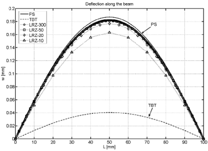
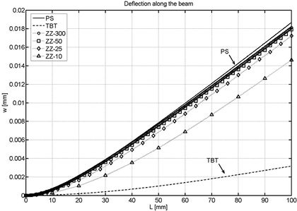
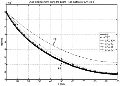
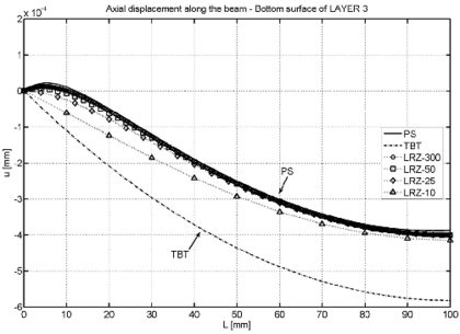
As in previous section, the legend caption PS denotes the reference solution obtained with the structured mesh of 27000 four-noded plane stress quadrilaterals shown in Figure 3. TBT denotes the solution obtained with a mesh of 300 2-noded beam elements based on standard laminated Timoshenko beam theory. LRZ-300, LRZ-50, LRZ-25, LRZ-10 refer to the solution obtained with the LRZ beam element using meshes of 300, 50, 25 and 10 elements, respectively.
Figure 8 shows the deflection values along the beam length. Very good agreement with the plane stress solution is obtained already for the LRZ-50 mesh as expected from the conclusions of the previous section.
TBT results are considerable stiffer. The difference with the reference solution is about six times stiffer for the end deflection value.
Figure 9 shows the distribution of the axial displacements at the upper and lower surfaces of layer 3 (top layer) along the beam length. Excellent results are again obtained with the 50 element mesh. The TBT results are far from the correct ones.
|
| Figure 8: Non symmetric 3-layered cantilever thick beam under end point load (). Distribution of the vertical deflection for different theories and meshes |
|
|
| (a) | (b) |
| Figure 9: Non symmetric 3-layered cantilever thick beam under end point load (). Axial displacement at the upper and lower surfaces of the top layer (layer 3) | |
|

|
| (a) | (b) |
| |
| (c) | |
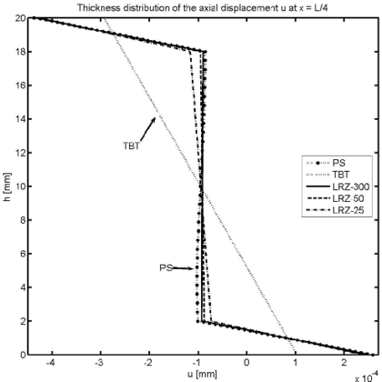
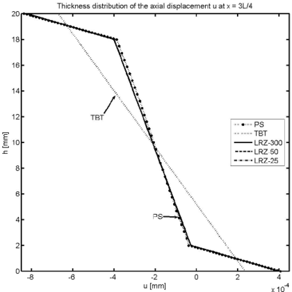
| Figure 10: Non symmetric 3-layered cantilever thick beam under end point load (). Thickness distribution of the axial displacement at (a), (b) and (c) | |
Figure 10 shows the thickness distribution for the axial displacement at sections located at distances and from the clamped end. Results for the LRZ element (LRZ-25, LRZ-50 and LRZ-300) are in good agreement with the reference solution. The TBT results have the standard linear distribution which is far from the correct zigzag results.
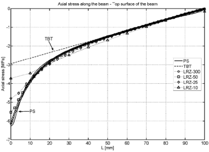
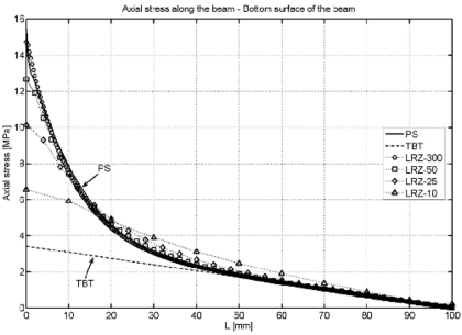
Figure 11 shows the distribution along the beam length of the axial stress at the top and bottom surfaces of the beam cross section. Very good agreement between the reference PS solution and the LRZ-50 and LRZ-300 results is obtained. Results for the LRZ-25 mesh compare reasonably well with the PS solution except in the vicinity of the clamped edge. This error is corrected for the LRZ-50 and LRZ-300 meshes. The TBT results yield a linear distribution of the axial stress along the beam, as expected. This introduces large errors in the axial stress values in the vicinity of the clamped edge, as clearly shown in Figure 11.
|
|
| (a) | (b) |
| Figure 11: Non symmetric 3-layered cantilever thick beam under end point load (). Axial stress at upper (a) and lower (b) surfaces of the cross section along the beam length | |
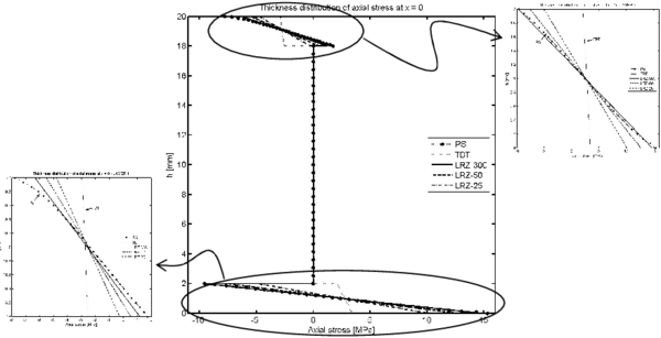
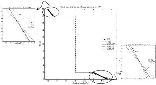
Figures 12 and 13 show the thickness distribution for the axial stress at the clamped section and at the center of the beam. LRZ results agree quite well with those of the reference solution. TBT results have an erroneous stress distribution for the top and bottom layers at the clamped end. These differences are less important for the central section.
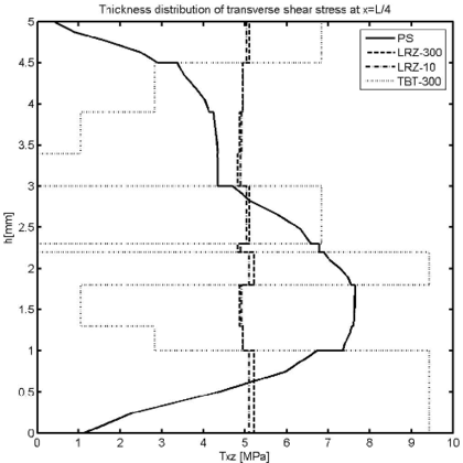
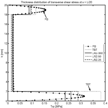
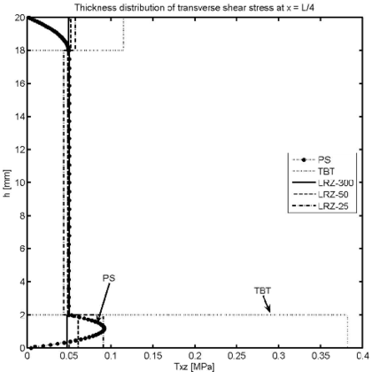
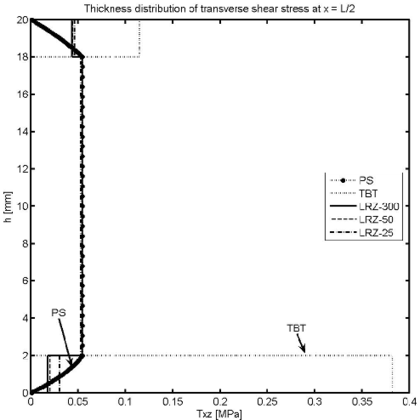
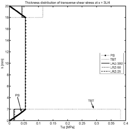
Figure 14 shows the thickness distribution for the transverse shear stress at different sections ( and ). LRZ results provide an accurate estimate of the average transverse shear stress value for each layer. The distribution of across the thickness can be substantially improved by using the equilibrium equations for computing “a posteriori” as explained in Section 7.3.
TBT results are acceptable for the central layer and clearly overestimate the transverse shear stress in sections far from the clamped end.
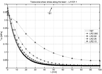
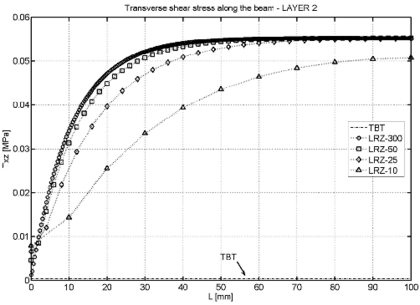
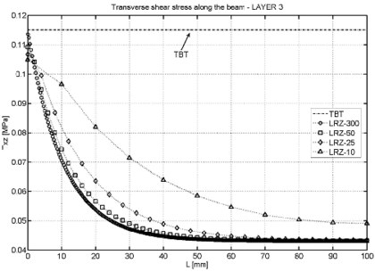
LRZ and TBT results for the distribution of the (constant) tangential shear stress for each of the three layers along the beam length are shown in Figure 15. TBT results are clearly inaccurate (except for the values at the clamped edge).
|
| Figure 12: Non symmetric 3-layered cantilever thick beam under end point load (). Thickness distribution of the axial stress at |
|
| Figure 13: Non symmetric 3-layered cantilever thick beam under end point load (). Thickness distribution of the axial stress at |
|
|
| (a) | (b) |
|
|
| (c) | (d) |
| Figure 14: Non symmetric 3-layered cantilever thick beam under end point load (). Thickness distribution of transverse shear stress at (a), (b), (c) and (d) | |
7.2 Three-layered simple supported (SS) thick beams under uniform load
The next example is the analysis of a three-layered simple supported thick beam under a uniformly distributed load of unit value (). The material properties and the thickness for the three layers are shown in Table 6. The material has a non symmetric distribution with respect to the beam axis. An unusually low value for the shear modulus of the core layer has been taken, thus reproducing the effect of a damaged material in this zone. The span-to-thickness ratio is . Results obtained with the LRZ element are once more compared with those obtained with a mesh of 300 2-noded TBT elements and with the mesh of 27000 4-noded plane stress (PS) rectangles shown in Figure 3. The PS solution has been obtained by fixing the vertical displacement of all nodes at the end sections and the horizontal displacement of the mid-line node at and to a zero value. This way of approximating a simple support condition leads to some discrepancies between the PS results and those obtained with beam theory.
No advantage of the symmetry of the problem for the discretization has been taken.
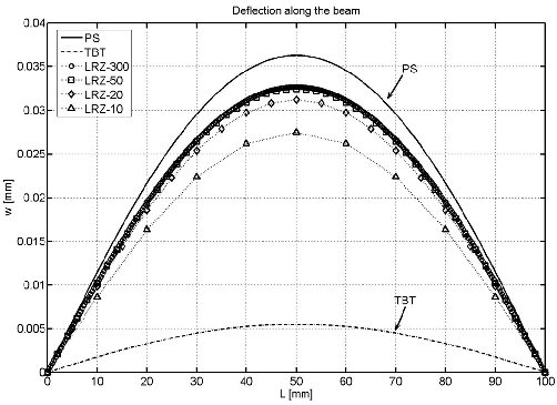
Figure 16 shows the distribution of the vertical deflection for the different methods. The error in the “best” maximum central deflection value versus the “exact” PS solution is 12% The discrepancy is due to the difference in the way the simple support condition is modelled in beam and PS theories, as well as to the limitations of beam theory to model accurately very thick beams. TBT results are inaccurate, as expected.
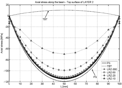
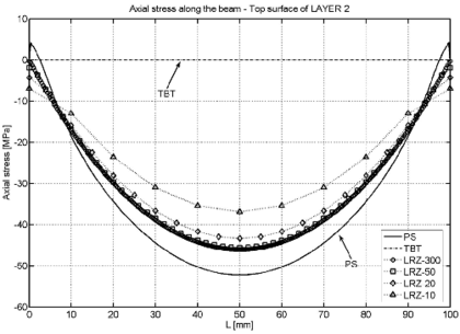
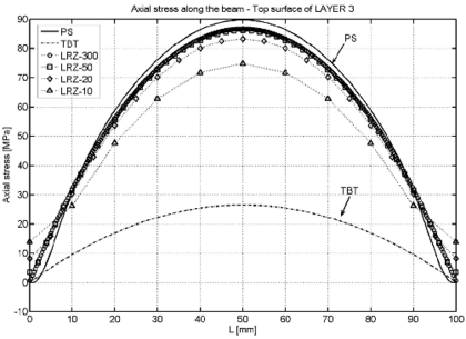
Figure 17 shows the distribution of the axial stress along the beam for the top surface of the second and third layer.
The accuracy of the LRZ results is remarkable with a maximum error of 10% despite of the modeling limitations mentioned above. TBT results are incorrect.
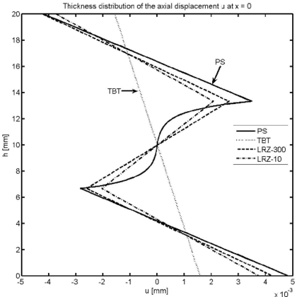
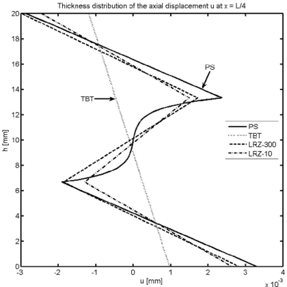
Figure 18 shows the thickness distribution of the axial displacement at the left end section and at . The LRZ element captures very well the zigzag shape of the axial displacement field even for a coarse mesh of 10 elements. The TBT element yields an unrealistic linear distribution.
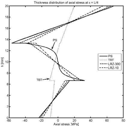
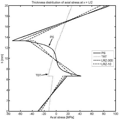
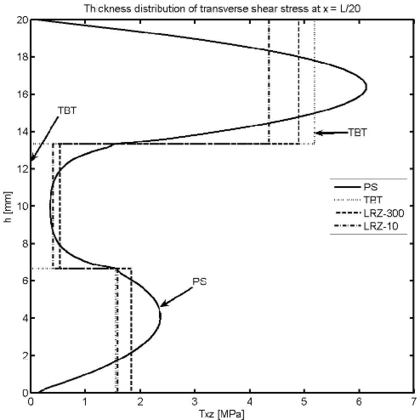
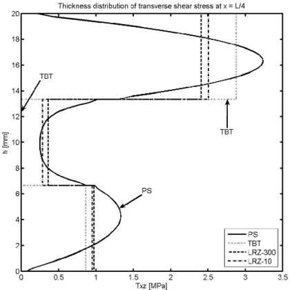
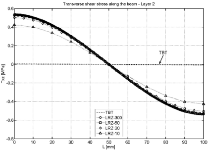
Figures 19 and 20 show the thickness distribution of the axial stress and the transverse shear stress at the left end and mid sections. The accuracy of the LRZ results is again noticeable (even for the coarse 10 element mesh). The TBT element fails to capture the zigzag distribution of the axial stress (Figure 19) and gives a wrong value of almost zero shear stress at the core layer for the two sections chosen (Figure 20).
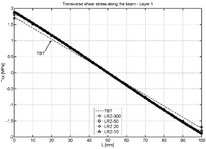
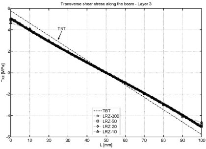
Figure 21 shows the distribution of the shear stress along the beam for each of the three layers obtained with the LRZ and TBT elements. TBT results are accurate for the first and third layer but are wrong for the core layer.
Figure 22 shows a similar set of results for a moderately thick SS beam () and the same material properties. Results shown are the distribution along the beam of the deflection and the axial stress at the top surface of layer 2. The accuracy of the LRZ element is again noticeable.
| Thickness and material properties | |||
| Layer 1 (bottom) | Layer 2 (core) | Layer 3 (top) | |
| h [mm] | 6.6666 | 6.6666 | 6.6666 |
| E [MPa] | 2.19E | 5.30E | 7.30E |
| G [MPa] | 8.76E | 2.90E | 2.92E |
|
| Figure 16: Non symmetric 3-layered SS thick beam under uniformly distributed load . Distribution of vertical deflection along the beam length |
|
|
| (a) | (b) |
| Figure 17: Non symmetric 3-layered SS thick beam under uniformly distributed load . Distribution of axial stress at upper surface of layer 2 (a) and layer 3 (b) | |
|
|
| (a) | (b) |
| Figure 18: Non symmetric 3-layered SS thick beam under uniformly distributed load . Thickness distribution of axial displacement at (a) and at (b) | |
|
|
| (a) | (b) |
| Figure 19: Non symmetric 3-layered SS thick beam under uniformly distributed load . Thickness distribution of axial stress at (a) and at (b) | |
|
|
| (a) | (b) |
| Figure 20: Non symmetric 3-layered SS thick beam under uniformly distributed load . Thickness distribution of the shear stress at (a) and at (b) | |
|
|
| (a) | (b) |
| |
| (c) | |
| Figure 21: Non symmetric 3-layered SS thick beam under uniformly distributed load . LRZ and TBT results for the distribution of along the beam for layer 1 (a), layer 2 (b) and layer 3 (c) | |
7.3 Non-symmetric ten-layered clamped slender beam under uniformly distributed loading
We present results for a ten-layered clamped slender rectangular beam ( mm, mm, mm, ) under uniformly distributed loading ( KN/mm). The composite material has the non-symmetric distribution across the thickness shown in Table 7.
| (a) | ||
| Layer | Material | |
| 1 | 0.5 | IV |
| 2 | 0.6 | I |
| 3 | 0.5 | V |
| 4 | 0.4 | III |
| 5 | 0.7 | IV |
| 6 | 0.1 | III |
| 7 | 0.4 | II |
| 8 | 0.5 | V |
| 9 | 0.3 | I |
| 10 | 1 | II |
| (b) | ||
| Material | E [MPa] | G [MPa] |
| I | 2.19e5 | 0.876e5 |
| II | 7.3e5 | 2.92e5 |
| III | 0.0073e5 | 0.0029e5 |
| IV | 5.3e5 | 2.12e5 |
| V | 0.82e5 | 0.328e5 |
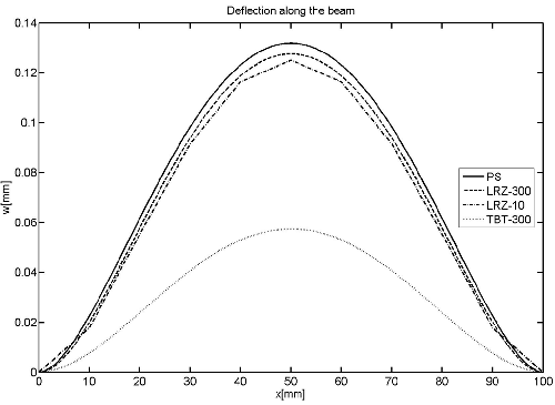
Figure 23 shows results for the deflection along the beam for LRZ meshes with 10 and 300 elements (LRZ-10 and LRZ-300). Results obtained with a mesh of 27.000 4-noded plane stress quadrilaterals and with a mesh of 300 TBT elements are also shown for comparison. Note the accuracy of the coarse LRZ-10 mesh and the erroneous results of the TBT solution.
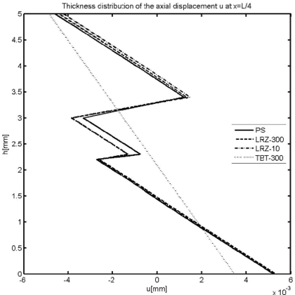
Figure 24 shows the thickness distribution of the axial displacement and the axial stress () for the section at . The accuracy of the LRZ results is once more remarkable.
|
| Figure 23: 10-layered clamped slender beam under uniform loading. Distribution of the deflection along the beam |
|
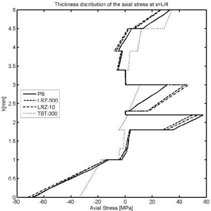
|
| (a) | (b) |
| Figure 24: 10-layered clamped slender beam under uniform loading. Thickness distribution of axial displacement (a) and axial stress (b) for | |
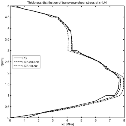
Figure 25 shows the thickness distribution of the transverse shear stress at . Results in Figure 25a show the values directly obtained with the LRZ-10 and LRZ-300 meshes. These results are clearly better than those obtained with the TBT element but only coincide in an average sense with the plane stress FEM solution.
LRZ results for the thickness distribution of can be much improved by computing “a posteriori” from the axial stress field using the equilibrium equation
|
|
(31) |
The transverse shear stress at a point across the thickness with coordinate is computed by integrating Eq.(31) as
|
|
(32) |
where
|
|
(33) |
is the axial force (per unit width) resulting from the thickness integration of between the coordinates and .
The space derivative of in Eq.(32) is computed at a node as
|
|
(34) |
where () and () are the element length and the value of at elements and adjacent to node , respectively. A value of is taken. It is remarkable that the method yields automatically .
Results for obtained with this procedure are termed LRZ-10- and LRZ-300- in Figure 25. We note the accuracy of the “recovered” thickness distribution for , even for the coarse mesh of 10 LRZ elements.
7.4 Modeling of delamination with the LRZ element
Prediction of delamination in composite laminated beams is a challenge for all beam models. A method for predicting delamination in beams using a Hermitian zigzag theory was presented in [26,27]. A sub-laminate approach is used for which the number of kinematic unknowns depends of the number of physical layers. This increases the number of variables but it yields the correct an accurate transverse shear stress distribution without integrating the equilibrium equations.
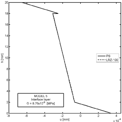
Delamination effects in composite laminated beams can be effectively reproduced with the LRZ element without introducing additional kinematic variables. The delamination model simply implies introducing a very thin “interface layer” between adjacent material layers in the actual composite laminated section. Delamination is produced when the material properties of the interface layer are drastically reduced to almost a zero value in comparison with those of the adjacent layers due to interlamina failure. This simple delamination model allows the LRZ element to take into account the reduction of the overall beam stiffness due to the failure of the interface layer leading to an increase in the deflection and rotation field. Moreover, the LRZ element can also accurately represent the jump in the axial displacement field across the interface layer and the change in the axial and tangential stress distributions over the beam sections as delamination progresses.
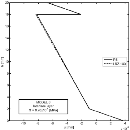
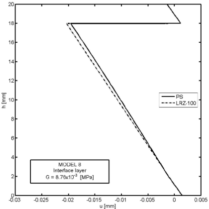
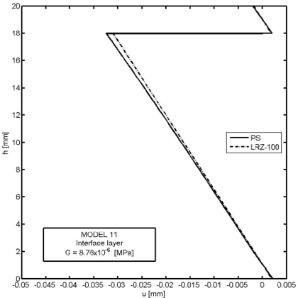
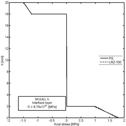
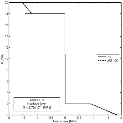
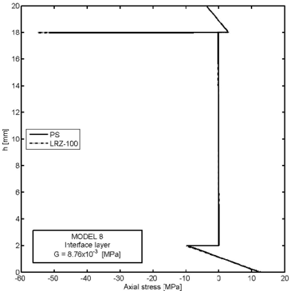
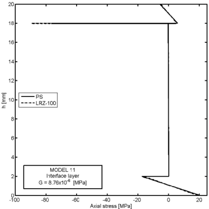
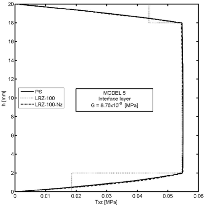
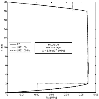
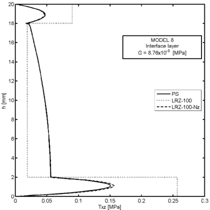
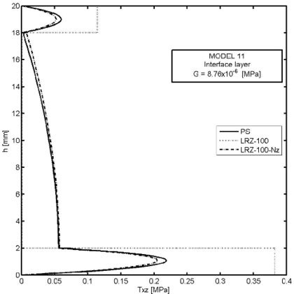
Figures 26–30 show an example of the capabilities of the LRZ beam element to model delamination. The problem represents the analysis of a cantilever thick rectangular beam () under an end point load. The beam section has three layers of composite material with properties shown in Table 8. Delamination between the upper and core layers has been modelled by introducing a very thin interface layer ( mm) between these two layers (Figure 26). The initial properties of the interface layer coincide with those of the upper layer. Next, the shear modulus value for the interface layer has been progressively reduced up to 11 orders of magnitude from MPa (Model 1) to MPa (Model 12) (Table 9).
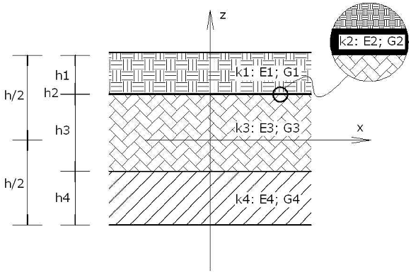
|
| Figure 26: Modeling of interface layer for delamination study in 3-layered thick cantilever beam () under end point load |
| Composite material | ||||
| Layer 1 | Layer 2 | Layer 3 | Layer 4 | |
| h [mm] | 2 | 0.01 | 16 | 2 |
| E [MPa] | 2.19E5 | 2.19E5 | 0.0073E5 | 7.30E5 |
| G [MPa] | 0.876E5 | G2 | 0.0029E5 | 2.92E5 |
| Model | G2 | Model | G2 | Model | G2 |
| 1 | 8.76E+004 | 5 | 8.76E+000 | 9 | 8.76E-004 |
| 2 | 8.76E+003 | 6 | 8.76E-001 | 10 | 8.76E-005 |
| 3 | 8.76E+002 | 7 | 8.76E-002 | 11 | 8.76E-006 |
| 4 | 8.76E+001 | 8 | 8.76E-003 | 12 | 8.76E-007 |
We note that the reduction of the shear modulus has been applied over the whole beam length in this case. However it can applied in selected beam regions as appropriate.
Figure 27 shows results for the end deflection in terms of the shear modulus value of the interface layer for the LRZ-100 mesh. Note that the deflection increases one order of magnitude versus the non-delaminated case. It is also interesting that the end deflection does not change after the shear modulus of the interface layer is reduced beyond eight orders of magnitude (results for Model 9 in Figure 27). Results agree reasonably well (error ) with those obtained with the plane stress model of Figure 3 introducing a similar reduction in the shear modulus of an ad hoc interface layer.
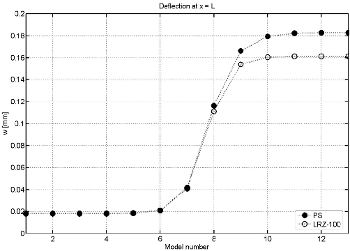
|
| Figure 27: Delamination study in 3-layered cantilever beam under end point load. Evolution of end deflection with the shear modulus value for the interface layer LRZ-100 results and PS solution |
Figure 28 shows the thickness distribution for the axial displacement at the mid section for four decreasing values of the shear modulus at the interface layer: and MPa. The jump of the axial displacement across the thickness at the interface layer during delamination is well captured. We again note that the displacement jump at the interface layer remains stationary after a reduction of the material properties in that layer of six orders of magnitude. Results agree well with the plane stress solution also shown in the figure.
Figure 29 shows the thickness distribution of the axial stress () for the same four decreasing values of the shear modulus at the interface layer. The effect of delamination in the stress distribution is clearly visible. Once again the LRZ-100 results agree well with the plane stress solution.
Figure 30 finally shows the thickness distribution for the transverse shear stress at for the same four values of the shear modulus at the interface layer. The three graphs show the PS results, the LRZ-100 results and the solution obtained by integrating the equilibrium equation (via Eqs.(31)–(34)) using the LRZ-100 results. Note the accuracy of the later solution versus the standard LRZ-100 results as delamination develops and the transverse shear stress progressively vanishes at the interface layer.
Similar good results for predicting the delamination and the thickness distribution of the axial and transverse shear stresses are obtained over the entire beam length.
The example shows clearly the capability of the LRZ element to model a complex phenomenon such as delamination in composite laminated beams without introducing additional kinematic variables. More evidence of the good behaviour of the LRZ beam element for predicting delamination in beams are reported in [29].
8 CONCLUSIONS
We have presented a simple and accurate 2-noded beam element based on the combination of the refined zigzag beam theory proposed by Tessler et al. [22]. The element has four degrees of freedom per node (the axial displacement, the deflection, the rotation and the amplitude of the zigzag function). A standard linear interpolation is used for all variables. The resulting LRZ beam element is shear locking-free and has shown an excellent behaviour for analysis of thick and thin composite laminated beams with clamped and simple supported conditions. Numerical results agree in practically all cases with those obtained with a two-dimensional plane-stress FEM using a far larger number of degrees of freedom. It is remarkable that the zigzag distribution of the axial displacement and the axial stress across the thickness, typical of composite laminated beams, is very accurately captured with the basic approximation chosen. The possibilities of the new LRZ beam element for predicting delamination effects has been demonstrated in a simple but representative example of application.
ACKNOWLEDGEMENTS
This research was partially supported by project SEDUREC of the Consolider Programme of the Ministerio de Educación y Ciencia of Spain.
REFERENCES
[1] Timoshenko S.P. and Woinowsky-Krieger S., Theory of Plates and Shells. McGraw-Hill, New York, 3rd Edition, 1959.
[2] Timoshenko S. On the correction for shear of differential equations for transverse vibrations of prismatic bars. Philosophical Magazine Series, Vol. 41, pp. 744-746, 1921.
[3] Liu D. and Li X. An overall view of laminate theories based on displacement hypothesis. Journal of Composite Materials, Vol. 30(14), pp. 1539-1561, 1996.
[4] Reddy, J.N., Mechanics of laminated composite plates and shells. Theory and analysis. 2nd Edition, CRC Press, Boca Raton, 2004.
[5] Owen D.R.J. and Li Z.H., A refined analysis of laminated plates by finite element displacement methods. Part I. Fundamentals and static analysis. II Vibration and stability. Comp. Struct, Vol. 26, pp. 907–923, 1987.
[6] Botello, S. Oñate, E. and Canet, J.M., A layer-wise triangle for analysis of laminated composite plates and shells. Computers and Structures, Vol. 70, 635–646, 1999.
[7] Di Sciuva M. Bending, vibration and buckling of simply supported thick multilayered orthotropic plates: an evaluation of a new displacement model. Journal of Sound and Vibration, Vol. 105, pp. 425-442, 1986.
[8] Murakami H. Laminated composite plate theory with improved in-plane responses. ASME Journal of Applied Mechanics, Vol. 53, pp. 661-666, 1986.
[9] Aitharaju V.R. and Averill R.C., An assessment of zig-zag kinematic displacement models for the anlaysis of laminated composites. Mech. Composite Mat. and Struct., 6, 1–26, 1999a.
[10] Aitharaju V.R. and Averill R.C., C zig-zag finite element for analysis of laminated composite beams. J. Engineering Mechanics, ASCE, 323–330, 1999b.
[11] Li X. and Liu D. An interlaminar shear stress continuity theory for both thin and thick composite laminates. J. Appl. Mech., 59, 502–509, 1992.
[12] Di Sciuva M. An improved shear-deformation theory for moderately thick multilayered anisotropic shells and plates. J. Appl. Mech. 54, 589–594, 1987.
[13] Toledano A and Murakami H. A higher-order laminate plate theory with improved in-plane response. Int. J. Solids and Struct., 23, 111–131, 1987b.
[14] Cho M. and Parmerter R.R. Efficient higher order composite plate theory for general laminations configuration. AIAA J., 31, 1299–1306, 1993.
[15] Kapuria, S., Dumir, P.C., Ahmed, A. and Alam, N. Finite element model of efficient zigzag theory for static analysis of hybrid piezoelectric beams, Computational Mechanics, Vol. 34 (6), pp. 475–483, 2004.
[16] Averill R.C. Static and dynamic response of moderately thick laminated beams with damage. Composites Engineering, Vol. 4(4), pp. 381-395, 1994.
[17] Averill R.C. and Yuen Cheong Yip. Development of simple, robust finite elements based on refined theories for thick laminated beams. Computers & Structures, Vol. 59(3), pp. 529-546, 1996.
[18] Alam N.M. and Upadhyay N.Kr. Finite element analysis of laminated composite beams for zigzag theory using MATLAB. Int. J. of Mechanics and Solids, Vol. 5(1), pp. 1–14, 2010.
[19] Savoia M. On the accuracy of one-dimensional models for multilayered composite beams. Int. J. Solids Struct., Vol. 33, pp. 521-44, 1996.
[20] Kapuria S, Dumir P.C. and Jain N.K. Assessment of zigzag theory for static loading, buckling, free and forced response of composite and sandwich beams. Composite Structures, Vol. 64, pp. 317-27, 2004.
[21] Carrera, E. Historical review of zigzag theories for multilayered plate and shell. Applied Mechanics Review, 56(3), 287–308, 2003.
[22] Tessler, A., Di Sciuva M. and Gherlone, M. A refined zigzag beam theory for composite and sandwich beams. J. of Composite Materials, Vol. 43, 1051–1081, 2009.
[23] Tessler, A., Di Sciuva M. and Gherlone, M. A consistent refinement of first-order shear-deformation theory for laminated composite and sandwich plates using improved zigzag kinematics. J. of Mechanics of Materials and Structures, 5(2), 341–367, 2010.
[24] Gherlone, M., Tessler, A. and Di Sciuva M. C beam element based on the refined zigzag theory for multilayered composite and sandwich laminates. Composite Structures. Accepted for publication, May 2011.
[25] Oñate, E., Eijo, A. and Oller, S. Two-noded beam element for composite and sandwich beams using Timoshenko theory and refined zigzag kinematics. Publication CIMNE PI346, CIMNE, Barcelona, October 2010.
[26] Di Sciuva M. and Gherlone, M. A global/local third-order Hermitian displacement field with damaged interfaces and transverse extensibility: FEM formulation. Composite Structures, 59(4), 433-444, 2003.
[27] Di Sciuva M. and Gherlone, M. Quasi-3D static and dynamic analysis of undamaged and damaged sandwich beams. Journal of Sandwich Structures & Materials, 7(1), 31–52, 2005.
[28] Oñate, E. Structural Analysis with the Finite Element Method. Vol. 2 Beams, Plates and Shells. CIMNE-Springer, 2011.
[29] Oñate, E., Eijo, A. and Oller, S. Modeling of delamination in composite laminated beams using a two-noded beam element based in refined zigzag theory. Publication CIMNE, PI367, November 2011.
Document information
Published on 01/01/2012
DOI: 10.1016/j.cma.2011.11.023
Licence: CC BY-NC-SA license
Share this document
Keywords
claim authorship
Are you one of the authors of this document?
