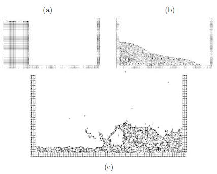
| Line 468: | Line 468: | ||
In above <math>B</math> is the strain rate matrix and <math display="inline">{\boldsymbol m} = [1,1,0]^T</math> for 2D problems. | In above <math>B</math> is the strain rate matrix and <math display="inline">{\boldsymbol m} = [1,1,0]^T</math> for 2D problems. | ||
| − | ===3.4 Fractional Step Method for Fluid-Structure Interaction Analysis== | + | ===3.4 Fractional Step Method for Fluid-Structure Interaction Analysis=== |
The starting point of the iterative algorithm are the variables at time n in the fluid domain (<math>^nF</math>). The sought variables are the variables at time <math>n+1 (^{n+1}F)</math>. For the sake of clarity we will skip the upper left index n + 1 for all variables, i.e. | The starting point of the iterative algorithm are the variables at time n in the fluid domain (<math>^nF</math>). The sought variables are the variables at time <math>n+1 (^{n+1}F)</math>. For the sake of clarity we will skip the upper left index n + 1 for all variables, i.e. | ||
| Line 484: | Line 484: | ||
A simple iterative algorithm is obtained by splitting the pressure from the momentum equations as follows | A simple iterative algorithm is obtained by splitting the pressure from the momentum equations as follows | ||
| − | + | <span id='eq-28'></span> | |
{| class="formulaSCP" style="width: 100%; text-align: left;" | {| class="formulaSCP" style="width: 100%; text-align: left;" | ||
|- | |- | ||
| Line 492: | Line 492: | ||
| style="text-align: center;" | <math>\bar {\boldsymbol v}^* = \bar {\boldsymbol v}^n -\Delta t {\boldsymbol M}^{-1}[{\boldsymbol K} {\boldsymbol v}^{n+1,j-1} -{\boldsymbol G} \mathbf{p}^n - {\boldsymbol f}^{n+1}]</math> | | style="text-align: center;" | <math>\bar {\boldsymbol v}^* = \bar {\boldsymbol v}^n -\Delta t {\boldsymbol M}^{-1}[{\boldsymbol K} {\boldsymbol v}^{n+1,j-1} -{\boldsymbol G} \mathbf{p}^n - {\boldsymbol f}^{n+1}]</math> | ||
|} | |} | ||
| − | | style="width: 5px;text-align: right;white-space: nowrap;" | ( | + | | style="width: 5px;text-align: right;white-space: nowrap;" | (28) |
|} | |} | ||
| − | + | <span id='eq-29'></span> | |
{| class="formulaSCP" style="width: 100%; text-align: left;" | {| class="formulaSCP" style="width: 100%; text-align: left;" | ||
|- | |- | ||
| Line 502: | Line 502: | ||
| style="text-align: center;" | <math>\bar{\boldsymbol v}^{n+1,j}= \bar{\boldsymbol v}^* + \Delta t {\boldsymbol M}^{-1}{\boldsymbol G}\delta \bar{\boldsymbol p}</math> | | style="text-align: center;" | <math>\bar{\boldsymbol v}^{n+1,j}= \bar{\boldsymbol v}^* + \Delta t {\boldsymbol M}^{-1}{\boldsymbol G}\delta \bar{\boldsymbol p}</math> | ||
|} | |} | ||
| − | | style="width: 5px;text-align: right;white-space: nowrap;" | ( | + | | style="width: 5px;text-align: right;white-space: nowrap;" | (29) |
|} | |} | ||
| − | where <math display="inline">\delta \bar{\boldsymbol p}</math> denotes a pressure increment. In above equations and in the following | + | where <math display="inline">\delta \bar{\boldsymbol p}</math> denotes a pressure increment. In above equations and in the following the left upper index <math display="inline">n</math> refers to values in the current application <math>^nV</math> whereas the right index <math display="inline">j</math> denotes an iteration number within each time step. |
| − | + | ||
| − | + | ||
| + | The value of <math display="inline">\bar {\boldsymbol v}^{n+1,j}</math> from Eq.([[#eq-28|28]]) is substituted now into Eq.([[#eq-25b|25]]) to give | ||
| + | <span id='eq-30'></span> | ||
| + | <span id='eq-30a'></span> | ||
{| class="formulaSCP" style="width: 100%; text-align: left;" | {| class="formulaSCP" style="width: 100%; text-align: left;" | ||
|- | |- | ||
| Line 520: | Line 521: | ||
where | where | ||
| − | + | <span id='eq-30b'></span> | |
{| class="formulaSCP" style="width: 100%; text-align: left;" | {| class="formulaSCP" style="width: 100%; text-align: left;" | ||
|- | |- | ||
Revision as of 12:01, 16 May 2019
Abstract
We present a general formulation for analysis of fluid-structure interaction problems using the particle finite element method (PFEM). The key feature of the PFEM is the use of a Lagrangian description to model the motion of nodes (particles) in both the fluid and the structure domains. Nodes are thus viewed as particles which can freely move and even separate from the main analysis domain representing, for instance, the effect of water drops. A mesh connects the nodes defining the discretized domain where the governing equations, expressed in an integral from, are solved as in the standard FEM. The necessary stabilization for dealing with the incompressibility of the fluid is introduced via the finite calculus (FIC) method. A fractional step scheme for the transient coupled fluid-structure solution is described. Examples of application of the PFEM to solve a number of fluid-structure interaction problems involving large motions of the free surface and splashing of waves are presented.
Keyword: Lagrangian formulation, fluid-structure, particle finite element.
1 Introduction
There is an increasing interest in the development of robust and efficient numerical methods for analysis of engineering problems involving the interaction of fluids and structures accounting for large motions of the fluid free surface and the existence of fully or partially submerged bodies. Examples of this kind are common in ship hydrodynamics, off-shore structures, spill-ways in dams, free surface channel flows, liquid containers, stirring reactors, mould filling processes, etc.
The movement of solids in fluids is usually analyzed with the finite element method (FEM) [20] using the so called arbitrary Lagrangian-Eulerian (ALE) formulation [3]. In the ALE approach the movement of the fluid particles is decoupled from that of the mesh nodes. Hence the relative velocity between mesh nodes and particles is used as the convective velocity in the momentum equations.
Typical difficulties of FSI analysis using the FEM with both the Eulerian and ALE formulation include the treatment of the convective terms and the incompressibility constraint in the fluid equations, the modelling and tracking of the free surface in the fluid, the transfer of information between the fluid and solid domains via the contact interfaces, the modelling of wave splashing, the possibility to deal with large rigid body motions of the structure within the fluid domain, the efficient updating of the finite element meshes for both the structure and the fluid, etc.
Most of these problems disappear if a Lagrangian description is used to formulate the governing equations of both the solid and the fluid domain. In the Lagrangian formulation the motion of the individual particles are followed and, consequently, nodes in a finite element mesh can be viewed as moving “particles”. Hence, the motion of the mesh discretizing the total domain (including both the fluid and solid parts) is followed during the transient solution.
In this paper we present an overview of a particular class of Lagrangian formulation developed by the authors to solve problems involving the interaction between fluids and solids in a unified manner. The method, called the particle finite element method (PFEM), treats the mesh nodes in the fluid and solid domains as particles which can freely move and even separate from the main fluid domain representing, for instance, the effect of water drops. A finite element mesh connects the nodes defining the discretized domain where the governing equations are solved in the standard FEM fashion. The PFEM is the natural evolution of recent work of the authors for the solution of FSI problems using Lagrangian finite element and meshless methods [1,7-10,17-19].
An obvious advantage of the Lagrangian formulation is that the convective terms disappear from the fluid equations. The difficulty is however transferred to the problem of adequately (and efficiently) moving the mesh nodes. Indeed for large mesh motions remeshing may be a frequent necessity along the time solution. We use an innovative mesh regeneration procedure blending elements of different shapes using an extended Delaunay tesselation [7-9]. Furthermore, this special polyhedral finite element needs special shape functions. In this paper, meshless finite element (MFEM) shape functions have been used [7].
The need to properly treat the incompressibility condition in the fluid still remains in the Lagrangian formulation. The use of standard finite element interpolations may lead to a volumetric locking defect unless some precautions are taken [3,20]. In our work the stabilization via a finite calculus (FIC) procedure has been chosen [12]. Recent applications of the FIC method for incompressible flow analysis using linear triangles and tetrahedra are reported in [5,12,13,14,15,18,19].
The layout of the paper is the following. In the next section the basic ideas of the PFEM are outlined. Next the basic equation for an incompressible flow using a Lagrangian description and the FIC formulation are presented. Then a fractional step scheme for the transient solution via standard finite element procedures is described. Details of the treatment of the coupled FSI problem are given. The procedures for mesh generation and for identification of the free surface nodes are briefly outlined. Finally, the efficiency of the particle finite element method (PFEM) is shown in its application to a number of FSI problems involving large flow motions, surface waves, moving bodies. etc.
2 The basis of the Particle Finite Element Method
Let us consider a domain containing both fluid and solid subdomains. The moving fluid particles interact with the solid boundaries thereby inducing the deformation of the solid which in turn affects the flow motion and, therefore, the problem is fully coupled.
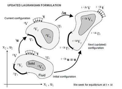
In the PFEM approach presented here, both the fluid and the solid domains are modelled using an updated Lagrangian formulation. That is, all variables in the fluid and solid domains are assumed to be known in the current configuration at time t. The new set of variables in both domains are sought for in the next or updated configuration at time (Figure 1). The finite element method (FEM) is used to solve the continuum equations in both domains. Hence a mesh discretizing these domains must be generated in order to solve the governing equations for both the fluid and solid problems in the standard FEM fashion. We note once more that the nodes discretizing the fluid and solid domains can be viewed as material particles which motion is tracked during the transient solution. This is useful to model the separation of water particles from the main fluid domain and to follow their subsequent motion as individual particles with an initial velocity and subject to gravity forces.
It is important to note once more that each particle is a material point characterized by the density of the solid or fluid domain to which it belongs. The mass of a given domain is obtained by integrating the density at the different material points over the domain.
The quality of the numerical solution depends on the discretization chosen as in the standard FEM. Adaptive mesh refinement techniques can be used to improve the solution in zones where large motions of the fluid or the structure occur.
|
| Figura 1: Updated lagrangian description for a continuum containing a fluid and a solid domain |
2.1 Basic steps of the PFEM
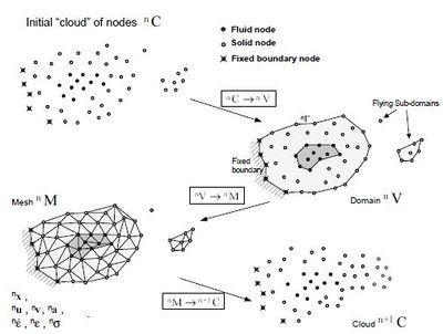
For clarity purposes we will define the collection or cloud of nodes () pertaining to the fluid and solid domains, the volume () defining the analysis domain for the fluid and the solid and the mesh () discretizing both domains. A typical solution with the PFEM involves the following steps.
- The starting point at each time step is the cloud of points in the fluid and solid domains. For instance denotes the cloud at time (Figure 2).
- Identify the boundaries for both the fluid and solid domains defining the analysis domain in the fluid and the solid. This is an essential step as some boundaries (such as the free surface in fluids) may be severely distorted during the solution process including separation and re-entering of nodes. The Alpha Shape method 4 is used for the boundary definition (see Section 7).
- Discretize the fluid and solid domains with a finite element mesh . In our work we use an innovative mesh generation scheme based on the extended Delaunay tesselation (Section 6)[7,8,10]
- Solve the coupled Lagrangian equations of motion for the fluid and the solid domains. Compute the relevant state variables in both domains at the next (updated) configuration for : velocities, pressure and viscous stresses in the fluid and displacements, stresses and strains in the solid. An overview of the coupled FSI algorithm is given in the next section.
- Move the mesh nodes to a new position where denotes the time , in terms of the time increment size. This step is typically a consequence of the solution process of step 4.
- Go back to step 1 and repeat the solution process for the next time step.
|
| Figura 2: Sequence of steps to update a “cloud” of nodes from time to time |
2.2 Overview of the coupled FSI algoritm
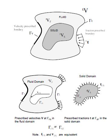
Figure 3 shows a typical domain V with external boundaries and where the velocity and the surface tractions are prescribed, respectively. The domain is formed by fluid () and solid () subdomains. Both subdomains interact at a common boundary where the surface tractions and the kinematic variables (displacements, velocities and acelerations) are the same for both subdomains. Note that both set of variables (the surface tractions and the kinematic variables) are equivalent in the equilibrium configuration.
|
| Figura 3: Split of the analysis domain into fluid and solid subdomains. Equality of surface tractions and kinematic variables at the common interface |
Let us define and the set of variables defining the kinematics and the stress-strain fields at the solid and fluid domains at time , respectively, i.e.
|
|
(1) |
|
|
(2) |
where is the nodal coordinate vector, , and are the vector of displacements, velocities and accelerations, respectively, , and are the strain vector, the strainrate (or rate of deformation) vectors and the Cauchy stress vector, respectively and and denote the variables in the fluid and solid domains, respectively. In the discretized problem, a bar over these variables will denote nodal values.
The coupled fluid-structure interaction (FSI) problem of Figure 3 will be solved using the following conceptual scheme:
- We assume that the variables in the solid and fluid domains at time and are known.
- Solve for the variables at the solid domain at time under prescribed surface tractions at the fluid-solid boundary .
- Solve for the variables at the fluid domain at time under prescribed surface tractions at the external boundary and prescribed velocities at the external and internal boundaries and , respectively.
Iterate between 2 and 3 until convergence.
The variables at the solid domain are found via the integration of the dynamic equations of motion in the solid written as
|
|
(3) |
where , and denote the mass matrix, the internal node force vector and the external nodal force vector at the solid domain. The time integration of Eq.(3) is performed using a standard Newmark method. An incremental iterative scheme is implemented within each time step to account for non linear geometrical and material effects.
The FEM solution of the variables in the (incompressible) fluid domain implies solving the momentum and incompressibility equations. As mentioned above this is not such as simple problem as the incompressibility condition limits the choice of the FE approximations for the velocity and pressure to overcome the well known divstability conditions [20]. In our work we use a stabilized FEM based on the Finite Calculus approach which allows to use a linear approximation for the velocity and pressure variables. Details of the FEM/FIC formulation used are given in the next section.
Figure 4 shows a typical example of a PFEM solution in 2D. The pictures correspond to the analysis of the problem of breakage of a water column [10,13]. Figure 4a shows the initial grid of four node rectangles discretizing the fluid domain and the solid walls. Boundary nodes identified with the Alpha-Shape method have been marked with a circle. Figures 4b and 4c show the mesh for the solution at two later times.
3 FIC/FEM formulation for a Lagrangian incompressible fluid
The standard infinitesimal equations for a viscous incompressible fluid can be written in a Lagrangian frame as [11,20].
Momentum
|
|
(4) |
Mass balance
|
|
(5) |
where
|
Above is the number of space dimensions, is the velocity along the ith global axis (, where is the ith displacement), is the (constant) density of the fluid, are the body forces, are the total stresses given by , is the absolute pressure (defined positive in compression) and are the viscous deviatoric stresses related to the viscosity by the standard expression
|
|
(8) |
where is the Kronecker delta and the strain rates are
|
|
(9) |
In the above all variables are defined at the current time (current configuration).
In our work we will solve a modified set of governing equations derived using a finite calculus (FIC) formulation. The FIC governing equations are [11-13,15].
Momentum
|
|
(10) |
Mass balance
|
|
(11) |
The problem definition is completed with the following boundary conditions
|
|
(12) |
|
|
(13) |
and the initial condition is for . The standard summation convention for repeated indexes is assumed unless otherwise specified.
In Eqs.(12) and (13) and are surface tractions and prescribed velocities on the boundaries and , respectively, are the components of the unit normal vector to the boundary.
The in above equations are characteristic lengths of the domain where balance of momentum and mass is enforced. In Eq.(9) these lengths define the domain where equilibrium of boundary tractions is established. Details of the derivation of Eqs.(10)-(13) can be found in [11-13].
Eqs.(10)-(13) are the starting point for deriving stabilized finite element methods to solve the incompressible Navier-Stokes equations in a Lagrangian frame of reference using equal order interpolation for the velocity and pressure variables [1,6-8,10,17]. Application of the FIC formulation to finite element and meshless analysis of fluid flow problems can be found in [5,12,13,14,15,17,18].
3.1 Transformation of the Mass Balance Equation. Integral Governing Equations
The underlined term in Eq.(8) can be expressed in terms of the momentum equations. The new expression for the mass balance equation is [12,19]
|
|
(14) |
with
|
|
(15) |
At this stage it is no longer necessary to retain the stabilization terms in the momentum equations. These terms are critical in Eulerian formulations to stabilize the numerical solution for high values of the convective terms. In the Lagrangian formulation the convective terms dissappear from the momentum equations and the FIC terms in these equations are just useful to derive the form of the mass balance equation given by Eq.(11) and can be disregarded there onwards. Consistently, the stabilization terms are also neglected in the Neuman boundary conditions (eqs.9).
The weighted residual expression of the final form of the momentum and mass balance equations can be written as
|
|
(16) |
|
|
(17) |
where and are arbitrary weighting functions equivalent to virtual velocity and virtual pressure fields.
The term in Eq.(14) and the deviatoric stresses and the pressure terms within in Eq.(13) are integrated by parts to give
|
|
(18) |
|
|
(19) |
In Eq.(18) are virtual strain rates. Note that the boundary term resulting from the integration by parts of in Eq.(19) has been neglected as the influence of this term in the numerical solution has been found to be negligible.
3.2 Pressure Gradient Projection
The computation of the residual terms in Eq.(19) can be simplified if we introduce the pressure gradient projections , defined as
|
|
(20) |
We express now in Eq.(20) in terms of the which then become additional variables. The system of integral equations is therefore augmented in the necessary number of equations by imposing that the residual vanishes within the analysis domain (in an average sense). This gives the final system of governing equation as:
|
|
(21) |
|
|
(22) |
|
|
(23) |
with . In Eqs.(23) are appropriate weighting functions and the weights are introduced for symmetry reasons.
3.3 Finite Element Discretization
We choose equal order continuous interpolations of the velocities, the pressure and the pressure gradient projections over each element with nodes. The interpolations are written as
|
|
(24) |
where denotes nodal variables and are the shape functions [20]. More details of the mesh discretization process and the choice of shape functions are given in Section 7.
Substituting the approximations (24) into Eqs.(22-23) and choosing a Galerkin form with leads to the following system of discretized equations
|
|
(25a) |
|
|
(25b) |
|
|
(25c) |
The matrices and vectors in Eqs.(25) are assembled from the element contributions given by (for 2D problems)
|
with and .
In above is the strain rate matrix and for 2D problems.
3.4 Fractional Step Method for Fluid-Structure Interaction Analysis
The starting point of the iterative algorithm are the variables at time n in the fluid domain (). The sought variables are the variables at time . For the sake of clarity we will skip the upper left index n + 1 for all variables, i.e.
|
|
(27) |
A simple iterative algorithm is obtained by splitting the pressure from the momentum equations as follows
|
|
(28) |
|
|
(29) |
where denotes a pressure increment. In above equations and in the following the left upper index refers to values in the current application whereas the right index denotes an iteration number within each time step.
The value of from Eq.(28) is substituted now into Eq.(25) to give
|
|
(26a) |
where
|
|
(26b) |
Typically matrix S is computed using a diagonal matrix , where the subscript denotes hereonward a diagonal matrix.
An alternative is to approximate matrix S by a Laplacian matrix. This reduces considerably the bandwith of S. The disadvantage is that the pressure increment must be then prescribed on the free surface and this reduces the accuracy in the satisfaction of the incompressibility condition in these regions (see Remark 1).
A semi-implicit algorithm can be derived as follows. For each iteration:
Step 1 Compute from Eq.(24) with . For the first iteration is taken as the hydrostatic pressure.
Step 2 Compute and from Eq.(26a) as
|
|
(27a) |
The pressure is computed as follows
|
|
(27b) |
Step 3 Compute from Eq.(25) with
Step 4 Compute from Eq.(22c) as
|
|
(28) |
Step 5 Solve for the motion of the structure due to the fluid flow forces.
This implies solving the dynamic equations of motion for the structure written as
|
|
(29) |
where and are respectively the displacement and acceleration vectors of the nodes discretizing the structure, and are the mass and stiffness matrices of the structure and is the vector of external nodal forces accounting for the fluid flow forces induced by the pressure and the viscous stresses. Clearly the main driving forces for the motion of the structure is the fluid pressure which acts as normal surface traction on the structure. Indeed Eq.(29) can be augmented with an appropriate damping term. The form of all the relevant matrices and vectors can be found in standard books on FEM for structural analysis [Zienkiewicz and Taylor (2005)].
Solution of Eq.(29) in time can be performed using implicit or fully explicit time integration algorithms. In both cases the values of the nodal displacements, velocities and accelerations of the structure at are found for the th iteration.
Step 6 Update the mesh nodes in a Lagrangian manner. From the definition of the velocity it is deduced.
|
|
(30) |
Step 7 Check the convergence of the velocity and pressure fields in the fluid and the displacements strains and stresses in the structure. If convergence is achieved move to the next time step, otherwise return to step 1 for the next iteration with .
Despite the motion of the nodes within the iterative process, in general there is no need to regenerate the mesh at each iteration. A new mesh is typically generated after a prescribed number of converged time steps, or when the nodal displacements induce significant geometrical distortions in some elements. In the examples presented the mesh in the fluid domain has been regenerated at the begining of each time step.
Note that solution of steps 1, 3 and 4 does not require the solution of a system of equations as a diagonal form is chosen for and .
In the examples presented in the paper the time increment size has been chosen as
|
|
(31) |
where is the distance between node and the closest node in the mesh.
Although not explicitely mentioned all matrices and vectors in Eqs.(27)–(31) are computed at the configuration . This means that the integration domain changes for each iteration and, hence, all the terms involving space derivatives must be updated at each iteration. An alternative is to refer the integrations domain at each time step to . The jacobian matrix is needed in this case to transform the space derivatives and the differencial of volume from to at each iteration.
Remark 1. The boundary conditions are applied as follows. No condition is applied in the computation of the fractional velocities in Eq.(25a). The prescribed velocities at the boundary are applied when solving for in step 3.
The form of S in Eq.(26b) avoids the need to prescribing the pressure at the boundary nodes. It is however recommended to fix the pressure at a point in the analysis domain so as to ensure the correct definition of the pressure field for all problems. An alternative procedure is to approximate S by a Laplacian matrix [Oñate et al. (2004), Idelsohn et al. (2004)]. The pressure increment on the free surface must be prescribed in this case to the value where is the velocity increment along the normal direction to the boundary and . We have found however that the form of S given by Eq.(26b) allows to satisfy better the incompressibility condition in the vecinity of the free surfaces, thereby leading to smaller volume losses in transient problems involving large motions of the free surface.
6 Generation of a new mesh
The motion of the solid is governed by the action of the fluid flow forces induced by the pressure and the viscous stresses acting at the solid boundary, as mentioned above.
The condition of prescribed velocities at the solid boundaries in the PFEM are applied in strong form to the boundary nodes. These nodes might belong to fixed external boundaries or to moving boundaries linked to the interacting solids. Contact between water particles and the solid boundaries is accounted for by the incompressibility condition which naturally prevents the penetration of the water nodes into the solid boundaries. This simple way to treat the water-wall contact is another attractive feature of the PFEM formulation.
7 Identification of boundary surfaces
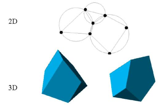
One of the key points for the success of the Lagrangian flow formulation described here is the fast regeneration of a mesh at every time step on the basis of the position of the nodes in the space domain. In our work the mesh is generated using the so called extended Delaunay tesselation (EDT) presented in [Idelsohn et al. (2003a; 2003c; 2004)]. The EDT allows one to generate non standard meshes combining elements of arbitrary polyhedrical shapes (triangles, quadrilaterals and other polygons in 2D and tetrahedra, hexahedra and arbitrary polyhedra in 3D) in a computing time of order , where is the total number of nodes in the mesh (Figure 2). The continuous shape functions of the elements can be simply obtained using the so called meshless finite element interpolation (MFEM). Details of the mesh generation procedure and the derivation of the MFEM shape functions can be found in [Idelsohn et al. (2003a; 2003c; 2004)].
Once the new mesh has been generated the numerical solution is found at each time step using the fractional step algorithm described in the previous section.
|
| Figure 2: Generation of non standard meshes combining different polygons (in 2D) and polyhedra (in 3D) using the extended Delaunay technique. |
8 Identification of Boundary Surfaces
One of the main tasks in the PFEM is the correct definition of the boundary domain. Sometimes, boundary nodes are explicitly identified differently from internal nodes. In other cases, the total set of nodes is the only information available and the algorithm must recognize the boundary nodes.
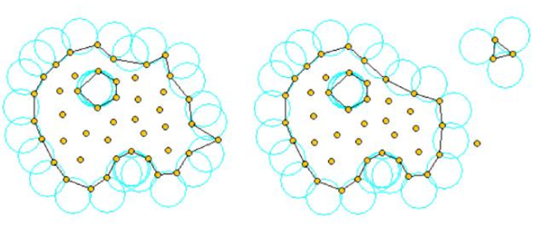
The extended Delaunay partition makes it easier to recognize boundary nodes. Considering that the nodes follow a variable distribution, where is typically the minimum distance between two nodes, the following criterion has been used. All nodes on an empty sphere with a radius greater than , are considered as boundary nodes. In practice is a parameter close to, but greater than one. This criterion is coincident with the Alpha Shape concept [Edelsbrunner and Mucke (1999)].
Figure 3 shows example of the boundary recognition using the Alpha Shape technique.
Once a decision has been made concerning which nodes are on the boundaries, the boundary surface is defined by all the polyhedral surfaces (or polygons in 2D) having all their nodes on the boundary and belonging to just one polyhedron.
The correct boundary surface is important to define the normal external to the surface. Furthermore, in weak forms (Galerkin) such as those used here a correct evaluation of the volume domain is also important. In the criterion proposed above, the error in the boundary surface definition is proportional to which is an acceptable error.
The method described also allows one to identify isolated fluid particles outside the main fluid domain. These particles are treated as part of the external boundary where the pressure is fixed to the atmospheric value (Figure 3) .
A practical application of the method for identifying free surface particles is shown in Figure 4. The example corresponds to the analysis of the motion of a fluid within an oscillating ellipsoidal container.
|
| Figure 3: Identification of individual particles (or a group of particles) starting from a given collection of nodes. |

|
| Figure 4: Motion of a liquid within an oscillating container. Position of the liquid particles at two different times. |

|
| Figure 5: 2D simulation of the penetration and evolution of a cube and a cylinder in a water container. The colours denote the different sizes of the elements at several times. |
9 Examples
The examples chosen show the applicability of the PFEM to solve problems involving large fluid motions and FSI situations.
9.1 Rigid objects filling into water
The analysis of the motion of submerged or floating objects in water is of great interest in many areas of harbour and coastal engineering and naval architecture among others.
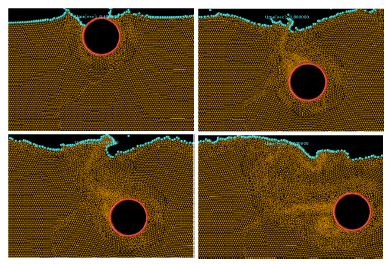
Figure 5 shows the penetration and evolution of a cube and a cylinder in a container with water. The colours denote the different sizes of the elements at several times. Figure 6 shows that the mesh generation algorithm ensures a smaller size of elements in the vicinity of the moving bodies during their motion.
|
| Figure 6: Detail of element sizes during the motion of a rigid cylinder within a water container. |
| Propagation of a wave generated in a test canal impacting with a vertical wall. |
| Figure 7: Propagation of a wave generated in a test canal impacting with a vertical wall. |
9.2 Impact of water streams on rigid structures
Figure 7 shows the simulation of the propagation of a wave generated in a test canal impacting on a vertical wall. Figure 8 shows a comparison of the experimental and numerical values of the water pressure on the vertical wall. The overall agreement is noticeable.
Figure 9 shows an example of a wave breaking within a prismatic container including a vertical cylinder. Finally Figure 10 shows the impact of a wave on a vertical column sustained by four pillars. The objective of this example was to model the impact of a water stream on a bridge pier accounting for the foundation effects.
| Comparison of experimental and numerical water pressures at the vertical wall for the example of Figure 7. |
| Figure 8: Comparison of experimental and numerical water pressures at the vertical wall for the example of Figure 7. |
| File:Draft Samper 662632188-diap9.png | Evolution of a water column within a prismatic container including a vertical cylinder. |
| Figure 9: Evolution of a water column within a prismatic container including a vertical cylinder. | |
| Impact of a wave on a prismatic column on a slab sustained by four pillars. |
| Figure 10: Impact of a wave on a prismatic column on a slab sustained by four pillars. |
9.3 Dragging of objects by water streams
Figure 11 shows the effect of a wave impacting on a cube representing a vehicle. This situation is typical in flooding and Tsunami situations.
| Dragging of a cubic object by a water stream. |
| Figure 11: Dragging of a cubic object by a water stream. |
9.4 Impact of sea waves on breakwater and piers
Figure 12 shows the simulation of the impact of a wave generated in an experimental flume on a collection of water motion in the vicinity of the rocks represent a breakwater. Details of the water-rock interaction are shown in Figure 13.
Figure 14 shows a 3D analysis of a similar problem. Figure 15 shows the 3D simulation of the interaction of a wave with a vertical pier formed by a collection of reinforced concrete cylinders.
The last examples shown in Figures 16 and 17 evidence the potential of the PFEM to solve 3D problems involving complex interactions between water and solid objects. Figure 16 shows the simulation of the falling of two tetrapods in a water container. Finally, Figure 17 shows the motion of a collection of ten tetrapods placed in a slope under an incident wave.
| Generation and impact of a wave on a collection of rocks in a breakwater. |
| Figure 12: Generation and impact of a wave on a collection of rocks in a breakwater. |
| Detail of the impact of a wave on a breakwater. The arrows indicate the water force on the rocks at different instants. |
| Figure 13: Detail of the impact of a wave on a breakwater. The arrows indicate the water force on the rocks at different instants. |
| 3D simulation of the impact of a wave on a collection of rocks in a breakwater. |
| Figure 14: 3D simulation of the impact of a wave on a collection of rocks in a breakwater. |
| Interaction of a wave with a vertical pier formed by reinforced concrete cylinders. |
| Figure 15: Interaction of a wave with a vertical pier formed by reinforced concrete cylinders. |
| Motion of two tetrapods falling in a water container. |
| Figure 16: Motion of two tetrapods falling in a water container. |
10 Conclusions
The particle finite element method (PFEM) is ideal to treat problems involving fluids with free surface and submerged or floating structures within a unified Lagrangian finite element framework. Problems such as the analysis of fluid-structure interaction, large motion of fluid or solid particles, surface waves, water splashing, separation of water drops, etc. can be easily solved with the PFEM. The success of the method lies in the accurate and efficient solution of the equations of an incompressible fluid and of solid dynamics using a stabilized finite element method allowing the use of low order elements with equal order interpolation for all the variables. Other essential solution ingredients are the efficient regeneration of the finite element mesh using an extended Delaunay tesselation, the meshless finite element interpolation (MFEM) and the identification of the boundary nodes using an Alpha Shape type technique. The examples presented have shown the potential of the PFEM for solving a wide class of practical FSI problems.
| File:Draft Samper 662632188-diap25.png | Motion of ten tetrapods on a slope under an incident wave. |
| Figure 17: Motion of ten tetrapods on a slope under an incident wave. | |
Acknowledgements
Thanks are given to Dr. F. Del Pin, Dr. N. Calvo and Ms. M. de Mier for many useful suggestions.
References
[1] Aubry R, Idelsohn SR, Oñate E (2005) Particle finite element method in fluid mechanics including thermal convection-diffusion. Computer & Structures 83(17-18):1459–1475
[2] Codina R, Zienkiewicz OC (2002) CBS versus GLS stabilization of the incompressible Navier-Stokes equations and the role of the time step as stabilization parameter. Communications in Numerical Methods in Engineering 18(2):99–112
[3] Donea J, Huerta A (2003) Finite element method for flow problems. J. Wiley.
[4] Edelsbrunner H, Mucke EP (1999) Three dimensional alpha shapes. ACM Trans. Graphics 13:43–72
[5] García J, Oñate E (2003) An unstructured finite element solver for ship hydrodynamic problems. J. Appl. Mech. 70:18–26 January
[6] Idelsohn SR, Oñate E, Del Pin F, Calvo N (2002) Lagrangian formulation: the only way to solve some free-surface fluid mechanics problems. Fith World Congress on Computational Mechanics, Mang HA, Rammerstorfer FG, Eberhardsteiner J (eds), July 7–12, Viena, Austria
[7] Idelsohn SR, Oñate E, Calvo N, Del Pin F (2003a) The meshless finite element method. Int. J. Num. Meth. Engng. 58(6):893–912
[8] Idelsohn SR, Oñate E, Del Pin F (2003b) A lagrangian meshless finite element method applied to fluid-structure interaction problems. Computer and Structures 81:655–671
[9] Idelsohn SR, Calvo N, Oñate E (2003c) Polyhedrization of an arbitrary point set. Comput. Method Appl. Mech. Engng. 192(22-24):2649–2668
[10] Idelsohn SR, Oñate E, Del Pin F (2004) The particle finite element method: a powerful tool to solve incompressible flows with free-surfaces and breaking waves. Int. J. Num. Meth. Engng. 61:964-989
[11] Oñate E (1998) Derivation of stabilized equations for advective-diffusive transport and fluid flow problems. Comput. Meth. Appl. Mech. Engng. 151:233–267
[12] Oñate E, (2000) A stabilized finite element method for incompressible viscous flows using a finite increment calculus formulation. Comp. Meth. Appl. Mech. Engng. 182(1–2):355–370
[13] Oñate E (2004) Possibilities of finite calculus in computational mechanics. Int. J. Num. Meth. Engng. 60(1):255–281
[14] Oñate E, Idelsohn SR (1998) A mesh free finite point method for advective-diffusive transport and fluid flow problems. Computational Mechanics 21:283–292
[15] Oñate E, García J (2001) A finite element method for fluid-structure interaction with surface waves using a finite calculus formulation. Comput. Meth. Appl. Mech. Engrg. 191:635–660
[16] Oñate E, Sacco C, Idelsohn SR (2000) A finite point method for incompressible flow problems. Comput. Visual. in Science 2:67–75
[17] Oñate E, Idelsohn SR, Del Pin F (2003) Lagrangian formulation for incompressible fluids using finite calculus and the finite element method. Numerical Methods for Scientific Computing Variational Problems and Applications, Y Kuznetsov, P Neittanmaki, O Pironneau (Eds.), CIMNE, Barcelona
[18] Oñate E, García J, Idelsohn SR (2004a) Ship hydrodynamics. Encyclopedia of Computational Mechanics, E Stein, R de Borst, T.J.R. Hughes (Eds), J. Wiley.
[19] Oñate E, Idelsohn SR, Del Pin F, Aubry R (2004b) The particle finite element method. An overview. Int. J. Comput. Methods 1(2):267-307
[20] Zienkiewicz OC, Taylor RL, Nithiarasu P (2006) The finite element method for fluid dynamics, Elsevier
[21] Zienkiewicz OC, Taylor RL (2005) The finite element method for solid and structural mechanics. Elsevier
