| (40 intermediate revisions by 3 users not shown) | |||
| Line 17: | Line 17: | ||
[mailto:murali@sonatech.ac.in '''murali@sonatech.ac.in''']''', '''[mailto:arulmozhiyal@sonatech.ac.in '''arulmozhiyal@sonatech.ac.in''']''' '''</div> | [mailto:murali@sonatech.ac.in '''murali@sonatech.ac.in''']''', '''[mailto:arulmozhiyal@sonatech.ac.in '''arulmozhiyal@sonatech.ac.in''']''' '''</div> | ||
--> | --> | ||
| − | |||
==Abstract== | ==Abstract== | ||
This paper deals with mathematical modeling of Permanent magnet brushless DC (BLDC) motor in MATLAB-SIMULINK environment. | This paper deals with mathematical modeling of Permanent magnet brushless DC (BLDC) motor in MATLAB-SIMULINK environment. | ||
| − | + | Modeling of BLDC motor carried in transfer function, transfer equations and state space model to verify the performance as actuators. Mathematical switches to control electronic commutation of BLDC motor based on signals of Hall Effect position sensor using three-phase inverter drive. Performance of the simplified mathematical inverter fed BLDC motor under steady state and dynamic conditions analyzed. Due to the switching losses during PWM generation generates low ripple content in torque of BLDC motor which described and eliminated through state space model. Comparison made of proposed modeling of BLDC motor with motor parameters like back-EMF, stator current and speed of BLDC motor, proposed work suggests the state space modeling holds a superior method for design of BLDC motor during high dynamic load performance and operating ranges. | |
| − | + | '''Keywords''': BLDC motor, transfer equation, MATLAB, simulink, transfer function, state space model | |
| − | =1 Introduction= | + | ==1. Introduction== |
| − | BRUSHLESS dc motor recommended high and low power applications due to their advantages of high-efficiency, high torque/inertia ratio, variable speed operation, and low electromagnetic interference[1]. A BLDC motor is silent operation, compact form, high torque-speed characteristics reliability and low maintenance [2-3]. Stator with three-phase winding arranged in trapezoidal nature excited with permanent magnets on the rotor. BLDC motor adds advantage of brush-less in commutator arrangement and an electronic based commutation of hall based position sensors used as a feedback signals [4-5]. the limitations met in BLDC motor due for variable speed operation over last decades continuing technology development in power semiconductors, microprocessors, adjustable speed drivers control schemes and permanent-magnet brushless electric motor production joined to enable reliable, cost-effective solution for a broad range of adjustable speed applications[6-8]. However, modelling of BLDC is a challenge to any users due its stator winding in trapezoidal nature and rotor magnets position needs to be sensed at every instant to operate particular switches in ON and OFF condition [9-12]. A Hall Effect sensor is used to provide rotor magnets information and corresponding decoding signals to ON –OFF PWM signals. It is necessary to model actuator with effective dynamic performance system and less ripple harmonics [13-16]. | + | BRUSHLESS dc motor recommended high and low power applications due to their advantages of high-efficiency, high torque/inertia ratio, variable speed operation, and low electromagnetic interference [1]. A BLDC motor is silent operation, compact form, high torque-speed characteristics reliability and low maintenance [2-3]. Stator with three-phase winding arranged in trapezoidal nature excited with permanent magnets on the rotor. BLDC motor adds advantage of brush-less in commutator arrangement and an electronic based commutation of hall based position sensors used as a feedback signals [4-5]. the limitations met in BLDC motor due for variable speed operation over last decades continuing technology development in power semiconductors, microprocessors, adjustable speed drivers control schemes and permanent-magnet brushless electric motor production joined to enable reliable, cost-effective solution for a broad range of adjustable speed applications [6-8]. However, modelling of BLDC is a challenge to any users due its stator winding in trapezoidal nature and rotor magnets position needs to be sensed at every instant to operate particular switches in ON and OFF condition [9-12]. A Hall Effect sensor is used to provide rotor magnets information and corresponding decoding signals to ON –OFF PWM signals. It is necessary to model actuator with effective dynamic performance system and less ripple harmonics [13-16]. |
The proposed BLDC motor modelling is carried in MATLAB simulink environment. MATLAB is an efficient tool for modelling an electrical systems and it is necessary to design BLDC motor i.e actuator for desire performance in overall systems [17-18]. Modelling of BLDC motor in MATLAB is proposed in this paper with three modelling methods state space model, state transfer equations and transfer functions. Modelling of BLDC motor is carried with three subsystems Modelling of Inverter, Modelling of Motor and Modelling of Decoder. | The proposed BLDC motor modelling is carried in MATLAB simulink environment. MATLAB is an efficient tool for modelling an electrical systems and it is necessary to design BLDC motor i.e actuator for desire performance in overall systems [17-18]. Modelling of BLDC motor in MATLAB is proposed in this paper with three modelling methods state space model, state transfer equations and transfer functions. Modelling of BLDC motor is carried with three subsystems Modelling of Inverter, Modelling of Motor and Modelling of Decoder. | ||
| − | + | ==2. Modelling of BLDC motor== | |
| − | + | ||
| − | + | ||
| − | + | ||
| − | + | ||
| − | + | ||
| − | + | ||
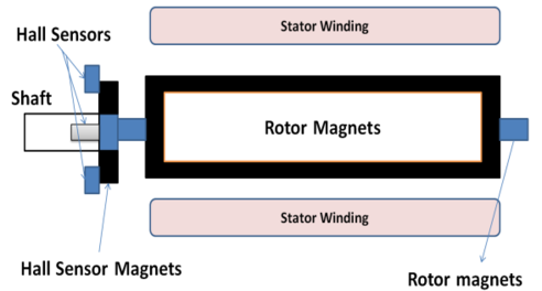
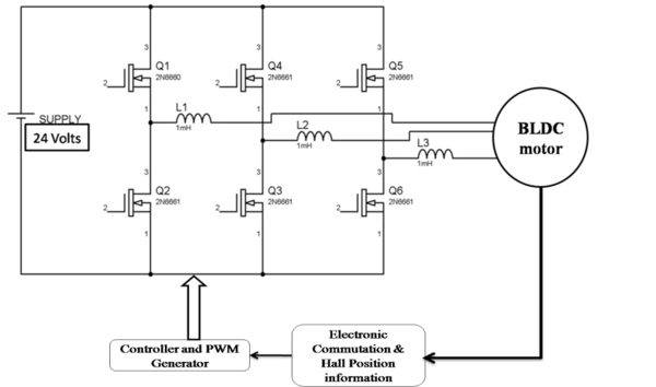
| − | Brushless DC motors modeling with three main parts: Stator, Rotor and Hall Sensor as shown in Figure | + | Brushless DC motors modeling with three main parts: Stator, Rotor and Hall Sensor as shown in [[#img-1|Figure 1]]. A three-phase BLDC motor has three stator phases that are excited two at a time to create a rotating electric field as represented in [[#img-2|Figure 2]]. The excitation on the stator must be sequenced in a specific manner while knowing the exact position of the rotor magnets [17] |
{| class="formulaSCP" style="width: 100%; text-align: center;" | {| class="formulaSCP" style="width: 100%; text-align: center;" | ||
| Line 47: | Line 40: | ||
{| style="text-align: center; margin:auto;" | {| style="text-align: center; margin:auto;" | ||
|- | |- | ||
| − | | <math | + | | <math>{v}_{ab}=R\left( {i}_{a}-{i}_{b}\right) +L\frac{d}{dt}\left( {i}_{a}-\right. </math><math>\left. {i}_{b}\right) +{e}_{a}-{e}_{b}</math> |
|} | |} | ||
| style="width: 5px;text-align: right;white-space: nowrap;" | (1) | | style="width: 5px;text-align: right;white-space: nowrap;" | (1) | ||
| Line 57: | Line 50: | ||
{| style="text-align: center; margin:auto;" | {| style="text-align: center; margin:auto;" | ||
|- | |- | ||
| − | | <math | + | | <math>{v}_{bc}=R\left( {i}_{b}-{i}_{c}\right) +L\frac{d}{dt}\left( {i}_{b}-\right. </math><math>\left. {i}_{c}\right) +{e}_{b}-{e}_{c}</math> |
|} | |} | ||
| style="width: 5px;text-align: right;white-space: nowrap;" | (2) | | style="width: 5px;text-align: right;white-space: nowrap;" | (2) | ||
| Line 67: | Line 60: | ||
{| style="text-align: center; margin:auto;" | {| style="text-align: center; margin:auto;" | ||
|- | |- | ||
| − | | <math | + | | <math>{v}_{ca}=R\left( {i}_{c}-{i}_{a}\right) +L\frac{d}{dt}\left( {i}_{c}-\right. </math><math>\left. {i}_{a}\right) +{e}_{c}-{e}_{a}</math> |
|} | |} | ||
| style="width: 5px;text-align: right;white-space: nowrap;" | (3) | | style="width: 5px;text-align: right;white-space: nowrap;" | (3) | ||
|} | |} | ||
| + | where <math>{v}_{ab}</math>, <math>{v}_{bc}</math> and <math>{v}_{ca}</math> are the stator phase voltages, <math>R</math> is the stator resistance per phase, <math>{i}_{a}</math>, <math>{i}_{b}</math> and <math>{i}_{c}</math> are the stator phase currents <math>L</math> are inductance of phases. It has been assumed that resistance of all the winding are equal. It also has been assumed that if there no change in the rotor reluctance with angle because of a no salient rotor and then | ||
| + | |||
| + | <div id='img-1'></div> | ||
| + | {| style="text-align: center; border: 1px solid #BBB; margin: 1em auto; width: auto;max-width: auto;" | ||
| + | |- | ||
| + | |style="padding:10px;"| [[Image:Review_725138044962-image1-c.png|492px]] | ||
| + | |- style="text-align: center; font-size: 75%;" | ||
| + | | colspan="1" style="padding-bottom:10px;"| '''Figure 1'''. Structure of BLDC motor | ||
| + | |} | ||
| + | |||
| + | |||
| + | <div id='img-2'></div> | ||
| + | {| style="text-align: center; border: 1px solid #BBB; margin: 1em auto; width: auto;max-width: auto;" | ||
| + | |- | ||
| + | |style="padding:10px;"| [[Image:Review_725138044962-image2-c.png|600px]] | ||
| + | |- style="text-align: center; font-size: 75%;" | ||
| + | | colspan="1" style="padding-bottom:10px;"| '''Figure 2'''. Brushless DC motor drive system | ||
| + | |} | ||
| − | |||
BLDC motor model is electromagnetic torque and current of motor. The other is a mechanical part, which generates revolution of motor. Under the above assumption, the electrical part of BLDC motor can be represented as | BLDC motor model is electromagnetic torque and current of motor. The other is a mechanical part, which generates revolution of motor. Under the above assumption, the electrical part of BLDC motor can be represented as | ||
| Line 82: | Line 92: | ||
{| style="text-align: center; margin:auto;" | {| style="text-align: center; margin:auto;" | ||
|- | |- | ||
| − | | <math | + | | <math>{e}_{a}=\frac{{k}_{e}}{2}{\omega }_{m}F{\theta }_{e}</math> |
|} | |} | ||
| style="width: 5px;text-align: right;white-space: nowrap;" | (4) | | style="width: 5px;text-align: right;white-space: nowrap;" | (4) | ||
|} | |} | ||
| + | {| class="formulaSCP" style="width: 100%; text-align: center;" | ||
| + | |- | ||
| + | | | ||
| + | {| style="text-align: center; margin:auto;" | ||
| + | |- | ||
| + | | <math>e_{b}=\frac{{k}_{e}}{2}{\omega }_{m}F({\theta }_{e}-\frac{2\pi }{3}</math> | ||
| + | |} | ||
| + | | style="width: 5px;text-align: right;white-space: nowrap;" | (5) | ||
| + | |} | ||
| − | + | {| class="formulaSCP" style="width: 100%; text-align: center;" | |
| − | + | |- | |
| − | <math | + | | |
| + | {| style="text-align: center; margin:auto;" | ||
| + | |- | ||
| + | | <math>{e}_{c}=\frac{{k}_{e}}{2}{\omega }_{m}F({\theta }_{e}-\frac{4\pi }{3}</math> | ||
| + | |} | ||
| + | | style="width: 5px;text-align: right;white-space: nowrap;" | (6) | ||
| + | |} | ||
The stator phase currents are constrained to be balanced | The stator phase currents are constrained to be balanced | ||
| − | + | {| class="formulaSCP" style="width: 100%; text-align: center;" | |
| + | |- | ||
| + | | | ||
| + | {| style="text-align: center; margin:auto;" | ||
| + | |- | ||
| + | | <math>I_{a} +I_b + I_c =0</math> | ||
| + | |} | ||
| + | | style="width: 5px;text-align: right;white-space: nowrap;" | (7) | ||
| + | |} | ||
{| class="formulaSCP" style="width: 100%; text-align: center;" | {| class="formulaSCP" style="width: 100%; text-align: center;" | ||
| Line 101: | Line 134: | ||
{| style="text-align: center; margin:auto;" | {| style="text-align: center; margin:auto;" | ||
|- | |- | ||
| − | | <math | + | | <math>{T}_{e}=\frac{{k}_{t}}{2}\left[ F\left( {\theta }_{e}\right) {i}_{a}+ F({\theta }_{e}-\frac{2\pi }{3}){i}_{b}+F({\theta }_{e}-\frac{4\pi }{3}){i}_{c}\right]</math> |
|} | |} | ||
| style="width: 5px;text-align: right;white-space: nowrap;" | (8) | | style="width: 5px;text-align: right;white-space: nowrap;" | (8) | ||
| Line 107: | Line 140: | ||
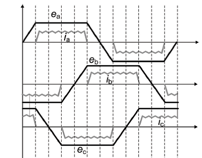
| − | The phase back EMF in the PMBLDC motor is trapezoidal in nature and is the function of the speed (9  | + | The phase back EMF in the PMBLDC motor is trapezoidal in nature and is the function of the speed (9 <math>\omega m</math> and rotor position angle <math>\theta</math>ras shown in [[#img-3|Figure 3]]. From this, the phase back EMF’S can be expressed as. |
| + | |||
{| class="formulaSCP" style="width: 100%; text-align: center;" | {| class="formulaSCP" style="width: 100%; text-align: center;" | ||
|- | |- | ||
| − | | <math>F\left( {\theta }_{e}\right) =\left\{ \begin{ | + | | |
| + | {| style="text-align: center; margin:auto;" | ||
| + | |- | ||
| + | | <math>F\left( {\theta }_{e}\right) =\left\{ | ||
| + | \begin{array}{cl} | ||
| + | \displaystyle 1,\quad \quad & \displaystyle 0\leq {\theta }_{e}\leq \frac{2\pi }{3}\\ | ||
| + | \displaystyle 1-\frac{6}{\pi }\left( {\theta }_{e}-\frac{2\pi }{3}\right) \frac{2\pi }{3}\leq {\theta }_{e}<\, \pi & \\ | ||
| + | \displaystyle -1\quad \quad & \displaystyle \pi \leq {\theta }_{e}<\frac{5\pi }{3}\\ | ||
| + | \displaystyle -1+\frac{6}{\pi }\frac{5\pi }{3}\leq {\theta }_{e}<\, 2\pi & \end{array}\right.</math> | ||
| + | |} | ||
| + | | style="width: 5px;text-align: right;white-space: nowrap;" | (9) | ||
|} | |} | ||
| Line 118: | Line 162: | ||
{| style="text-align: center; margin:auto;" | {| style="text-align: center; margin:auto;" | ||
|- | |- | ||
| − | | <math | + | | <math>{T}_{e}=\, {k}_{f}{\omega }_{m}+\, J\frac{d{\omega }_{m}}{dt}+{T}_{L}</math> |
|} | |} | ||
| style="width: 5px;text-align: right;white-space: nowrap;" | (10) | | style="width: 5px;text-align: right;white-space: nowrap;" | (10) | ||
|} | |} | ||
| + | <div id='img-1'></div> | ||
| + | {| style="text-align: center; border: 1px solid #BBB; margin: 1em auto; width: auto;max-width: auto;" | ||
| + | |- | ||
| + | |style="padding:10px;"| [[Image:Review_725138044962-image3.png|492px]] | ||
| + | |- style="text-align: center; font-size: 75%;" | ||
| + | | colspan="1" style="padding-bottom:10px;"| '''Figure 3'''. Trapezoidal back EMF of three phase BLDC motor | ||
| + | |} | ||
| − | + | ==3. PWM current controller== | |
| − | + | ||
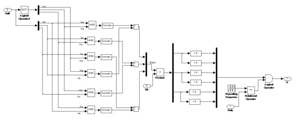
| − | + | PWM Current Controller generation is dependable to generate three phase reference currents, to generate PWM Current Controller block to compare reference current and observed current. Current error generates fed to build up required PWM signals for switching power electronics switches to drive BLDC motor as shown in [[#img-4|Figure 4]] a MATLAB-SIMULINK model. | |
| − | Figure. | + | |
| − | <div | + | <div id='img-4'></div> |
| − | [[Image:Review_725138044962- | + | {| style="text-align: center; border: 1px solid #BBB; margin: 1em auto; width: auto;max-width: auto;" |
| + | |- | ||
| + | |style="padding:10px;"| [[Image:Review_725138044962-image4-c.png|600px]] | ||
| + | |- style="text-align: center; font-size: 75%;" | ||
| + | | colspan="1" style="padding-bottom:10px;"| '''Figure 4'''. PWM current controller | ||
| + | |} | ||
| − | + | ==4. Modelling of BLDC motor== | |
| − | + | ||
| − | = | + | ===4.1 Modelling of BLDC motor in transfer function=== |
| − | + | BLDC motor parameter equation is derived in a transfer function block in a behavior to deliver desired current, back-EMF speed and torque motor characteristics. The complete MATLAB model is modeled in [[#img-5|Figure 5]] with the load torque is tested for different load applying conditions to verify the proposed modeling procedure is suitable as a motor. Back-EMF generation for three phases is simulated using corresponding theta and gamma values manipulated from motor position information as represents in [[#img-6|Figure 6]]. | |
| − | <div | + | <div id='img-5'></div> |
| − | [[Image:Review_725138044962- | + | {| style="text-align: center; border: 1px solid #BBB; margin: 1em auto; width: auto;max-width: auto;" |
| − | + | |- | |
| + | |style="padding:10px;"| [[Image:Review_725138044962-image5.png|600px]] | ||
| + | |- style="text-align: center; font-size: 75%;" | ||
| + | | colspan="1" style="padding-bottom:10px;"| '''Figure 5'''. BLDC motor modeling in transfer function | ||
| + | |} | ||
| − | |||
| − | |||
| − | = | + | <div id='img-6'></div> |
| + | {| style="text-align: center; border: 1px solid #BBB; margin: 1em auto; width: auto;" | ||
| + | |- | ||
| + | |style="padding-top:10px;"| [[File:Murali_Arulmozhiyal_2020a_1351_432px-Review_725138044962-image6-c.png|532px]] | ||
| + | <!--style="padding:10px;"| [[Image:Review_725138044962-image6-c.png|432px]]--> | ||
| + | |- | ||
| + | |[[File:Murali_Arulmozhiyal_2020a_2301_492px-Review_725138044962-image7-c.png|592px]] | ||
| + | |- style="text-align: center; font-size: 75%;" | ||
| + | | colspan="1" style="padding-bottom:10px;"| '''Figure 6'''. Back EMF Generation Of SIMULINK Blocks | ||
| + | |} | ||
| − | ==4. | + | ===4.2 Modelling of BLDC motor in transfer equation=== |
| − | BLDC motor | + | BLDC motor is modeled using transfer equations with voltage and current equations with inverter and gate decoder circuits. Motor model is based on input parameters of Van,Vbn,Vcn and load torque(Tl) as shown in equations(1-3,8) to generate voltage with corresponding back-EMF (Ea, Eb,Ec). To generate angle back-EMF a look up based logic is used with motor back-EMF constant (Ke) as described. Total electromagnetic torque is become conversant with by summing electrical and mechanical torque with product of torque constant (Kl). The mechanical side motor modeling is carried in a transfer equations based modeling as parameter rotor inertia, static and rotor dynamic torque constant. The complete modeling of BLDC motor with inverter gate drive and back-EMF generations in transfer equations is shown in [[#img-7|Figure 7]] to form transfer function and modeled using MATLAB-SIMULINK [19]. |
| − | <div | + | <div id='img-1'></div> |
| − | [[ | + | {| style="text-align: center; border: 1px solid #BBB; margin: 1em auto; width: auto;" |
| + | |- | ||
| + | |style="padding:10px;"| [[File:Murali_Arulmozhiyal_2020a_8303_528px-Review_725138044962-image8-c.png]] | ||
| + | |- style="text-align: center; font-size: 75%;" | ||
| + | | colspan="1" style="padding-bottom:10px;"| '''Figure 7'''. Modeling Of BLDC motor in transfer equations | ||
| + | |} | ||
| − | + | ===4.3 Modelling of BLDC motor in State space modelling === | |
| − | + | ||
| + | BLDC motor equations is modeled in state space form and fed through a state space block sets MATLAB simulink model as in [[#img-8|Figure 8]] with corresponding input voltage variables and output variables as velocity, theta angle and current. The state space model equations variables model is implemented, by considering: the stator phase resistances and inductance described as per data sheets faulhaber motor. In modeling of inverter a mathematical switches is considered neglecting the hysteresis and eddy current losses. | ||
| − | <div | + | <div id='img-8'></div> |
| − | + | {| style="text-align: center; border: 1px solid #BBB; margin: 1em auto; width: auto;max-width: auto;" | |
| − | + | |- | |
| − | Figure. | + | |style="padding:10px;"| [[Image:Review_725138044962-image9-c.png|600px]] |
| + | |- style="text-align: center; font-size: 75%;" | ||
| + | | colspan="1" style="padding-bottom:10px;"| '''Figure 8'''. Modeling of BLDC motor in state space | ||
| + | |} | ||
| − | ==4. | + | ===4.4 Simulation results and discussions=== |
| − | BLDC motor is | + | The design of BLDC motor is verified using parameters listed in [[#tab-1|Table 1]] and modeled in MATLAB SIMULINK environment to verify design analysis of Brushless DC motor. A Faulhaber BLDC[18] motor (Series-2444024B) and Motor driver rated current 6A peak have been taken for simulation with BLDC motor is set value of 10000rpm speed and simulated performance of motor at no load and loaded condition is presented. |
| − | <div class="center" style=" | + | <div class="center" style="font-size: 75%;"> |
| − | + | '''Table 1'''. BLDC motor parameters</div> | |
| − | <div | + | <div id='tab-1'></div> |
| − | + | {| class="wikitable" style="margin: 1em auto 0.1em auto;border-collapse: collapse;font-size:85%;width:auto;" | |
| − | + | |-style="text-align:center" | |
| − | + | ! Motor parameter !! Symbol !! Values !! Units | |
| − | + | ||
| − | + | ||
| − | + | ||
| − | + | ||
| − | + | ||
| − | + | ||
| − | + | ||
| − | + | ||
| − | + | ||
| − | + | ||
| − | + | ||
| − | + | ||
| − | + | ||
| − | + | ||
| − | + | ||
| − | + | ||
| − | + | ||
|- | |- | ||
| − | | style=" | + | | style="text-align: center;vertical-align: center;"|Nominal Voltage |
| − | | style=" | + | | style="text-align: center;vertical-align: center;"|Vn |
| − | | style=" | + | | style="vertical-align: center;"|24 |
| − | | style=" | + | | style="text-align: center;vertical-align: center;"|Volt |
|- | |- | ||
| − | | style=" | + | | style="text-align: center;vertical-align: center;"|Terminal resistance |
| − | | style=" | + | | style="text-align: center;vertical-align: center;"|R |
| − | | style=" | + | | style="vertical-align: center;"|1.16 |
| − | | style=" | + | | style="text-align: center;vertical-align: center;"|Ohms |
|- | |- | ||
| − | | style=" | + | | style="text-align: center;vertical-align: center;"|Output power |
| − | | style=" | + | | style="text-align: center;vertical-align: center;"|<math>P_{2\max}</math> |
| − | | style=" | + | | style="vertical-align: center;"|101 |
| − | | style=" | + | | style="text-align: center;vertical-align: center;"|Watts |
|- | |- | ||
| − | | style=" | + | | style="text-align: center;vertical-align: center;"|Speed constant |
| − | | style=" | + | | style="text-align: center;vertical-align: center;"|Kn |
| − | | style=" | + | | style="vertical-align: center;"|475 |
| − | | style=" | + | | style="text-align: center;vertical-align: center;"|Rpm/V |
|- | |- | ||
| − | | style=" | + | | style="text-align: center;vertical-align: center;"|Current constant |
| − | + | | style="text-align: center;vertical-align: center;"|Ki | |
| − | + | | style="vertical-align: center;"|0.050 | |
| − | + | | style="text-align: center;vertical-align: center;"|A/mNm | |
| − | + | ||
| − | + | ||
| − | | style=" | + | |
| − | | style=" | + | |
| − | | style=" | + | |
|} | |} | ||
| − | + | Faulhaber BLDC Motor with model 3564B series is designed in MATLAB based on transfer function, state space modeling as shown in [[#img-9|Figure 9]] and transfer equations in open-loop condition and results is presented in [[#img-10|Figure 10]]. The Motor characteristic of each modeling method is tabulated below in [[#tab-2|Table 2]]. | |
| − | [[ | + | |
| − | <div | + | <div id='img-9'></div> |
| − | Figure | + | {| style="text-align: center; border: 1px solid #BBB; margin: 1em auto; width: auto;max-width: auto;" |
| + | |- | ||
| + | |style="padding:10px;"| [[Image:Review_725138044962-image10-c.png|600px]] | ||
| + | |- style="text-align: center; font-size: 75%;" | ||
| + | | colspan="1" style="padding-bottom:10px;"| '''Figure 9'''. Output waveform of BLDC motor model in transfer functions | ||
| + | |} | ||
| − | |||
| − | |||
| − | <div | + | <div id='img-10'></div> |
| − | Figure | + | {| style="text-align: center; border: 1px solid #BBB; margin: 1em auto; width: auto;max-width: auto;" |
| + | |- | ||
| + | |style="padding:10px;"| [[Image:Review_725138044962-image11-c.png|516px]] | ||
| + | |- style="text-align: center; font-size: 75%;" | ||
| + | | colspan="1" style="padding-bottom:10px;"| '''Figure 10'''. Output waveforms of BLDC motor model in state space model | ||
| + | |} | ||
| − | |||
| − | |||
| − | |||
| − | {| style=" | + | <div class="center" style="font-size: 75%;">'''Table 2'''. BLDC Motor modelling comparison</div> |
| + | |||
| + | <div id='tab-1'></div> | ||
| + | {| class="wikitable" style="margin: 1em auto 0.1em auto;border-collapse: collapse;font-size:85%;width:auto;" | ||
| + | |-style="text-align:center" | ||
| + | ! style="text-align: left;"|Transfer Function !! Transfer equations !! State Space Modeling | ||
|- | |- | ||
| − | | style=" | + | | style="text-align: left;vertical-align: center;"|Speed (11300rpm) |
| − | | | + | | style="text-align: center;vertical-align: center;"|4000 range |
| − | | | + | | style="text-align: center;vertical-align: center;"|Achieved |
| − | | | + | | style="text-align: center;vertical-align: center;"|Achieved |
|- | |- | ||
| − | | | + | | style="text-align: left;vertical-align: center;"| Dynamic Characteristics (settling time to reach rated speed) |
| − | | style=" | + | | style="text-align: center;vertical-align: center;"|Slow |
| − | + | | style="text-align: center;vertical-align: center;"|Moderate | |
| − | + | | style="text-align: center;vertical-align: center;"|Fast | |
| − | + | ||
| − | | | + | |
| − | + | ||
| − | + | ||
| − | | | + | |
| − | | style=" | + | |
| − | + | ||
|- | |- | ||
| − | | | + | | style="text-align: left;vertical-align: center;"|Back EMF (Pure Trapezoidal) |
| − | | style=" | + | | style="text-align: center;vertical-align: center;"|Achieved |
| − | | style=" | + | | style="text-align: center;vertical-align: center;"|Achieved |
| − | | style=" | + | | style="text-align: center;vertical-align: center;"|Achieved |
|- | |- | ||
| − | | | + | | style="text-align: left;vertical-align: center;"|Current (quasi Square) |
| − | | | + | | style="text-align: center;vertical-align: center;"| N.A |
| − | | style=" | + | | style="text-align: center;vertical-align: center;"|N.A |
| − | | style=" | + | | style="text-align: center;vertical-align: center;"|Achieved |
|- | |- | ||
| − | | | + | | style="text-align: left;vertical-align: center;"|PWM Current control (IaIbIc) |
| − | | style=" | + | | style="text-align: center;vertical-align: center;"|N.A |
| − | | style=" | + | | style="text-align: center;vertical-align: center;"|Achieved |
| − | | style=" | + | | style="text-align: center;vertical-align: center;"|Achieved |
|- | |- | ||
| − | | | + | | style="text-align: left;vertical-align: center;"|Hysterias Current control (IaIbIc ) |
| − | | style=" | + | | style="text-align: center;vertical-align: center;"|Achieved |
| − | | style=" | + | | style="text-align: center;vertical-align: center;"|Achieved |
| − | | style=" | + | | style="text-align: center;vertical-align: center;"|Achieved |
|- | |- | ||
| − | | | + | | style="text-align: left;vertical-align: center;"|PWM Current control (Idc ) |
| − | | | + | | style="text-align: center;vertical-align: center;"| N.A |
| − | | style=" | + | | style="text-align: center;vertical-align: center;"|N.A |
| − | | style=" | + | | style="text-align: center;vertical-align: center;"|Achieved |
|- | |- | ||
| − | | style=" | + | | style="text-align: left;vertical-align: center;"|Hysterias current Controller(Idc ) |
| − | | style=" | + | | style="text-align: center;vertical-align: center;"|N.A |
| − | | style=" | + | | style="text-align: center;vertical-align: center;"|N.A |
| − | | style=" | + | | style="text-align: center;vertical-align: center;"|Achieved |
|} | |} | ||
| Line 296: | Line 348: | ||
From the results obtained from three modeling techniques of BLDC motor in Sim-power system has better performance compared with others. Powergui block in MATLAB has automatically converted the MATLAB-model into average model in SIMULINK which is not possible in transfer function and State-space modeling of BLDC motor. | From the results obtained from three modeling techniques of BLDC motor in Sim-power system has better performance compared with others. Powergui block in MATLAB has automatically converted the MATLAB-model into average model in SIMULINK which is not possible in transfer function and State-space modeling of BLDC motor. | ||
| − | =5 Conclusion= | + | ==5. Conclusion== |
The performance evaluation results show that, such a modelling is very useful in studying the drive system before taking up the dedicated controller design, accounting the relevant dynamic parameters of the motor. The paper presents an implementation of BLDC motor dynamic model, by using the transfer functions, transfer equations and state space modeling using MATLAB-SIMULINK in which all methods performed well and every method has its drawbacks. An inverter mathematical model is also simulated in MATLAB-SIMULINK with corresponding encoder, current controller and HALL sensor and back-EMF generation. Motor parameters of real BLDC motor is used and verified as per values in the data sheet. From the results obtained from three modeling techniques of BLDC motor, state space modeling worked well, it is efficient methods to model BLDC motor. By adopting BLDC motor modeling in state space form will be a potential advantage in many actuation system applications. | The performance evaluation results show that, such a modelling is very useful in studying the drive system before taking up the dedicated controller design, accounting the relevant dynamic parameters of the motor. The paper presents an implementation of BLDC motor dynamic model, by using the transfer functions, transfer equations and state space modeling using MATLAB-SIMULINK in which all methods performed well and every method has its drawbacks. An inverter mathematical model is also simulated in MATLAB-SIMULINK with corresponding encoder, current controller and HALL sensor and back-EMF generation. Motor parameters of real BLDC motor is used and verified as per values in the data sheet. From the results obtained from three modeling techniques of BLDC motor, state space modeling worked well, it is efficient methods to model BLDC motor. By adopting BLDC motor modeling in state space form will be a potential advantage in many actuation system applications. | ||
| − | =References= | + | ==References== |
| + | <div class="auto" style="text-align: left;width: auto; margin-left: auto; margin-right: auto;font-size: 85%;"> | ||
| − | [1] S. | + | [1] Chen S., Liu G., Zhu L. Sensorless startup strategy for a 315-kW high-speed brushless DC motor with small inductance and nonideal back EMF. In IEEE Transactions on Industrial Electronics, 66(3):1703-1714, 2019. |
| − | [2] B. V. R. Kumar | + | [2] Kumar B.V.R., Kumar K.S. Design of a new dual rotor radial flux BLDC motor with halbach array magnets for an electric vehicle. 2016 IEEE International Conference on Power Electronics, Drives and Energy Systems (PEDES), Trivandrum, pp. 1-5, 2016. |
| − | [3] R. | + | [3] Manikandan R., Arulmozhiyal R. Modeling and simulation of fuzzy based BLDC fed vertically rotating one DOF robot arm position control system. 2016 10th International Conference on Intelligent Systems and Control (ISCO), Coimbatore, pp. 1-7, 2016. |
| − | [4] R. | + | [4] Manikandan R., Arulmozhiyal R. Intelligent position control of a vertical rotating single arm robot using BLDC servo drive. Journal of Power Electronics, 16(1):205-216, 2016. |
| − | [5] Muniraj M. | + | [5] Muniraj M., Arulmozhiyal R. Modeling and simulation of control actuation system with fuzzy-PID logic controlled brushless motor drives for missiles glider applications. The Scientific World Journal, Hindawi Publishing Corporation, pp. 1-11, 2015. |
| − | [6] Arulmozhiyal R., Murali M. | + | [6] Arulmozhiyal R., Murali M., Manikanadan R. Modeling and simulation of control actuation system. ARPN Journal of Engineering and Applied Sciences, 10(4):1778-1782, 2015. |
| − | [7] J. | + | [7] Shao J. An improved microcontroller-based sensorless brushless DC (BLDC) motor drive for automotive applications. In IEEE Transactions on Industry Applications, 42(5):1216-1221, 2006. |
| − | [8] | + | [8] De Viaene J., Verbelen F., Derammelaere S., Stockman K. Energy-efficient sensorless load angle control of a BLDC motor using sinusoidal currents. In IET Electric Power Applications, 12(9):1378-1389, 2018. |
| − | [9] | + | [9] Yedamale P. Brushless DC (BLDC) motor fundamentals. Microchip Technology Inc., AN885, 2003. |
| − | [10] S. | + | [10] Baldursson S. BLDC motor modelling and control - A MATLAB/Simulink Implementation. Master Thesis, May 2005. |
| − | [11] B. | + | [11] Tibor B., Fedák V., Durovský F. Modeling and simulation of the BLDC motor in MATLAB GUI. 2011 IEEE International Symposium on Industrial Electronics, Gdansk, pp. 1403-1407, 2011. doi: 10.1109/ISIE.2011.5984365 |
| − | [12] Singh | + | [12] Singh C.P., Kulkarni S.S., Rana S.C., Deo K. State-space based simulink modeling of BLDC motor and its speed control using fuzzy PID controller. International Journal of Advances in Engineering Science and Technology, Vol. 2 , No. 3, 2013, pp. 359-369. |
| − | [13] Tashakori | + | [13] Tashakori A., Ektesabi M., Hosseinzadeh N. Modeling of BLDC motor with ideal back-EMF for automotive applications. In Proceedings of the World Congress on Engineering 2011, WCE 2011, London, U.K., July 6-8 2011. |
| − | [14] A. A. | + | [14] Laczko A.A., Zaharia M.V., Radulescu M.M., Brisset S. Modeling and simulation of a brushless DC permanent-magnet generator-based wind energy conversion system. 2015 Tenth International Conference on Ecological Vehicles and Renewable Energies (EVER), Monte Carlo, pp. 1-7, 31 March-2 April 2015. |
| − | [15] J. | + | [15] Gebauer J., Fojtík D., Podešva P. Modeling of the electronic variable pitch drive. Proceedings of the 2015 16th International Carpathian Control Conference (ICCC), Szilvasvarad, pp. 138-141, 27-30 May 2015. doi: 10.1109/CarpathianCC.2015.7145062. |
| − | [16] | + | [16] Faulhaber Miniature Drive Systems, www.faulhaber.com. |
| − | [17] Copeland | + | [17] Copeland B.R. The design of PID controllers using Ziegler Nichols tuning. March 2008. |
| − | [18] Pan S., Edelberg K. | + | [18] Pan S., Edelberg K., Hedrick J.K. Discrete adaptive sliding control of automotive powertrains. 2014 American Control Conference (ACC), Portland,Oregon, USA, 2014. |
| − | [19] Kumar S., Nigam M.J. | + | [19] Kumar S., Nigam M.J. Robust sliding mode control using fuzzy controller. Int. J. Sci. Res., 4(3):1470-1472, 2015. |
| + | </div> | ||
Latest revision as of 15:28, 20 May 2021
Abstract
This paper deals with mathematical modeling of Permanent magnet brushless DC (BLDC) motor in MATLAB-SIMULINK environment.
Modeling of BLDC motor carried in transfer function, transfer equations and state space model to verify the performance as actuators. Mathematical switches to control electronic commutation of BLDC motor based on signals of Hall Effect position sensor using three-phase inverter drive. Performance of the simplified mathematical inverter fed BLDC motor under steady state and dynamic conditions analyzed. Due to the switching losses during PWM generation generates low ripple content in torque of BLDC motor which described and eliminated through state space model. Comparison made of proposed modeling of BLDC motor with motor parameters like back-EMF, stator current and speed of BLDC motor, proposed work suggests the state space modeling holds a superior method for design of BLDC motor during high dynamic load performance and operating ranges.
Keywords: BLDC motor, transfer equation, MATLAB, simulink, transfer function, state space model
1. Introduction
BRUSHLESS dc motor recommended high and low power applications due to their advantages of high-efficiency, high torque/inertia ratio, variable speed operation, and low electromagnetic interference [1]. A BLDC motor is silent operation, compact form, high torque-speed characteristics reliability and low maintenance [2-3]. Stator with three-phase winding arranged in trapezoidal nature excited with permanent magnets on the rotor. BLDC motor adds advantage of brush-less in commutator arrangement and an electronic based commutation of hall based position sensors used as a feedback signals [4-5]. the limitations met in BLDC motor due for variable speed operation over last decades continuing technology development in power semiconductors, microprocessors, adjustable speed drivers control schemes and permanent-magnet brushless electric motor production joined to enable reliable, cost-effective solution for a broad range of adjustable speed applications [6-8]. However, modelling of BLDC is a challenge to any users due its stator winding in trapezoidal nature and rotor magnets position needs to be sensed at every instant to operate particular switches in ON and OFF condition [9-12]. A Hall Effect sensor is used to provide rotor magnets information and corresponding decoding signals to ON –OFF PWM signals. It is necessary to model actuator with effective dynamic performance system and less ripple harmonics [13-16].
The proposed BLDC motor modelling is carried in MATLAB simulink environment. MATLAB is an efficient tool for modelling an electrical systems and it is necessary to design BLDC motor i.e actuator for desire performance in overall systems [17-18]. Modelling of BLDC motor in MATLAB is proposed in this paper with three modelling methods state space model, state transfer equations and transfer functions. Modelling of BLDC motor is carried with three subsystems Modelling of Inverter, Modelling of Motor and Modelling of Decoder.
2. Modelling of BLDC motor
Brushless DC motors modeling with three main parts: Stator, Rotor and Hall Sensor as shown in Figure 1. A three-phase BLDC motor has three stator phases that are excited two at a time to create a rotating electric field as represented in Figure 2. The excitation on the stator must be sequenced in a specific manner while knowing the exact position of the rotor magnets [17]
|
|
(1) |
|
|
(2) |
|
|
(3) |
where , and are the stator phase voltages, is the stator resistance per phase, , and are the stator phase currents are inductance of phases. It has been assumed that resistance of all the winding are equal. It also has been assumed that if there no change in the rotor reluctance with angle because of a no salient rotor and then
|
| Figure 1. Structure of BLDC motor |
|
| Figure 2. Brushless DC motor drive system |
BLDC motor model is electromagnetic torque and current of motor. The other is a mechanical part, which generates revolution of motor. Under the above assumption, the electrical part of BLDC motor can be represented as
|
|
(4) |
|
|
(5) |
|
|
(6) |
The stator phase currents are constrained to be balanced
|
|
(7) |
|
|
(8) |
The phase back EMF in the PMBLDC motor is trapezoidal in nature and is the function of the speed (9 and rotor position angle ras shown in Figure 3. From this, the phase back EMF’S can be expressed as.
|
|
(9) |
|
|
(10) |
|
| Figure 3. Trapezoidal back EMF of three phase BLDC motor |
3. PWM current controller
PWM Current Controller generation is dependable to generate three phase reference currents, to generate PWM Current Controller block to compare reference current and observed current. Current error generates fed to build up required PWM signals for switching power electronics switches to drive BLDC motor as shown in Figure 4 a MATLAB-SIMULINK model.
|
| Figure 4. PWM current controller |
4. Modelling of BLDC motor
4.1 Modelling of BLDC motor in transfer function
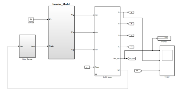
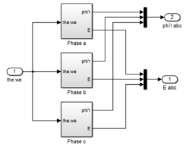
BLDC motor parameter equation is derived in a transfer function block in a behavior to deliver desired current, back-EMF speed and torque motor characteristics. The complete MATLAB model is modeled in Figure 5 with the load torque is tested for different load applying conditions to verify the proposed modeling procedure is suitable as a motor. Back-EMF generation for three phases is simulated using corresponding theta and gamma values manipulated from motor position information as represents in Figure 6.
|
| Figure 5. BLDC motor modeling in transfer function |
|

|
| Figure 6. Back EMF Generation Of SIMULINK Blocks |
4.2 Modelling of BLDC motor in transfer equation
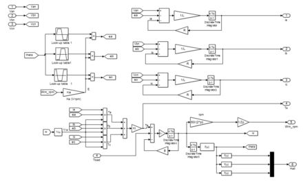
BLDC motor is modeled using transfer equations with voltage and current equations with inverter and gate decoder circuits. Motor model is based on input parameters of Van,Vbn,Vcn and load torque(Tl) as shown in equations(1-3,8) to generate voltage with corresponding back-EMF (Ea, Eb,Ec). To generate angle back-EMF a look up based logic is used with motor back-EMF constant (Ke) as described. Total electromagnetic torque is become conversant with by summing electrical and mechanical torque with product of torque constant (Kl). The mechanical side motor modeling is carried in a transfer equations based modeling as parameter rotor inertia, static and rotor dynamic torque constant. The complete modeling of BLDC motor with inverter gate drive and back-EMF generations in transfer equations is shown in Figure 7 to form transfer function and modeled using MATLAB-SIMULINK [19].
|
| Figure 7. Modeling Of BLDC motor in transfer equations |
4.3 Modelling of BLDC motor in State space modelling
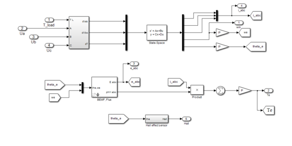
BLDC motor equations is modeled in state space form and fed through a state space block sets MATLAB simulink model as in Figure 8 with corresponding input voltage variables and output variables as velocity, theta angle and current. The state space model equations variables model is implemented, by considering: the stator phase resistances and inductance described as per data sheets faulhaber motor. In modeling of inverter a mathematical switches is considered neglecting the hysteresis and eddy current losses.
|
| Figure 8. Modeling of BLDC motor in state space |
4.4 Simulation results and discussions
The design of BLDC motor is verified using parameters listed in Table 1 and modeled in MATLAB SIMULINK environment to verify design analysis of Brushless DC motor. A Faulhaber BLDC[18] motor (Series-2444024B) and Motor driver rated current 6A peak have been taken for simulation with BLDC motor is set value of 10000rpm speed and simulated performance of motor at no load and loaded condition is presented.
| Motor parameter | Symbol | Values | Units |
|---|---|---|---|
| Nominal Voltage | Vn | 24 | Volt |
| Terminal resistance | R | 1.16 | Ohms |
| Output power | 101 | Watts | |
| Speed constant | Kn | 475 | Rpm/V |
| Current constant | Ki | 0.050 | A/mNm |
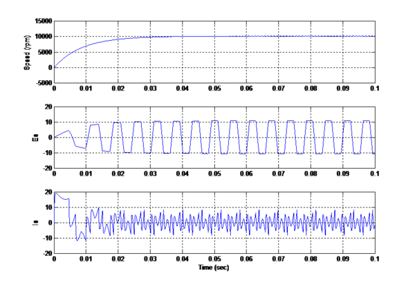
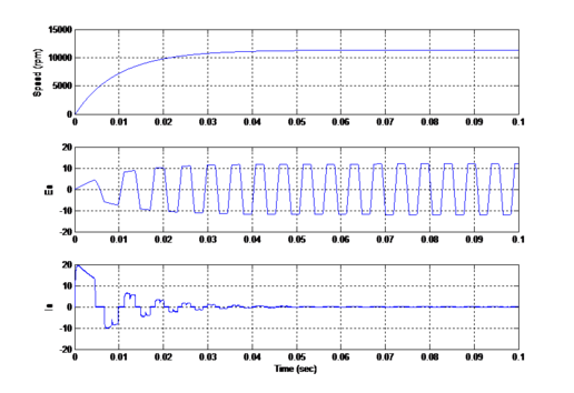
Faulhaber BLDC Motor with model 3564B series is designed in MATLAB based on transfer function, state space modeling as shown in Figure 9 and transfer equations in open-loop condition and results is presented in Figure 10. The Motor characteristic of each modeling method is tabulated below in Table 2.
|
| Figure 9. Output waveform of BLDC motor model in transfer functions |
|
| Figure 10. Output waveforms of BLDC motor model in state space model |
| Transfer Function | Transfer equations | State Space Modeling | |
|---|---|---|---|
| Speed (11300rpm) | 4000 range | Achieved | Achieved |
| Dynamic Characteristics (settling time to reach rated speed) | Slow | Moderate | Fast |
| Back EMF (Pure Trapezoidal) | Achieved | Achieved | Achieved |
| Current (quasi Square) | N.A | N.A | Achieved |
| PWM Current control (IaIbIc) | N.A | Achieved | Achieved |
| Hysterias Current control (IaIbIc ) | Achieved | Achieved | Achieved |
| PWM Current control (Idc ) | N.A | N.A | Achieved |
| Hysterias current Controller(Idc ) | N.A | N.A | Achieved |
From the results obtained from three modeling techniques of BLDC motor in Sim-power system has better performance compared with others. Powergui block in MATLAB has automatically converted the MATLAB-model into average model in SIMULINK which is not possible in transfer function and State-space modeling of BLDC motor.
5. Conclusion
The performance evaluation results show that, such a modelling is very useful in studying the drive system before taking up the dedicated controller design, accounting the relevant dynamic parameters of the motor. The paper presents an implementation of BLDC motor dynamic model, by using the transfer functions, transfer equations and state space modeling using MATLAB-SIMULINK in which all methods performed well and every method has its drawbacks. An inverter mathematical model is also simulated in MATLAB-SIMULINK with corresponding encoder, current controller and HALL sensor and back-EMF generation. Motor parameters of real BLDC motor is used and verified as per values in the data sheet. From the results obtained from three modeling techniques of BLDC motor, state space modeling worked well, it is efficient methods to model BLDC motor. By adopting BLDC motor modeling in state space form will be a potential advantage in many actuation system applications.
References
[1] Chen S., Liu G., Zhu L. Sensorless startup strategy for a 315-kW high-speed brushless DC motor with small inductance and nonideal back EMF. In IEEE Transactions on Industrial Electronics, 66(3):1703-1714, 2019.
[2] Kumar B.V.R., Kumar K.S. Design of a new dual rotor radial flux BLDC motor with halbach array magnets for an electric vehicle. 2016 IEEE International Conference on Power Electronics, Drives and Energy Systems (PEDES), Trivandrum, pp. 1-5, 2016.
[3] Manikandan R., Arulmozhiyal R. Modeling and simulation of fuzzy based BLDC fed vertically rotating one DOF robot arm position control system. 2016 10th International Conference on Intelligent Systems and Control (ISCO), Coimbatore, pp. 1-7, 2016.
[4] Manikandan R., Arulmozhiyal R. Intelligent position control of a vertical rotating single arm robot using BLDC servo drive. Journal of Power Electronics, 16(1):205-216, 2016.
[5] Muniraj M., Arulmozhiyal R. Modeling and simulation of control actuation system with fuzzy-PID logic controlled brushless motor drives for missiles glider applications. The Scientific World Journal, Hindawi Publishing Corporation, pp. 1-11, 2015.
[6] Arulmozhiyal R., Murali M., Manikanadan R. Modeling and simulation of control actuation system. ARPN Journal of Engineering and Applied Sciences, 10(4):1778-1782, 2015.
[7] Shao J. An improved microcontroller-based sensorless brushless DC (BLDC) motor drive for automotive applications. In IEEE Transactions on Industry Applications, 42(5):1216-1221, 2006.
[8] De Viaene J., Verbelen F., Derammelaere S., Stockman K. Energy-efficient sensorless load angle control of a BLDC motor using sinusoidal currents. In IET Electric Power Applications, 12(9):1378-1389, 2018.
[9] Yedamale P. Brushless DC (BLDC) motor fundamentals. Microchip Technology Inc., AN885, 2003.
[10] Baldursson S. BLDC motor modelling and control - A MATLAB/Simulink Implementation. Master Thesis, May 2005.
[11] Tibor B., Fedák V., Durovský F. Modeling and simulation of the BLDC motor in MATLAB GUI. 2011 IEEE International Symposium on Industrial Electronics, Gdansk, pp. 1403-1407, 2011. doi: 10.1109/ISIE.2011.5984365
[12] Singh C.P., Kulkarni S.S., Rana S.C., Deo K. State-space based simulink modeling of BLDC motor and its speed control using fuzzy PID controller. International Journal of Advances in Engineering Science and Technology, Vol. 2 , No. 3, 2013, pp. 359-369.
[13] Tashakori A., Ektesabi M., Hosseinzadeh N. Modeling of BLDC motor with ideal back-EMF for automotive applications. In Proceedings of the World Congress on Engineering 2011, WCE 2011, London, U.K., July 6-8 2011.
[14] Laczko A.A., Zaharia M.V., Radulescu M.M., Brisset S. Modeling and simulation of a brushless DC permanent-magnet generator-based wind energy conversion system. 2015 Tenth International Conference on Ecological Vehicles and Renewable Energies (EVER), Monte Carlo, pp. 1-7, 31 March-2 April 2015.
[15] Gebauer J., Fojtík D., Podešva P. Modeling of the electronic variable pitch drive. Proceedings of the 2015 16th International Carpathian Control Conference (ICCC), Szilvasvarad, pp. 138-141, 27-30 May 2015. doi: 10.1109/CarpathianCC.2015.7145062.
[16] Faulhaber Miniature Drive Systems, www.faulhaber.com.
[17] Copeland B.R. The design of PID controllers using Ziegler Nichols tuning. March 2008.
[18] Pan S., Edelberg K., Hedrick J.K. Discrete adaptive sliding control of automotive powertrains. 2014 American Control Conference (ACC), Portland,Oregon, USA, 2014.
[19] Kumar S., Nigam M.J. Robust sliding mode control using fuzzy controller. Int. J. Sci. Res., 4(3):1470-1472, 2015.
Document information
Published on 12/01/21
Accepted on 24/11/20
Submitted on 07/07/20
Volume 37, Issue 1, 2021
DOI: 10.23967/j.rimni.2020.12.001
Licence: CC BY-NC-SA license
Share this document
Keywords
claim authorship
Are you one of the authors of this document?