| (6 intermediate revisions by the same user not shown) | |||
| Line 24: | Line 24: | ||
In this paper, a second order SL-PFEM scheme for solving the incompressible Navier-Stokes equations is presented. This scheme is based on the second order velocity Verlet algorithm, which uses an explicit integration for the particle’s trajectory and an implicit integration for the velocity. The algorithm is completed with a predictor-multicorrector scheme for the integration of the velocity correction using the Finite Element Method. A second order projector based on least squares is used to transfer the intrinsic variables information from the particles onto the background mesh, while a second order interpolation scheme is used to transfer the accelerations from the mesh to the particles. Convergence analyses are carried out to assess the second order convergence. | In this paper, a second order SL-PFEM scheme for solving the incompressible Navier-Stokes equations is presented. This scheme is based on the second order velocity Verlet algorithm, which uses an explicit integration for the particle’s trajectory and an implicit integration for the velocity. The algorithm is completed with a predictor-multicorrector scheme for the integration of the velocity correction using the Finite Element Method. A second order projector based on least squares is used to transfer the intrinsic variables information from the particles onto the background mesh, while a second order interpolation scheme is used to transfer the accelerations from the mesh to the particles. Convergence analyses are carried out to assess the second order convergence. | ||
| + | |||
| + | The [https://link.springer.com/article/10.1007%2Fs40571-019-00258-9 final publication] is available at link.springer.com. | ||
<span id='_GoBack'></span>'''Keywords: '''Semi-Lagrangian, Particles, PFEM, FEM, Second-order | <span id='_GoBack'></span>'''Keywords: '''Semi-Lagrangian, Particles, PFEM, FEM, Second-order | ||
| Line 223: | Line 225: | ||
{| style="text-align: center; margin:auto;width: 100%;" | {| style="text-align: center; margin:auto;width: 100%;" | ||
|- | |- | ||
| − | | <math>\frac{{\mathit{\boldsymbol{U}}}_{\lambda }^{n+1}-{\mathit{\boldsymbol{U}}}_{\lambda }^{n}}{\Delta t}= | + | | <math>\frac{{\mathit{\boldsymbol{U}}}_{\lambda }^{n+1}-{\mathit{\boldsymbol{U}}}_{\lambda }^{n}}{\Delta t}=\frac{1}{2}\left( {\mathit{\boldsymbol{a}}}^{n}({\mathit{\boldsymbol{X}}}_{\lambda }^{n})+{\mathit{\boldsymbol{a}}}^{n+1}({\mathit{\boldsymbol{X}}}_{\lambda }^{n+1})\right)</math> |
|} | |} | ||
| style="width: 5px;text-align: right;white-space: nowrap;"|<span id='_Ref527451071'></span>(16) | | style="width: 5px;text-align: right;white-space: nowrap;"|<span id='_Ref527451071'></span>(16) | ||
| Line 236: | Line 238: | ||
{| style="text-align: center; margin:auto;width: 100%;" | {| style="text-align: center; margin:auto;width: 100%;" | ||
|- | |- | ||
| − | | <math>{\mathit{\boldsymbol{U}}}_{\lambda }^{n | + | | <math>{\mathit{\boldsymbol{U}}}_{\lambda }^{n+1}={\mathit{\boldsymbol{U}}}_{\lambda }^{n+1/2}+</math><math>\frac{\Delta t}{2}{\mathit{\boldsymbol{a}}}^{n+1}\left( {\mathit{\boldsymbol{X}}}_{\lambda }^{n+1}\right)</math> |
|} | |} | ||
| style="width: 5px;text-align: right;white-space: nowrap;"|<span id='_Ref3545805'></span><span id='_Ref527454686'></span>(17) | | style="width: 5px;text-align: right;white-space: nowrap;"|<span id='_Ref3545805'></span><span id='_Ref527454686'></span>(17) | ||
| Line 311: | Line 313: | ||
{| style="text-align: center; margin:auto;width: 100%;" | {| style="text-align: center; margin:auto;width: 100%;" | ||
|- | |- | ||
| − | | <math>{\hat{\mathit{\boldsymbol{u}}}}^{n+1,i+1}={\mathit{\boldsymbol{u}}}^{n+1/2}+\frac{\Delta t}{2}\left( - | + | | <math>{\hat{\mathit{\boldsymbol{u}}}}^{n+1,i+1}={\mathit{\boldsymbol{u}}}^{n+1/2}+\frac{\Delta t}{2}\left(-\nabla \left( \frac{{P}^{n+1,i}}{\rho }\right) +\nu \Delta {\hat{\mathit{\boldsymbol{u}}}}^{n+1,i+1}+{\mathit{\boldsymbol{f}}}^{n+1}\right)</math> |
|} | |} | ||
| style="width: 5px;text-align: right;white-space: nowrap;"|<span id='_Ref527460900'></span>(22) | | style="width: 5px;text-align: right;white-space: nowrap;"|<span id='_Ref527460900'></span>(22) | ||
| Line 318: | Line 320: | ||
{| style="text-align: center; margin:auto;width: 100%;" | {| style="text-align: center; margin:auto;width: 100%;" | ||
|- | |- | ||
| − | | <math>{\mathit{\boldsymbol{u}}}^{n+1,i+1}-{\hat{\mathit{\boldsymbol{u}}}}^{n+1,i+1}=\frac{\Delta t}{2}\left( - | + | | <math>{\mathit{\boldsymbol{u}}}^{n+1,i+1}-{\hat{\mathit{\boldsymbol{u}}}}^{n+1,i+1}=\frac{\Delta t}{2}\left(-\nabla \left( \frac{{P}^{n+1,i+1}}{\rho }\right) +\nabla \left( \frac{{P}^{n+1,i}}{\rho }\right) \right)</math> |
|} | |} | ||
| style="width: 5px;text-align: right;white-space: nowrap;"|<span id='_Ref527458693'></span>(23) | | style="width: 5px;text-align: right;white-space: nowrap;"|<span id='_Ref527458693'></span>(23) | ||
| Line 348: | Line 350: | ||
| style="width: 5px;text-align: right;white-space: nowrap;"|(25) | | style="width: 5px;text-align: right;white-space: nowrap;"|(25) | ||
|} | |} | ||
| − | |||
====1.3 The SL-PFEM method for solving the incompressible Navier-Stokes equations==== | ====1.3 The SL-PFEM method for solving the incompressible Navier-Stokes equations==== | ||
| Line 648: | Line 649: | ||
{| style="margin:auto;width: 100%;" | {| style="margin:auto;width: 100%;" | ||
|- | |- | ||
| − | | <math>{\tilde{\mathit{\boldsymbol{X}}}}_{\mathit{\boldsymbol{\lambda }}}^{\mathit{\boldsymbol{1}}}=</math><math>\underbrace{{{\mathit{\boldsymbol{X}}}_{\lambda }^{0}\mathit{\boldsymbol{+}}\Delta t{\mathit{\boldsymbol{u}}}^{0}\left( {\mathit{\boldsymbol{X}}}_{\lambda }^{0}\right) +\frac{\Delta {t}^{2}}{2}{\mathit{\boldsymbol{a}}}^{0}\left( {\mathit{\boldsymbol{X}}}_{\lambda }^{0}\right) }}_{{\hat{\mathit{\boldsymbol{X}}}}_{\mathit{\boldsymbol{\lambda }}}^{\mathit{\boldsymbol{1}}}\mathit{\boldsymbol{=}}{\mathit{\boldsymbol{X}}}_{\lambda }^{1}\mathit{\boldsymbol{+}}O(\Delta {t}^{3})\mathit{\boldsymbol{\, }}}+</math><math>\underbrace{{{\Delta t\epsilon }^{\mathit{\boldsymbol{u}},0}\left( {\mathit{\boldsymbol{X}}}_{\lambda }^{0}\right) }}_{O(\Delta t{h}_{e}^{2})}+</math><math>\underbrace{{\Delta t{\boldsymbol{\epsilon }}_{h}^{P,0}\left( {\mathit{\boldsymbol{X}}}_{\lambda }^{0}\right) }}_{O(\Delta t{h}_{e}^{2})}+</math><math>\underbrace{{{\frac{\Delta {t}^{2}}{2}\epsilon }^{\mathit{\boldsymbol{a}},0}\left( {\mathit{\boldsymbol{X}}}_{\lambda }^{0}\right) }}_{O(\Delta {t}^{2}{h}_{e}^{2})}</math> | + | | <math>{\tilde{\mathit{\boldsymbol{X}}}}_{\mathit{\boldsymbol{\lambda }}}^{\mathit{\boldsymbol{1}}}=</math><math>\underbrace{{{\mathit{\boldsymbol{X}}}_{\lambda }^{0}\mathit{\boldsymbol{+}}\Delta t{\mathit{\boldsymbol{u}}}^{0}\left( {\mathit{\boldsymbol{X}}}_{\lambda }^{0}\right) +\frac{\Delta {t}^{2}}{2}{\mathit{\boldsymbol{a}}}^{0}\left( {\mathit{\boldsymbol{X}}}_{\lambda }^{0}\right) }}_{{\hat{\mathit{\boldsymbol{X}}}}_{\mathit{\boldsymbol{\lambda }}}^{\mathit{\boldsymbol{1}}}\mathit{\boldsymbol{=}}{\mathit{\boldsymbol{X}}}_{\lambda }^{1}\mathit{\boldsymbol{+}}O(\Delta {t}^{3})\mathit{\boldsymbol{\, }}}+</math><math>\underbrace{{{\Delta t\epsilon }^{\mathit{\boldsymbol{u}},0}\left( {\mathit{\boldsymbol{X}}}_{\lambda }^{0}\right) }}_{O(\Delta t{h}_{e}^{2})}+</math><math>\underbrace{{\Delta t{\boldsymbol{\epsilon }}_{h}^{P,0}\left( {\mathit{\boldsymbol{X}}}_{\lambda }^{0}\right) }}_{O(\Delta t{h}_{e}^{2})}+</math><math>\underbrace{{{\frac{\Delta {t}^{2}}{2}}{\epsilon}^{\mathit{\boldsymbol{a}},0}\left( {\mathit{\boldsymbol{X}}}_{\lambda }^{0}\right) }}_{O(\Delta {t}^{2}{h}_{e}^{2})}</math> |
|} | |} | ||
| style="width: 5px;text-align: right;white-space: nowrap;"|(49) | | style="width: 5px;text-align: right;white-space: nowrap;"|(49) | ||
| Line 1,457: | Line 1,458: | ||
<div id="12"></div> | <div id="12"></div> | ||
[[#cite-12|[12]]] H. Jiang and L. Cheng. Strouhal Reynolds number relationship for flow past a circular cylinder. J. Fluid Mech. (2017), vol. 832, pp. 170-188. | [[#cite-12|[12]]] H. Jiang and L. Cheng. Strouhal Reynolds number relationship for flow past a circular cylinder. J. Fluid Mech. (2017), vol. 832, pp. 170-188. | ||
| − | |||
| − | |||
| − | |||
Latest revision as of 19:31, 6 August 2019
Abstract
In this paper, a second order SL-PFEM scheme for solving the incompressible Navier-Stokes equations is presented. This scheme is based on the second order velocity Verlet algorithm, which uses an explicit integration for the particle’s trajectory and an implicit integration for the velocity. The algorithm is completed with a predictor-multicorrector scheme for the integration of the velocity correction using the Finite Element Method. A second order projector based on least squares is used to transfer the intrinsic variables information from the particles onto the background mesh, while a second order interpolation scheme is used to transfer the accelerations from the mesh to the particles. Convergence analyses are carried out to assess the second order convergence.
The final publication is available at link.springer.com.
Keywords: Semi-Lagrangian, Particles, PFEM, FEM, Second-order
1. Introduction
Solving the convective terms in transport equations using Lagrangian particles avoids the instabilities introduced by the standard approaches in the Eulerian framework. Instead, it leads to the problem of solving the particles trajectories, which offers minimum numerical erosion. However, Lagrangian and semi-Lagrangian methods are usually based on first order in time integration schemes, which limits its rate of convergence. As an exception, a recent work [4] within the semi-Lagrangian Particle Finite Element Method (SL-PFEM) framework, has proposed a second order scheme. It is based on Strang´s symmetric operator splitting, a third order projector to transfer data from the particle to the mesh, and on estimating the particle´s trajectories using a linear approximation to the instantaneous streamline determined by the velocity field.
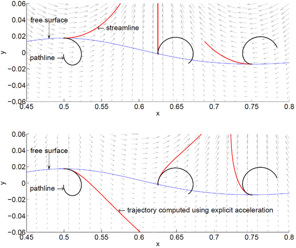
Until [4], the SL-PFEM framework has been developed based on explicit integrators that compute streamlines to approximate the particle´s trajectories. This approach has been successfully applied to many different problems [1, 2, 3, 4]. In fact, the more convection dominates the flow, the better the streamlines approximate the pathlines and the larger the time step that can be used. However, in many problems, convection does not dominate and streamlines computed explicitly at the beginning of the time step are not a good approximation of pathlines. In these cases, small time steps are required to obtain accurate results. An example of this was presented in [5], where a linear wave problem was used as an example. Figure 1 has been extracted from [5], and it shows how pathlines can be approximated by explicit streamlines and by an explicit acceleration method. It can be observed that the explicitly streamline is not such a good approximation and therefore it requires to use very small time steps. On the other hand, including information of the acceleration, even in an explicit way, can considerably improve the approximation. This is the motivation of this work, where an algorithm based on the second order velocity Verlet integrator [6, 7, 8] is proposed, since it has some desirable properties such as being second order accurate over time, time reversible, and symplectic when applied to Hamiltonian systems [8].
This paper is organized as follows: first, the problem of particles moving with a velocity field is introduced. Second, the velocity Verlet scheme is presented to integrate the particle´s equations of motion. Third, the incompressible Navier-Stokes equations are introduced in a semi-Lagrangian framework, where the divergence free condition is enforced using a predictor-multicorrector scheme inspired in the fractional step method. Fourth, a global least-square projector is analysed. And fifth, a number of convergence verification, validation and demonstration cases are carried out.
2. Particles moving with a velocity field
Along the paper, Eulerian variables (mesh values) are written with lower case letters, particle´s variables are written with upper case letters and vectors are written with bold letters. Let be a velocity field, let be a set of particles each of them identified with a label . The position occupied by each particle at time is denoted by , and the velocity of the particle by . If the particle velocity is given by the velocity field , then , and the particles’s trajectories are the pathlines defined by the velocity field . The particle’s equations of motion are:
|
|
(1) | |
|
|
(2) |
where the particle’s acceleration is the rate of change of . An acceleration field can be derived from the velocity field as:
|
|
(3) |
where is the total derivative
|
(4) |
Given an acceleration field, , derived from a velocity field as in Eq. (4), the particles’ velocities and positions can be obtained integrating the equations of motion with initial conditions:
|
|
(5) |
3. Numerical integration of particles’ equations of motion
Let be an acceleration field derived from an unknown velocity field . Given a set of particles with initial position and velocity and . Then the position and velocity at time is obtained integrating the equations of motion:
|
|
(6) | |
|
|
(7) |
In molecular dynamics, a well-known numerical integration scheme for the equations of motion is the velocity Verlet integrator [6,7], which reads:
|
|
(8) | |
|
|
(9) |
where eq. (8) is explicit in time and provides the particle position. We can rewrite eqs. (8) and (9) as:
|
|
(10) | |
|
|
(11) |
where , , .
The incompressible Navier Stokes equations can be written as:
|
|
(12) | |
|
|
(13) |
Where is the fluid pressure, is the fluid density, is the kinematic viscosity and are mass forces. Eq. (12) can be expressed as , where the acceleration field is given by:
|
|
(14) |
Solving the Navier Stokes’ equation in a Lagrangian framework by integrating the fluid particles dynamics is not as simple, since the acceleration field depends on the fluid velocity and the pressure. In order to ensure the divergence free condition of the flow field, the pressure must fulfil an integral equation on the domain. This proves to be very complicated when imposing the continuity condition in a Lagrangian framework.
Below, a Semi-Lagrangian (SL) approach is introduced to overcome the difficulties of estimating the pressure gradient and viscosity terms in a Lagrangian framework. To do so the acceleration field will be obtained in an Eulerian framework by projecting the particle´s velocity field onto the Eulerian space.
Let be a set of fluid particles. Then the equation of motions can be integrated using the velocity Verlet integrator:
|
|
(15) | |
|
|
(16) |
As stated above, this scheme is second order accurate over time. Let´s assume that all variables are known at time . Then the new position of the fluid particles at time can be easily calculated using Eq.(15). Reordering Eq. (16):
|
|
(17) |
where . In order to solve eq. (17), the term will be solved in an Eulerian framework. Then an equivalent Eulerian equation is imposed:
|
|
(18) |
Where is obtained via projection:
|
|
(19) |
is a projector operator that transfer the values of the variables from the set of particle with positions onto the mesh.
We now introduce what we call the coherence condition for the projector:
|
(20) |
where is an arbitrary variable defined on the Eulerian framework. This condition means that the projection of the nodal values interpolated at the particle´s return the original nodal values. If this condition is fulfilled, then from Eq. (18) and (20):
|
|
(21) |
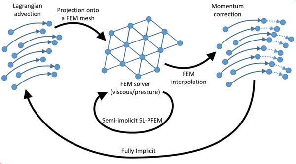
which is equivalent to say that . There is another outcome from the fulfilment of the coherence condition. Figure 2 shows the conceptual implementation of a generic SL-PFEM. In general two iterative loops are required to avoid any sort of splitting error. However, if the coherence condition is fulfilled, there is no need of iterating at the outer loop. This is because the correction of the particles´ velocities, given by , will be projected back to the mesh as it is, with no further need of correction.
Eq. (18) can be solved iteratively by further splitting into:
|
|
(22) | |
|
|
(23) |
Where is the iteration index. Now in order to obtain the pressure , the continuity condition is imposed. Introducing the continuity equation ( ) into Eq.(23) and reordering
|
|
(24) |
Once the iterative process between Eqs. (22)-(23) has converged, from eq. (18) we obtain:
|
|
(25) |
In the previous section, a projector operator was introduced to project the particle´s variables onto the Eulerian space. Then, a strategy to solve the acceleration due to the pressure gradient and viscous terms can be formulated in an Eulerian framework.
The finite element method (FEM) is introduced to solve Eq. (22) and (24). First, we need to discretize it in space using a finite element mesh. Then, any intrinsic dependent variable can be expressed as:
|
|
(26) |
where is the set of mesh nodes, are the classic Finite Element (FE) linear shape functions, and are the nodal values. And let be the vector of nodal values .
Once the spatial discretization is set with a FE mesh, the projector operator must transfer values from particles onto the background mesh following Eq. (21):
|
|
(27) |
Where must fulfil the condition given in Eq. (20) leading to:
|
|
(28) |
Using the FE Galerkin method as in [9,10] to solve the variational formulation of Eqs. (22) and (24) we get:
|
|
(29) | |
|
|
(30) |
Where is the FE mass matrix, is the FE Laplacian matrix, is the FE gradient matrix, and is the FE divergence matrix. Once the iterative loop over converges, then the new acceleration field is obtained from Eq. (18). The convergence criteria used for the pressure and velocity are:
|
|
(31) | |
|
|
(32) |
5. Global least square projector
Let be a set of values carried by a set of particles and be the set of projected values on the mesh nodes. The projector operator used in this work is based on the minimization of the global least square error. The global least square error is given by:
|
|
(33) |
where
|
|
(34) |
Minimizing the least square error via :
|
|
(35) |
Eq. (35) represents a linear system of equation with as many unknowns as mesh nodes. This system can be seen as a discrete version of the classic FE projection. Introducing an interpolated field on the particles :
|
(36) |
leading to and the fulfilment of the coherence condition given in eq. (20).
In order to analyse the order of convergence of the projector, let’s assume that the particles values are given by a continuous and smooth function . Then the equalities and hold, where is the characteristic length of the element where particle is at. Using Eq. (35):
|
|
(37) |
And, the solution to eq. (37) can be expressed as:
|
|
(38) |
Where is the solution of:
|
|
(39) |
Then, the projected value converges with second order accuracy in space:
|
|
(40) |
6. Error accumulation in the SL-PFEM
SL-PFEM methods are prone to accumulate errors as information is passed from the Lagrangian particles onto the background mesh and vice-versa. Those errors are originated in the projection and interpolation steps. And the accumulation of those errors could lead to several undesired effects such as the degradation of the rate of convergence of the numerical scheme, and the incapability to reach a steady state solution. This section aims at demonstrating that the rate of convergence of the proposed scheme is not degraded due to this phenomenon and that second order convergence can be achieved.
Given a velocity field and the corresponding acceleration field , and a set of particles with initial condition , the velocity Verlet algorithm estimates the velocity and position at with second order convergence:
|
|
(41) | |
|
|
(42) |
Now, we will evaluate the error accumulation over time, by estimating the error in the Lagrangian integration of a given acceleration field and subsequent mesh projection-interpolation. Let us consider a space discretization using a FE mesh, in which the given acceleration field is approximated by an interpolated field, as follows:
|
|
(43) |
The velocity at the mesh nodes is initiated from the initial particle velocity through the projection:
|
|
(44) |
Where is the projection error. The projected velocity is then interpolated back to the particles using the projected values:
|
|
(45) |
Then the interpolation error has to be taken into account (both for the velocity and acceleration):
|
(46) |
Finally, the Verlet integrator is used to obtain the particles’ position and velocities:
|
|
(47) | |
|
|
(48) |
Considering that the projector and the interpolator are second order accurate, and using Eq. (8)-(9):
|
|
(49) | |
|
|
(50) |
Which reads:
|
|
(51) | |
|
|
(52) |
Eqs. (51)-(52) show that the error for the first time step is . It is straightforward to show that the resulting errors for the following time steps are those related to the accumulation, which reads:
|
|
(53) | |
|
|
(54) |
resulting in a second order scheme in space and time.
It is obvious that, when solving the Navier-Stokes equations, the exact acceleration field is not known. On the contrary, it must be estimated. In this work, a FE Galerkin method is used to solve the pressure and viscous terms, which is a second order accurate method [9]. Then, this error is also interpolated to the particles and has to be added to the interpolation error considered previously. However, this error does not degrades the rate of convergence of the method since it is second order, too.
As a conclusion, the accumulated error of the projected velocity is:
|
|
(55) |
Then:
|
|
(56) |
7. Convergence analyses
This section presents different examples showing the rate of convergence of the SL-PFEM presented.
1.4 Linear wave trajectories
As it was pointed out in the introduction, for non-dominant convective flows the explicit streamlines computed at the beginning of the time step are not good approximants to pathlines and therefore small time steps are required to achieve accurate results [5]. The flow field induced by a linear wave is a good example used to demonstrate this point. And, if information regarding the acceleration is introduced, the required time step can be increased (see Figure 1).
In this section, the velocity Verlet algorithm is used to estimate the trajectory of a particle moving in the acceleration field induced by the velocities of a linear wave. The 2D velocity potential of an Airy wave with mean free surface located at is given by:
|
|
(57) |
Where is the velocity potential, is the wave amplitude, is the wave number and is the wave length, is the water depth, is the wave angular frequency and is the wave period, and are the vertical and horizontal spatial coordinates, is time. The velocity field is obtained as the gradient of the velocity potential . Then, the corresponding acceleration field is obtained via . Figure 1 shows the velocity field induced by a linear wave. Using the velocity Verlet integrator we obtain the following equations for the position of the particle and its velocity components:
|
|
(58) | |
|
|
(59) | |
|
|
(60) | |
|
|
(61) |
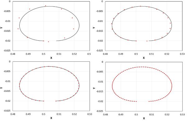
The velocity Verlet has been used to estimate the particle trajectory due to a linear wave with , , , and and with initial position and . The trajectory has been estimated for several time steps ( , , , and ), using the analytical solution for the initial velocity. Figure 3 compares the analytical solution of the trajectory for one wave period with the numerical ones. Comparing the final position of the analytical solution and the numerical ones, an error estimate is obtained. We use this error to carry out a convergence analysis (Table 1).
| X | vx(T) | vy(T) | Error V | |||
| Analytical | 0.508308 | -0.020000 | -0.09850702 | -0.00238937 | ||
| 0.503153 | -0.020397 | 0.00517037 | -0.09850997 | -0.00178868 | 0.00060070 | |
| 0.507039 | -0.020091 | 0.00127241 | -0.09851727 | -0.00222848 | 0.00016122 | |
| 0.507992 | -0.020015 | 0.00031649 | -0.09851019 | -0.00234849 | 0.00004100 | |
| 0.508229 | -0.019997 | 7.9029E-05 | -0.09850785 | -0.00237911 | 0.00001029 |
Now, we will integrate Eqs. (1)-(2) using the semi-Lagrangian approach given the acceleration field induced by a linear wave. The acceleration and velocities at the mesh nodes ( and ) are initialized with the analytical values. The particle’s initial velocities and accelerations are interpolated from the mesh initial values ( and ) . Afterwards, during the simulation the acceleration field is imposed on the mesh nodes and interpolated at the particles, while the velocities are obtained via the semi-Lagrangian approach. The algorithm reads as follows:
Step 1: Move particles from to :
Step 2: Interpolate the particle’s acceleration at the new position:
Step 3: The new particle´s velocity is updated:
Step 4: The particle´s velocities are projected onto the mesh to obtain the new velocity field on the background mesh:
In order to achieve second order convergence, each step must be at least second order in time and space. Step 1 has already been demonstrated that is second order. Step 2 interpolates from the mesh values to the particles using the FE linear shape functions. This interpolation is second order as demonstrated in [3]. Step 3 integrates the velocity in time with a Crank-Nicolson scheme, which is known to be second order in time. And finally, Step 4 is the projection step using the global least square projector which, in the previous section has been demonstrated to be second order in space and time.
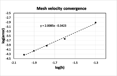
The time step has been setup such that , being the characteristic mesh size. Table 2 provides the values of the mean quadratic error (MQE) of the velocity on the mesh and Figure 4 shows that the rate of convergence is of second order, as expected.
| 1.226E-03 | |
| 2.345E-04 | |
| 1.176E-04 | |
| 6.951E-05 | |
| 4.742E-05 |
1.5 Lid driven cavity flow.
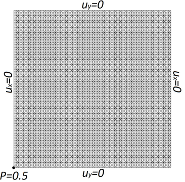
The particulars for this case study are given in Table 3, and Figure 5 shows the discretization used and the boundary conditions applied. An average of 2 iterations is only required for convergence.
Although the steady state solution is achieved after one thousand time steps, the simulation time has been set to to verify whether the steady state solution shows symptoms of error accumulation.
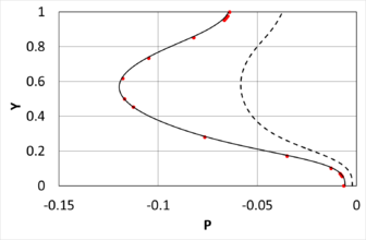
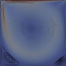
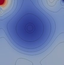
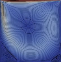
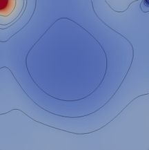
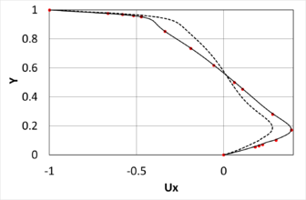
The results obtained with the present second-order Verlet-SLPFEM are compared to those obtained using a high resolution spectral method in [11]. Also results are shown for a first-order SL-PFEM based on the Backward Euler integrator for the velocity equation. Figure 6 compares the streamlines and Figure 7 compares the horizontal velocity and pressure at the mid-section. While the second-order SL-PFEM based on the Verlet algorithm provides very similar results to those of [11], the first-order SL-PFEM based on the Euler scheme produces a highly diffusive solution on the pressure and velocity. Despite being a steady-state problem the first-order method is incapable of achieving the right solution with the current time step. It would require a significant reduction of the time step, which leads to a significant increase of CPU time. On the other hand, the second-order scheme produces an accurate solution for the current time step.
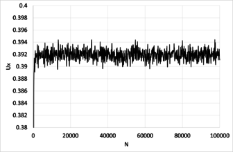
Figure 8 shows the evolution of the horizontal velocity at the node located at (x,y)=(0.5,0.175). It is observed that an average of 0.392 meters per second is obtained with a variance of 0.001 m/s approximately. No symptoms of error accumulation are observed.
| Lid velocity | |
| Reynolds number | |
| Domain size | |
| Domain discretization | |
| Number of triangle elements | |
| Number of nodes | |
| Average number of particles per element | |
| Mesh size | |
| Time step | |
| Courant number | |
| Simulation time | |
| Sampling time |
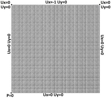
|
|
|
|
|
1.6 Two-dimensional Taylor-Green vortex.
The two-dimensional Taylor-Green vortex problem is used to evaluate the convergence order of the numerical strategy solving an incompressible flow problem for which an analytical solution is known. The analytical solution is given by:
|
(62) |
where is the kinematic viscosity. The problem is solved using a square domain and setting slip boundary conditions for the velocity. Also, to prevent the pressure to be undetermined, the following condition is imposed at :
|
|
(63) |
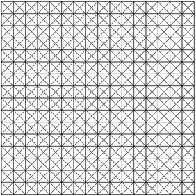
The velocity and pressure field are initialized at with the analytical solution. The simulation is carried out until a final time of is reached. Table 4 provides the values of the mesh size, time step, and the number of time steps computed. Figure 9 shows the mesh used for case 2.
| Case | Mesh size | Time step | Number of
time steps |
| 1 | 50 | ||
| 2 | 100 | ||
| 3 | 150 | ||
| 4 | 200 | ||
| 5 | 300 | ||
| 6 | 400 |
Figure 10 shows the convergence of the proposed algorithm. It can be seen that both, pressure and velocity converge with second order convergence rate.
1.7 Two-dimensional Steady Taylor-Green vortex.
A modified version of the two-dimensional Taylor-Green vortex problem is used to evaluate the convergence order of the numerical strategy solving an incompressible flow problem for which an analytical solution is known. In this version, a mass force is introduced to replace the energy dissipated by the viscous terms, so that a steady solution is obtained. The mass force to be introduced is:
|
(64) |
and the analytical solution to the problem is:
|
(65) |
The problem is solved with ( ). The fluid domain is a square of . Slip boundary conditions are used for the velocity. Also, to prevent the pressure to be undetermined, the following Dirichlet condition is imposed:
|
|
(66) |
The velocity and pressure field are initialized with the analytical solution. And average of 2 iterations is only required for convergence. The simulation is carried out for . Based on the maximum velocity ( ), the Courant number used is . The case is initiated with 3 particles per element, and particles are removed when it exceeds 6 particles per element. At the end of the simulation the average number of particles per element is slightly lower than 3.
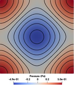
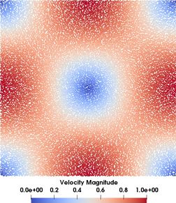
Table 5 provides the values of the mesh size, time step, and the number of time steps computed. Figure 11 shows an intermediate mesh used in the analysis. Figure 12 how the pressure on the mesh and the particle’s velocity obtained for case 64. Both results are quite close to the analytical solution. For this case, the root mean square error is in the order of 0.003 for both, velocity and pressure.
| Case | Mesh size | Time step | Number of
time steps |
| 16 | 1000 | ||
| 24 | 1500 | ||
| 32 | 2000 | ||
| 48 | 3000 | ||
| 64 | 4000 | ||
| 96 | 6000 | ||
| 128 | 8000 | ||
| 192 | 12000 |
|
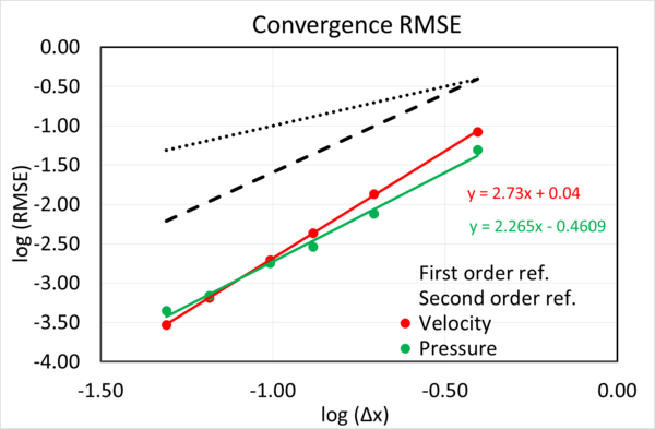
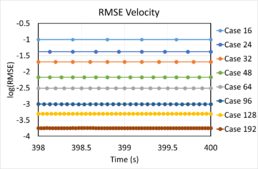
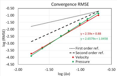
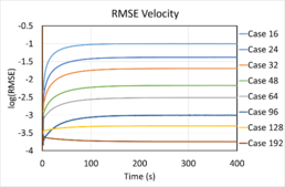
Figure 13 shows the evolution of the errors along the simulation. It is observed that the errors achieved a constant value. Hence no symptoms of error accumulation over time is appreciated. Figure 14 provides the rate of convergence obtained using an average of three particles per element. The root mean square error (RMSE) has been used for the analysis. Table 6 shows the convergence of the proposed algorithm for pressure and velocity.
|
| Convergence Rate | |
| Velocity | Pressure |
| 2.59 | 2.66 |
While in an Eulerian method all dependent variables remain unchanged once the steady state solution is reached, this is not the case in the SL-PFEM method. From the point of view of the particles, the flow is never steady since the intrinsic variables they transport are continually changing.
If a SL-PFEM is not properly tailored, then the error accumulation will make the method to be incapable of computing a steady-state solution. This is because the accumulation of errors along the simulation time will eventually cause a numerical blow up. The present SL-PFEM formulation is capable of computing steady state solutions without errors concerns.
1.8 Three-dimensional flow past a cylinder.
The three dimensional flow around a cylinder is simulated to assess the suitability of the present method for solving three dimensional problems. The particulars of the problem are given in Table 7. An average of 2-3 iterations are only required for convergence.
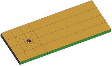
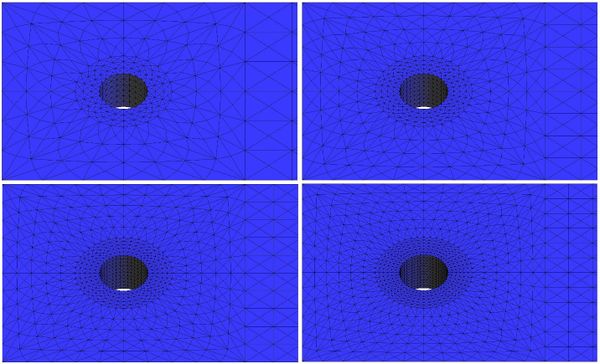
For a Reynolds number of 200 and an aspect ratio of the cylinder height (H) to the cylinder diameter (D) of H/D=1, the flow behaves as a two dimensional flow [12]. A three dimensional structured mesh with five levels of refinement has been used, keeping the Courant number constant. Figure 15 shows the computational domain used, and Figure 16 shows the corresponding meshes used in this analysis. The particulars for each mesh are provided in Table 8, as well as the total number of time steps simulated. In average, two particles per elements are used.
| 1 | 0.1333 | 0.0667 | 62208 | 14487 | 1500 |
| 2 | 0.1 | 0.05 | 147456 | 33412 | 2000 |
| 3 | 0.08 | 0.04 | 288000 | 64185 | 2500 |
| 4 | 0.0667 | 0.0333 | 497664 | 109686 | 3000 |
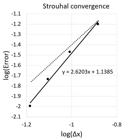
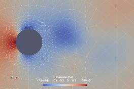
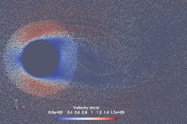
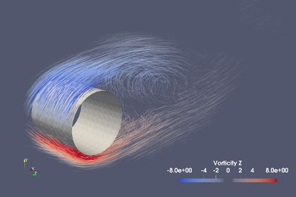
Table 9 provides the Strouhal numbers obtained in each case study. It is observed how the lift force amplitude and the Strouhal number converge towards values of 0.27 and 0.196, respectively. Figure 17 plots the logarithmic errors for the Strouhal number versus the logarithmic mesh size for each case study. Comparing with the second order reference line, it is observed that the convergence rate of the Strouhal number is close to second order. Figure 18 and Figure 19 provides a snapshot of the pressure field, particles velocities, streamlines and vorticity for Case 2.
| 1 | 0.133 | 0.0630 | 0.177 |
| 2 | 0.162 | 0.0339 | 0.255 |
| 3 | 0.178 | 0.0184 | 0.246 |
| 4 | 0.186 | 0.0101 | 0.258 |
| Ref. [12] | 0.196 |
Conclusions
In this paper, a second order semi-Lagrangian (SL) method for solving the incompressible Navier-Stokes equations has been presented within the framework of the Particle Finite Element Method (PFEM). The method is based on the velocity Verlet integrator, which offers an explicit formulation for particle tracking with good numerical properties. Therefore, particles only need to be transported once per time step, which makes this integrator very attractive for the semi-Lagrangian PFEM (SL-PFEM). The algorithm is completed with a predictor-multicorrector scheme for integrating the velocity correction using the Finite Element Method. A second order global least square projector is used to make sure that the coherence condition is fulfilled, which avoids the need of iterating and projecting more than once per time step. The proposed method has been tested for different types of flows in two and three dimensions, and the second order rate of convergence has been achieved. Moreover, it has been shown that there are no symptoms of error accumulation along time, which is a major concern for semi-Lagrangian schemes because it could compromise the rate of convergence and its capability to compute steady-state problems.
Acknowledgements
This work relates to Department of the Navy Grant N62909-16-1-2236 issued by Office of Naval Research Global. The United States Government has a royalty-free licence throughout the world in all copyrightable material contained herein.
Conflict of interest
On behalf of all authors, the corresponding author states that there is no conflict of interest
References
[1] S.R. Idelsohn, J. Marti, P. Becker, E. Oñate: Analysis of multifluid flows with large time steps using the particle finite element method. International Journal for Numerical Methods in Fluids 75(9), 621–644 (2014). DOI 10.1002/fld.3908.
[2] S. R. Idelsohn, N. Nigro, A. Limache, E. Oñate: Large time-step explicit integration method for solving problems with dominant convection. Computer Methods in Applied Mechanics and Engineering 217-220, 168–185 (2012). DOI 10.1016/j.cma.2011.12. 008.
[3] P. Becker, S. R. Idelsohn, E. Oñate. A unified monolithic approach for multi-fluid flows and fluidâASstructure interaction using the Particle Finite Element Method with fixed mesh. Computational Mechanics (2014). DOI 10.1007/s00466-014-1107-0
[4] J. M. Gimenez, H. J. Aguerrea, S. R. Idelsohnd, N. M. Nigro. A space-time second-order particle-based method to solve ow problems on arbitrary meshes. Accepted for publication in Journal of Computational Physics. DOI 10.1016/j.jcp.2018.11.034
[5] P. Nadukandi, B. Servan-Camas, P. A. Becker, and J. Garcia-Espinosa. Seakeeping with the semi-Lagrangian Particle Finite Element Method. Comp. Part. Mech. (2017) 4: 321. DOI 10.1007/s40571-016-0127-2
[6] L. Verlet. Computer "Experiments" on Classical Fluids. I. Thermodynamical properties of Lenard-Jones Molecules. Phys. Rev. E. 59(5), 98-103. (1967)
[7] W. C. Swope, H. C. Andersen, P. H. Berens, and K. R. Wilson. A computer simulation method for the calculation of equilibrium constants for the formation of physical clusters of molecules: Application to small water clusters. J. Chem. Phys. 76, 637 (1982). DOI 10.1063/1.442716.
[8] E. Hairer, C. Lubich and G. Wanner (2003). Geometric numerical integration illustrated by the Störmer–Verlet method. Acta Numerica, 12, pp 399-450. DOI 10.1017/S0962492902000144
[9] J. Garcia-Espinosa, A. Valls, and E. Oñate. ODDLS: A new unstructured mesh finite element method for the analysis of free surface flow problems Int. J. Numer. Meth. Engng 76(9) 1297-1470 (2008).
[10] E. Oñate , J. García-Espinosa, S.R. Idelsohn, F. Del Pin. Finite calculus formulations for finite element analysis of incompressible flows. Eulerian, ALE and Lagrangian approaches. Comput. Methods Appl. Mech. Engrg. 195 3001–3037 (2006).
[11] O. Botella and R. Peyret. Benchmark spectral results on the lid-driven cavity flow. Computers & Fluids Vol. 27, No. 4, pp. 421-433, 1998.
[12] H. Jiang and L. Cheng. Strouhal Reynolds number relationship for flow past a circular cylinder. J. Fluid Mech. (2017), vol. 832, pp. 170-188.
Document information
Published on 01/01/2020
DOI: 10.1007/s40571-019-00258-9
Licence: CC BY-NC-SA license
