Abstract
An adaptive Finite Point Method (FPM) for solving aeroelastic compressible flow problems is presented. The numerical methodology is based on a meshless upwind-biased discretization of the Euler equations, written in arbitrary Lagrangian-Eulerian (ALE) form, and integrated in time by means of a dual-time steeping technique. This procedure allows achieving accurate solutions circumventing stability constraints of time marching schemes but profiting from its explicit features. In order to exploit the meshless potential of the method, the domain deformation approach implemented is based on the spring network analogy and h-adaptivity is also employed in the computations. Several numerical examples involving typical aeroelastic problems illustrate the performance of the proposed technique. Moreover, evidence about the computational cost and parallel performance of the method is given.
1. INTRODUCTION
Aeroelastic problems are of paramount importance in aerospace, mechanical and civil engineering and numerous approaches involving different levels of complexity have been proposed for solving them. Since the beginning of the last century, the study of aeroelastic instabilities such as lift divergence, flutter and gust response have been extensively addressed through experimental, analytical and numerical approaches, gaining considerable experience in these issues. However, present trends in aeronautical design pursuing reduced structural weight and enhanced operational performances demand improved aeroelastic analyses which, in many cases, go beyond the scope of classical aeroelastic design methodologies [1]. Thus, more complex analyses based on Euler or Navier-Stokes equations and fully coupled time-accurate approaches must often be considered.
The solution of Euler or Navier-Stokes equations on moving domains involves certain difficulties regarding mesh motion and deformation. Moreover, adaptive refinement techniques are also frequently needed to achieve enough mesh resolution to capture local behaviour and/or keep acceptable mesh topology in highly deformed zones of the analysis domain. These facts make the problem solution difficult and increase the computational cost, causing sometimes failure of the numerical approach to suit the requirements of a practical design tool. In the context of the aforementioned problems, meshless methodologies (see [2] for an overview) represent an alternative to conventional discretization techniques. The fact that meshless methods do not exhibit any of the topological restrictions associated with a mesh makes them especially well suited for tackling moving or deformable domain problems.
In the last two decades, numerous meshless techniques aimed at dealing with steady and unsteady compressible flow problems [3-10] have been developed (cf. [11] for a comparative analysis of some popular discretization approaches). Moreover, applications to unsteady problems accounting for body motion have also been explored with success in a meshless context through domain deformation techniques or small perturbation boundary conditions [12-14]. All in all, meshless features have been increasingly exploited and numerous advantages over conventional discretization techniques have been discovered. However, certain implementation aspects, mainly robustness and efficiency, still arise doubts about their real benefits. This causes meshless methods to occupy a relegated place in the current scenario of computational methods. With the objective to contribute to this discussion, we present an application of the Finite Point Method (FPM) [4, 6, 9] to the adaptive solution of aerolastic compressible flow problems, for considering this field in which the exploitation of meshless features could render important benefits.
This work is organized as follows. Section 2 outlines the main aspects of the finite point method and gives some implementation details. The equations to be solved are presented in Section 3 and the scheme we propose for its solution is outlined in Section 4. Sections 5 and 6 describe the domain deformation and h-adaptive techniques respectively. Aimed at assessing the performance of the proposed methodology, several numerical applications are presented in Section 7. Finally, the most relevant conclusions of this work are drawn in Section 8.
2. THE FINITE POINT METHOD
Suppose u(x) is a field function defined in a closed analysis domain Ω ∈ d (d=1, 2 or 3) which is discretized by a set of points xi ( ![]() ) and Ωi are local clouds of points covering Ω. Let each local cloud consist of np points resulting from a point xi called star point and a set of points xj surrounding it. Then, an approximation to the function u(x) in Ωi can be stated as
) and Ωi are local clouds of points covering Ω. Let each local cloud consist of np points resulting from a point xi called star point and a set of points xj surrounding it. Then, an approximation to the function u(x) in Ωi can be stated as
|
|
(1) |
where p T is a complete polynomial base in d [15] and α is a vector of unknown coefficients. According to Eq. (1), function u(x) can be sampled at each point by
|
|
(2) |
where is the sought function value at , is an approximated value at that point and . Assuming the system (2) results overdetermined and an approximate solution is obtained by minimizing the following discrete error norm
|
|
(3) |
in which is a fixed compact-support weighting function centred on the star point of the cloud (Fixed Least-Squares (FLS) procedure). The minimization of Eq. (3) with respect to α ( =0) leads to the following equation system
|
|
(4) |
where A = PTΦ(x)P, B = PTΦ(x) and Φ(x) = diag(φi( x j)). Then, the vector of unknown coefficients can be readily found
|
|
(5) |
and the approximate value of u(x) at the star point of the cloud (the point where the weighting function was located) is obtained from Eq. (1)
|
|
(6) |
As a consequence of having adopted a fixed weighting function, matrices A and B are constant in Ωi. Thus, the l-order derivatives of the unknown function at xi result
|
|
(7) |
It is possible to demonstrate [16] that the FPM approximation satisfies the partition of unity () and partition of nullities () properties and any function included in the polynomial approximation basis can be exactly reproduced. In particular, the partition of nullities property is essential to develop Local Extremum Diminishing (LED) type flow solvers as will be shown in Section 4.
Remarks
- In this work 2nd-order complete polynomial bases are used. Although further investigation on this issue is still needed, according to our experience these bases achieve the best result regarding accuracy, robustness and computational cost.
- The FLS procedure reduces the computational cost considerably, but the resulting approximation is globally and locally discontinuous and should be considered only valid (accurate) at the star point of the cloud where the weighting function is located. As a consequence of this, the discrete system of equations is solved by point collocation.
- The approximation coefficients α can be obtained by inverting matrix A in Eq. (5) but ill-conditioning can lead to numerical inaccuracies depending on the spatial distribution of points in the local cloud. While 2D approximations are normally insensitive to this problem and can be solved satisfactorily by matrix inversion, numerical misbehaviours related to cloud geometrical features are frequently seen in 3D. For such cases, the authors presented in [15] an alternative QR-based approach which has proven to improve accuracy and robustness.
2.1 The weighting function
Different possibilities exist for defining the weighting function in Eq. (3). The typical choice in the FPM is a Gaussian function located at the star point of the cloud. Namely,
|
|
(8) |
with d = x - x , = /w and = d (). The parameters w, k and govern the functional shape of the weighting function and could have important effects on the resulting numerical approximation. Some guidelines for its setting are given in [15].
2.2 Discretization of the analysis domain: the point generator
Even though not any point discretization is valid for meshless computations (especially when the problem exhibits complex geometrical/flow features), the fact that topology is not a matter of concern allows achieving proper point discretizations faster and cheaper. Hence, it is expected that any point generation technique employed makes the most of this advantage. A highly effective technique is that developed by Calvo [17], in which the point generation starts from a user-supplied boundary grid and inserts new points in the centre of empty spheres filling Ω through an optimization driven point insertion procedure. This incremental quality technique based on unconstrained Delaunay tetrahedralization allows achieving a quality point discretization with approximated cost O(n) [18, 19]. In addition to the low computational cost, this technique has other advantages that reduce model developing time significantly. For instance, the input boundary mesh may contain any type of elements and be non-conformal. Furthermore, the point spacing inside the domain does not need to be specified, it is automatically assigned by computing linear variations between grid boundary sizes. These characteristics make the Calvo’s point generation technique highly competitive with respect to other approaches used in mesh-based discretization methods.
2.3 Construction of local clouds
Cloud construction techniques in LSQ-based meshless approximations must be aimed at achieving point distributions which facilitate (from a mathematical point of view) the solution of the minimization problem. Moreover, these procedures should be able to deal with all the geometrical features found in practical application problems with robustness and a low computational cost. In this regard, we follow the technique proposed by Löhner et al. [6], which has proven effective. The procedure is summarized in the next.
Given a point discretization of the computational domain and a set of boundary points with associated geometrical data, a maximum (npmax) and minimum (npmin) number of points in the local cloud and an initial search radius are set. The parameter npmin is chosen to double the minimum number of points required for setting the approximation while npmax is about 20 and 50 in 2D and 3D problems respectively (using 2nd-order polynomial bases). Having defined these parameters, the construction of the local clouds and the numerical approximation proceeds as follows.
For each star point xi, all points within the initial search radius are sought by using bins. Then, these points are filtered according to boundary restrictions by using some visibility criteria (cf. [6, 9]) which ensure physical compatibility in the local cloud. If the number of compatible points is lower than a given threshold (about 60 in 2D and 150 in 3D) the search radius is increased and the search-filtering procedure is repeated. Once the minimum number of points is met, a local Delaunay grid is computed with these points and only the layer of nearest neighbours of xi is retained and stored. This procedure is repeated for all points in the domain. Note that if some kind of connectivity between points is available (typically from point generation stages), it can be used to speed up the construction of the neighbours layers by simplifying spatial search and, in some cases, avoiding the local Delaunay gridding. The filtering stage is, in general, always required to satisfy boundary restrictions.
Then, the local clouds and their related numerical approximations are constructed. To this end, for each star point xi a local cloud is initialized with its layer of nearest neighbours. If the number of points is lower than npmin, further points are added from an auxiliary neighbours list until the condition is met (this auxiliary list is constructed by adding points according to layers and ordering them by ascendant distances from the star point at hand). Next, the shape function and its derivatives are computed and proven to satisfy a given quality criteria [15]. If the test is not successful, additional points are added from the auxiliary list while np≤npmax. In our experience, npmax = 50 is enough to achieve a suitable approximation in highly distorted clouds. In addition, an enlargement of the local support beyond the mentioned limits is not justified in practice because of two main reasons. First, the computational cost of the problem solution grows very rapidly with the cloud size and, second, the potential improvement in the approximation is often small, with the added risk of degrading the local approximation to the problem variables due to the excessive smearing typically found in large local supports.
It should also be noticed that including the layer of Delaunay nearest neighbours into the local clouds enforces the overlapping between adjacent clouds. This fact has shown to improve the quality of the local approximation as well as to be helpful when dealing with problems governed by conservation laws. Moreover, the nearest neighbours data provide efficient means to implement several computational procedures as will be shown through this work.
3. FLUID GOVERNING EQUATIONS
The fluid flow in this work is assumed to be governed by the compressible Euler equations. Aimed at facilitating the treatment of moving boundaries inside the analysis domain the problem is described in an arbitrary Lagrangian-Eulerian (ALE) frame of reference. In conservative differential form these equations can be written as [20]
|
|
(9) |
where U is the conservative variables vector, F k the advective flux vector in the coordinate direction xk and S is a source vector term accounting for domain deformation. Namely,
|
|
(10) |
where , p and e and are the fluid density, pressure and total energy respectively. The Cartesian components of the fluid velocity are u and wdenotes the components of the discrete points velocity; is the Kronecker delta and subscripts i,k = 1,3. The following state relation for a perfect gas closes the system of equations 9
|
|
(11) |
being the specific heat ratio. The solution of Eq 9 in a closed domain with boundary = requires appropriate initial and boundary conditions. The initial conditions employed in this work correspond, in general, to the steady flow solution of the problem at hand, i.e. at . The boundary conditions employed for are far-field conditions on outer boundaries and slip conditions on solid boundaries . In the case of far-field boundaries, the flux in the outward normal direction at each x is prescribed by solving an approximate Riemann problem between U and the far-field state U. Over solid boundaries, slip wall conditions are enforced by
|
|
(12) |
being the unit boundary normal vector at point x . The spatial position of the discrete points x and their velocities w as well as the boundary normal vectors are obtained from prescribed or computed movements for . We will go back to this point later in Section 5.
4. THE FLOW SOLVER
A semi-discrete counterpart of the conservation equations (9) which resembles non-oscillatory LED schemes can be obtained by profiting from the partition of nullities property of the FP approximation. This leads to [9],
|
|
(13) |
where is a discrete approximation at x of the conservative variables vector, is an unknown numerical flux computed at the midpoint of the line segment connecting x to another point and . Among the different possibilities that exist for defining the numerical flux, in this work the Roe's approximate Riemann solver is adopted [21]. Thus,
|
|
(14) |
where is a unit vector in the direction of and is the positive Roe matrix calculated in the same direction (see [22] for details). Aimed at increasing the spatial accuracy of the Roe solver, the variables in Eq. 14 are replaced by leftward and rightward higher-order reconstructions obtained by limited MUSCL extrapolation along the vector [6]. The Van Albada limiter is adopted.
4.1 Discretization in time
The Jameson’s dual-time steeping approach [23] is adopted to integrate in time the semi-discrete equations (13). This procedure allows solving implicitly each physical time increment by means of inner explicit iterations in a fictitious time. To this end, a 2nd-order backward difference operator is applied to the time derivative in Eqs. (13) leading to
|
|
(15) |
where -R(U) is the right-hand side of the system 13 and the subscripts (·) and () have been omitted for the sake of clarity. Next, for a given increment in physical time t, a modified (unsteady) residual is defined from Eq. 15 as
|
|
(16) |
verifying that approaches as . In order to solve Eq. 16 in an explicit manner, a temporal derivative with respect to a fictitious time t* is introduced. This leads to
|
|
(17) |
and this system is driven to the steady state by means of a multi-stage scheme. Therefore, the intermediate solution is advanced from a fictitious time level m to a level m+1 by
|
|
(18) |
being integration coefficients depending on the number of stages employed (see for instance [24]) and a fictitious local time step which must be bounded due to stability requirements. This can be computed by
|
|
(19) |
where denotes the Courant number, c is the speed of sound and the rest of the variables have been previously defined. In addition to local time steeping, implicit residual smoothing [25] is applied to accelerate the convergence of the system 17 to the steady state. Notice that the explicit treatment of the term could lead to numerical instabilities if the physical time step is small [26]. Fortunately, this problem can be easily overcome by treating implicitly that term in Eq. 18, cf. [27] for further details.
The difference between (·) and () parameters has been explained in Section 2. Taking into account that R(U) is a function of U x , the following linear system has to be solved to recover the (·) parameters from the approximate ones
|
|
(20) |
Although system 20 has excellent properties and can be solved by a few Gauss-Seidel iterations with little computational cost, numerical experiments have demonstrated that in some cases this step could be skipped assuming without causing any negative impact on the accuracy of the numerical solution. This behaviour could be explained to a large extent due to the fact that (·) and () parameters become very closer in well-behaved finite point approximations (the shape functions tend to interpolate point data).
5. POINTS MOVEMENT STRATEGY
The simulation of unsteady problems involving deforming or moving bodies requires the domain discretization to conform continuously to the instantaneous body shape. According to the analysis geometry and the motion involved, the domain deformation technique could vary from simple rigid rotations or translations to more complex operations if the body modifies its shape or relative motions between several bodies must be accounted for. An overview of the strategies usually proposed to deal with these issues is presented in [20]. In this work a spring network approach is adopted [28, 29]. Therefore, the displacement of any interior point in response to instantaneous displacements of body points are obtained by enforcing the static equilibrium of the forces exerted by all the points connected through the 's layer of nearest neighbours (outer boundary points are considered to be fixed). This leads to a system of equations written in terms of displacements which is solved by Jacobi iterations,
|
|
(21) |
being k the iteration counter, and displacement vectors of points and respectively and a link stiffness which prevents the clouds near the boundary from excessive distortion ( is adopted). After some iterations the position of the discrete points is updated according to
|
|
(22) |
and its velocities are simply estimated by being the physical time increment employed in the simulation. Notice that an accurate solution of the system (21) is not required; in this work 10-30 iterations showed enough to propagate the body displacements inside the domain achieving a smooth distortion of the discretization. For very large body displacements the link stiffness can be raised by increasing parameter p.
Once the new positions of the discrete points are obtained the boundary normal vectors and other discretization related data are updated accordingly. In addition, although the cloud connectivity remains unchanged after domain deformation, the relative position of its points does not. Consequently, the local approximation must be re-computed in the affected clouds.
6. ADAPTIVITY
Unsteady compressible flow problems typically involve evolving discontinuities resulting from flow unsteadiness or body motions. Accurate solutions require these localized flow features to be properly resolved and this requires a domain resolution which could be unaffordable in many engineering analyses. An efficient way to deal with these problems with accuracy while keeping the computational cost acceptable is by using h-adaptivity. Moreover, h-adaptivity constitutes a good complement to domain deformation techniques because it can regenerate in a local manner highly distorted zones in the analysis domain improving the quality of the discretization. The reduced discretization restrictions found in meshless methods makes them an ideal context to implement h-adaptive strategies. In this work the main lines of the methodology developed by the authors in [9, 30] is followed, although some modifications are introduced to increase the effectiveness and robustness of the technique. Next, the main aspects of the adaptive strategy are described.
6.1 Refinement/coarsening indicator
Local clouds in the analysis domain where either refinement or coarsening is required are identified as follows. First, a sensor measuring in an approximate manner the curvature of the density solution field is computed for all points in the domain by
|
|
(23) |
being the number of points in the layer of nearest neighbours of and . Next, a smoothed non-dimensional refinement indicator is computed at each star point as
|
|
(24) |
Finally, the logarithm of the smoothed indicator (24) is taken in order to compress the scale of the distribution and its mean value and standard deviation are computed. These values are used to determine local clouds in which refinement or coarsening is required: the star point is tagged for refinement when and, conversely, the point is marked to be removed if . The threshold parameters and must be set according to the problem under study, typical values employed in the examples shown in this work are and . It was observed that this indicator performs better than that employed previously in [9, 30] in capturing strong and smooth features of the flow; in addition, it presents a reduced dependence of the user defined threshold parameters.
6.2 Removal and insertion of points
The adaptive stage begins with the removal of points tagged for deletion. The coarsening of surface grids is performed by collapsing edges with marked nodes and interior volume points are simply deleted from the vertices list. After the removal of points the data structure is updated. It should be noticed that the removal of points is restricted only to the existing points that have been inserted in prior refinement levels.
The surface grids are refined after the coarsening stage. To this end, surface elements having tagged all its nodes are selected and a new point is inserted at its centroid (and the element is subdivided) if the distance from the latter to any other point in the discretization is greater than a minimum element size (set as the minimum nodal distance of its nodes). The minimum nodal distance, which determines the desired level of refinement, is computed for the original points as a percentage of the distance between the point and the nearest neighbour in its cloud; for new points added during refinement stages this distance is obtained from interpolation of the original distribution. Once new boundary points are inserted, its positions (originally coincident with the centroid of the underlying element) are slightly improved by interpolation [31] to avoid excessive faceting of the surfaces in successive element subdivisions. Finally, edge swapping is applied on the affected boundary elements to improve its connectivity and facilitate the insertion and removal of points in future adaptive passes.
In the interior volume, when a cloud of points is selected to be refined, the Voronoi vertices surrounding the star point are computed by means of its Delaunay grid of nearest neighbours. Next, a new point is added at each Voronoi vertex location if the distance from the latter to any existing point is greater than the minimum distance for the cloud and if, in addition, boundary constraints are satisfied (basically, the ray from the star point to any new point added to the cloud cannot pierce any boundary surface). In order to perform the many spatial search operations required during the adaptive stage efficiently, a dynamically updated octree structure is employed.
6.3 Update
Once coarsening and refinement steps are finished, a few steps of a Laplacian smoothing are carried out on the affected area. After that, the clouds of points and the local approximation concerning the new points are constructed. In addition, the data concerning existing clouds of points affected by deletion, insertion of new points or smoothing are re-constructed. Finally, the flow and other problem variables at the new points are obtained as an average of the variables at their previously existing first nearest neighbours.
7. NUMERICAL APPLICATIONS
Four test cases involving typical aeroelastic problems in transonic flow regime are presented in this section with the aim of illustrating the performance of the proposed methodology. Through the examples, various important aspects of the method are discussed.
7.1 NACA wing subject to pitching oscillations
A typical AGARD benchmark for unsteady flow is considered in this example. The problem involves a NACA 0012 airfoil subject to prescribed pitching oscillations [32] and is solved in 3D using a wing with unit chord and span . The analysis domain considers two symmetry lateral planes at the wing tips to simulate two-dimensional flow around the wing and an outer boundary located 10 chords away from the wing in which Riemann freestream boundary conditions are prescribed. The discrete model consists of an unstructured distribution of 33409 points. The freestream Mach number is set to and the instantaneous angle of attack of the wing (in degrees) is varied according to . The reduced frequency is and the pitch axis is located at the quarter chord point. For all the analyses presented in the next, the converged steady solution of the problem is employed to initialize the unsteady simulations.
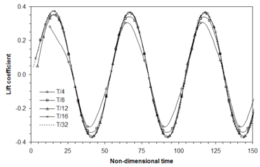
The first analysis is intended to assess the performance of the time integration scheme. To this end, simulations with 4, 8, 12, 16 and 32 physical time steps per oscillation period (T) are performed. At each time increment, the unsteady residual is reduced at least 4 orders of magnitude over its original value (typically 500 iterations were enough). The time evolution of the computed lift coefficients is presented in Figure 1, where it is possible to note the convergence of the solution as the physical time step is reduced.
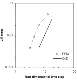
The time accuracy of the numerical scheme is estimated by defining a temporal error as the magnitude of the difference between the lift coefficient computed at time for a given solution and that obtained at the same instant time with the smaller time step computation (). The variation of the temporal error with the time step size is plotted in Figure 2, where a convergence rate close to the design order of accuracy of the scheme is observed.
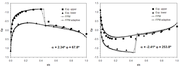
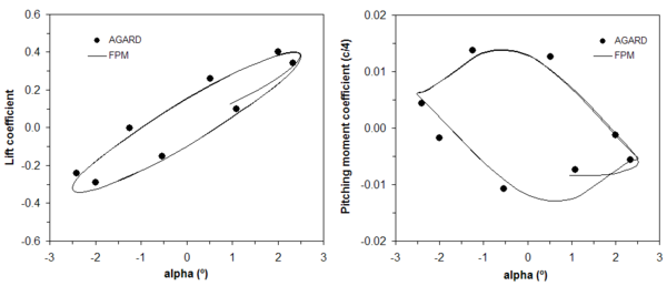
Next, the simulation having 16 physical time steps per oscillation cycle is repeated, but adding 2 h-adaptivity passes per physical time step. On average, no more than 7000 points are added during the adaptive steps while the number of removed points does not exceed 3000, achieving this maximum when the shock wave moves from the upper to the lower side of the wing and vice versa. The computed coefficient of pressure (Cp) along the mid-span of the wing at two instant times (corresponding to phase angles = 67.8 and 253.8) are compared in Figure 3 with those obtained for the original discretization and experimental results [32]. Moreover, the variation of lift and pitching moment coefficient with the instantaneous angle of attack for the adapted solution is compared with experimental results in Figure 4. It must be said that, as the difference found between adapted and non-adapted solutions was very small, the latter is not included in this figure (possibly the original discretization is fine enough to be in the range of converged grid solutions). A good agreement between numerical and experimental results can be observed both in Figures 3 and 4. Finally, refined points distributions in a cut plane along the mid-span of the wing are shown in Figure 5 for two different wing instant positions.
Figure 4. Comparison between computed and experimental force and moment variation with the instant angle of attack for the NACA 0012 wing (adapted solution, ).
7.2 Wing with oscillating flap
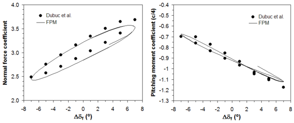
An adaptive calculation of a wing having an oscillating flap is solved in this example to assess the capability of the method to deal with problems involving relative body motion. The section of the wing corresponds to the William airfoil (configuration B) [33] and the flow conditions are defined as in [34]: the freestream Mach number is set to , the instantaneous flap angle (in degrees) is , the reduced frequency and the flap hinge position is located at coordinates . The coordinates are non-dimensional with the chord of the main wing section and the rotation of the flap is counted with respect to its original position in the Williams airfoil. The analysis domain employed is defined similarly to the previous example and discretized by an unstructured distribution of 20713 points. The numerical simulation employs 12 physical time steps per flap oscillation cycle and 2 h-adaptive stages in each are performed. The computed variation of the normal force and pitching moment coefficients as a function of the instantaneous flap angle is compared in Figure 6 with results presented by Dubuc et al. [34] showing a good agreement.
Next, Figure 7 shows two plane cuts of the adapted domain taken at different instant times during the simulation. It is possible to observe the displacement of the shock wake along the main wing and the appearance of a shock on the flap for its maximum incidence angle.
Figure 7. Refined point distributions along a plane passing through the mid-span of the Williams wing. Left: Failed to parse (syntax error): {\textstyle \delta _{f}=0^º}
and Failed to parse (syntax error): {\textstyle \varphi =270º}
- Right
- Failed to parse (syntax error): {\textstyle \delta_{f}=14.0^º}
and Failed to parse (syntax error): {\textstyle \varphi = 90^º.}
7.3 Twist deformation of an ONERA M6 wing
This example concerns the calculation of an ONERA M6 wing subject to twisting deformation about a line passing through the tip quarter chord point [35]. The freestream Mach number is ![]() and the wing incidence
and the wing incidence ![]() . The twist deformation is achieved by forcing the tip section to pitch with (in degrees) while keeping the root section fixed. The instant angle of attack of the intermediate sections is varied linearly along the wing semi-span and the reduced frequency is . The analysis domain includes a symmetry plane and an hemispherical outer freestream boundary.
. The twist deformation is achieved by forcing the tip section to pitch with (in degrees) while keeping the root section fixed. The instant angle of attack of the intermediate sections is varied linearly along the wing semi-span and the reduced frequency is . The analysis domain includes a symmetry plane and an hemispherical outer freestream boundary.
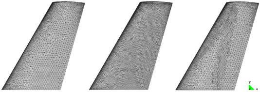
In order to investigate the impact of h-adaptivity from the point of view of accuracy and computational cost two different unstructured domain discretizations are constructed: a fine discretization having 258919 points and a coarse one with 107847 points. In addition, an adapted discretization is obtained from the latter by performing one h-adaptive pass per physical time step. The wing surface grids corresponding to the mentioned discretizations are shown in Figure 8.
Figure 8. Top view of the ONERA M6 wing surface grids. Left: coarse; Center: fine and Right: adapted at φ=0º (the adapted discretization does not change substantially during the twist cycle).
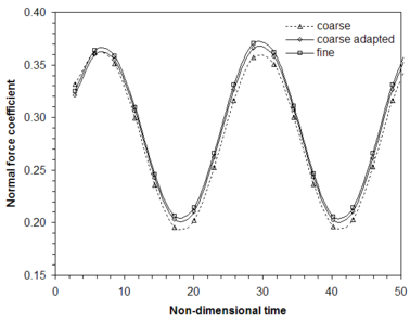
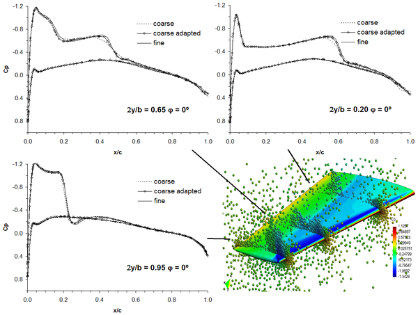
Several twist cycles are simulated with the discretizations defined above running 8 physical time steps per cycle. The number of fictitious time iterations is fixed to 500 and the resultant unsteady residual is reduced approximately 4 orders of magnitude in the coarse and fine simulations but results slightly higher for the adapted run. However, no significant variations in the results were observed. Figure 9 displays the time evolution of the normal force coefficient and some instantaneous Cp distributions along the wing are compared in Figure 10. Even though the number of new points added during the h-adaptivity stages reaches as much the 12% of the number of original points, it is possible to observe that the solution is noticeably improved with respect to the non-adapted coarse simulation.
Figure 9. Time evolution of the normal force computed for the twisting ONERA M6 wing computed with the coarse, fine and adapted coarse discretizations (Δt=T/8).
Aimed at assessing computational cost of the method, the CPU-time required to advance the simulation one physical time step (Δt=T/8, 500 fictitious time iterations) is compared in Table 1 for the coarse, fine and adapted discretizations. The simulations are run in parallel in a desktop computer with IntelCore2 Quad Processor Q9550 @ 2.83 GHz (the code is fully parallelized through OpenMP directives). Table 1 shows that the cost in the adapted simulation is slightly higher than that corresponding to the coarse discretization and low if compared with the fine discretization run. At the same time, the adapted results are much better than those obtained with the coarse discretization and not so different from those corresponding to the fine discretization. Although there could exist some problem (and user setting) dependence in the adaptive results, meshless adaptivity shows effective.
Figure 10. Comparison of instantaneous Cp distributions along 3 sections of the ONERA M6 wing computed for the coarse, fine and adapted discretizations (a view of the latter is displayed at the right bottom).
Table 1. Comparison of CPU-time needed to advance the solution of the twisting ONERA M6 wing a single physical time step (Δt=T/8 and 500 fictitious time iterations). The runs are performed in parallel using 4 threads.
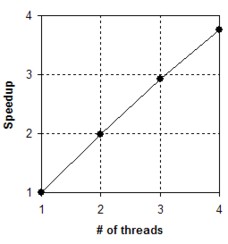
Finally, the parallel speedup observed for the adaptive simulation is depicted in Figure 11. FPM low data dependence allows most of the typical costly operations in the flow computation (even when performing adaptivity) to be carried out in a completely independent manner, thus achieving good parallel performance.
Figure 11. Observed speedup in the ONERA M6 wing adapted simulation (Δt=T/8 and 500 iterations in fictitious time loop).
7.4 Flutter prediction for a NACA 64A010
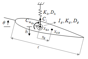
Aimed at demonstrating the applicability of the present methodology to more general aeroelastic analyses, transonic flutter limits for the Isogai wing section [36, 37] are computed. The structural model adopted is a typical section with two degrees of freedom: pitch about the elastic axis θ and plunge h (see Figure 12). In non-dimensional form this system results
|
|
(25) |
where is the ratio of uncoupled natural frequencies and , is the reduced frequency, is the radius of gyration, and are the damping ratios and is the airfoil mass ratio. The equations (25) are converted to a system of ordinary differential equations through state-variables transformation and its solution is carried out by means of a fourth-order Runge-Kutta scheme.
The coupling methodology between the aerodynamic and structural models follows the lines given in [38]. Firstly, the aerodynamic force and moment acting on the body at a physical time level tn+1 are predicted using known values computed at previous time levels, e.g. for quadratic extrapolation. Using the solution at the previous time level as initial condition, the system (25) is solved in order to obtain pitch and plunge displacements of the wing section for time tn+1, the body is moved and the discretization is deformed accordingly. Secondly, the fluid flow equations are solved at physical time tn+1 and a better approximation to the aerodynamic forces acting on the body is computed. These steps are performed until convergence of the aerodynamic forces is reached. Then, the physical time level is increased and the procedure is executed again. In spite of the fact that force convergence was sought in the present simulation, several numerical tests have shown that inner iterations can be neglected without affecting much the accuracy of the numerical results if the physical time increment and the body displacements are not large.
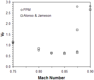
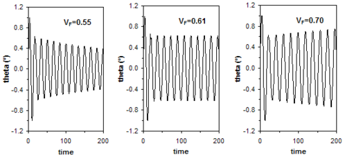
The coupled problem is solved with the following airfoil structural parameters: (measured from the leading edge), , , , and . The discrete analysis domain is two-dimensional and consists of an unstructured distribution of 5568 points. In order to start the computation the wing section is forced to pitch with amplitude 1º about its elastic axis at the natural frequency ωθ (with an initial flow field corresponding to the steady solution at the considered Mach number). After a single period of forced oscillation, the airfoil is set free in pitch and plunge in order to determine the system response. At different Mach numbers, the speed index is varied in order to identify damped, neutral and undamped responses. Flutter instability is considered to occur for a speed index beyond that corresponding to the neutral response of the system and the physical time increment is set at 1/40 of the natural period of the structure in all the computations. Next, the flutter boundary computed for Mach numbers are compared with those obtained by Alonso and Jameson [39] in Figure 13, where a good agreement is observed. Figure 14 presents damped, neutral and undamped responses of the airfoil for . The computed flutter boundary in this case is slightly above ![]() .
.
Figure 14. Damped, neutral and undamped responses computed for NACA 64A010 airfoil at M∞=0.825 (the time scale is non-dimensional).
8. CONCLUSIONS
A Finite Point Method (FPM) for solving compressible aeroelastic problems has been presented. The overall methodology was designed following well-established numerical techniques but aiming at making the most of meshless features. After several tests the preliminary results are satisfactory and reveal various capabilities of the proposed technique to efficiently solve aeroelastic problems. Among them, it must be highlighted, for instance, the versatile and faster point generation technique allowing reduced turn-around times during simulation setup and the possibility to account for body movement or deformation with robustness and a low computational cost. Moreover, the employment of solution adaptive discretizations, which is straightforward in a meshless context, has demonstrated to be particularly useful. Finally, the fair parallel scalability of the method observed in this work on modest desktop computers, indicates that significant time savings could be achieved by exploiting high-performance and modern hardware capabilities (e.g. GPUs).
All in all, the results obtained for the FPM presented are quite encouraging. However, additional efforts are still needed to examine the capabilities of this methodology for aeroelastic analysis further. Future work should focus, especially, on large-scale engineering problems, the employment of high-performance computer hardware and the full exploitation of meshless features. Possible improvements to the current solution scheme should be also explored. As recent meshless implementations have shown [40, 41], the application of some convergence acceleration concepts, such as implicit approaches and multigrid, could bring about important benefits in the proposed FPM.
[1] Livne, E. Future of airplane aeroelasticiy. Journal of Aircraft, 40: 1066-1092, 2003.
[2] Fries, T. and Matthies, H. Classification and overview of meshfree methods. Department of Mathematics and Computer Science, Technical University of Braunschweig. Inf. 2003-3, 2004.
[3] Batina, J. T. A gridless Euler/Navier-Stokes solution algorithm for complex two-dimensional applications. NASA-TM-107631, 1992.
[4] Oñate, E., Idelsohn, S., Zienkiewicz, O. C., Taylor, R. L., and Sacco, C. A Finite Point Method for analysis of fluid mechanics problems. Applications to convective transport and fluid flow. International Journal for Numerical Methods in Engineering, 39: 3839-3866, 1996.
[5] Ghosh, A. K. and Deshpande, S. M. Least squares kinetic upwing method for inviscid compressible flow. AIAA Paper 1995-1735, 1995.
[6] Löhner, R., Sacco, C., Oñate, E., and Idelsohn, S. A Finite Point Method for compressible flow. International Journal for Numerical Methods in Engineering, 53: 1765-1779, 2002.
[7] Sridar, D. and Balakrishnan, N. An upwing finite difference scheme for meshless solvers. Journal of Computational Physics, 189: 1-29, 2003.
[8] Praveen, C. A. A positive meshless method for hyperbolic equations. Report 2004-FM-16 ARDB Centre of excellence for aerospace CFD, Indian Institute of Science, 2004.
[9] Ortega, E., Oñate, E., and Idelsohn, S. A finite point method for adaptive three-dimensional compressible flow calculations. International Journal for Numerical Methods in Fluids, 60: 937-971, 2009.
[10] Chen, H. Q. and Shu, C. An efficient implicit mesh-free method to solve two-dimensional compressible Euler equations. International Journal of Modern Physics, 16: 439-454, 2005.
[11] Katz, A. and Jameson, A. A comparison of various meshless schemes within a unified algorithm. AIAA paper 2009-596, 2009.
[12] Wang, J., Chen, H. Q., and Periaux, J. A study of gridless method with dynamic clouds of points for solving unsteady CFD problems in aerodynamics. International Journal for Numerical Methods in Fluids, 64: 98-118, 2009.
[13] Kirshman, D. J. and Liu, F. Flutter prediction by a cartesian mesh Euler method with small perturbation gridless boundary conditions. AIAA Paper 2004-0584, 2004.
[14] Anandhanarayanan, K. Development of three-dimensional grid-free solver and its applications to multi-body aerospace vehicles. Defence Science Journal, 60: 653-662, 2010.
[15] Ortega, E., Oñate, E., and Idelsohn, S. An improved finite point method for three-dimensional potential flows. Computational Mechanics, 40: 949-963, 2007.
[16] Oñate, E., Idelsohn, S., Zienkiewicz, O. C., Taylor, R. L., and Sacco, C. A stabilized Finite Point Method for analysis of fluid mechanics problems. Computer Methods in Applied Mechanics and Engineering, 139: 315-346, 1996.
[17] Calvo, N. Generación de mallas tridimensionales por métodos duales. PhD thesis, Universidad Nacional del Litoral, 2005.
[18] Idelsohn, S., Calvo N., and Oñate, E. Polyhedrization of an arbitrary 3D point set. Computer Methods in Applied Mechanics and Engineering, 192: 2649-2667, 2003.
[19] Calvo, N. and Idelsohn, S. Generación de mallas tridimensionales en tiempo lineal. Mecánica Computacional (AMCA), 23: 3048-3059, 2002.
[20] Löhner R. Applied Computational Fluid Dynamics Techniques. An introduction based on Finite Element Methods. John Wiley & Sons Ltd., 2001.
[21] Roe, P. L. Approximate Riemann solvers, parameter vectors and difference schemes. Journal of Computational Physics, 43: 357-372, 1981.
[22] Turkel, E. Improving the accuracy of central difference schemes. ICASE Report 88-53, 1988.
[23] Jameson, A. Time-dependent calculations using multigrid with applications to unsteady flows past airfoils and wings. AIAA Paper 91-1596, 1991.
[24] Jameson, A. Artificial diffusion, upwind biasing, limiters and their effect on accuracy and multigrid convergence in transonic and hypersonic flows. AIAA-93-3359, 1993.
[25] Jameson, A. and Baker, T. J. Improvements to the aircraft Euler method. AIAA Paper 87-0452, 1987.
[26] Melson, N. D., Sanetrik, M. D., and Atkins, H. L. Time-accurate Navier-Stokes calculations with multigrid acceleration. 6th Copper Mountain conference on multigrid methods, 423-439, 1993.
[27] Venkatakrishnan, V. and Mavriplis, D. J. Implicit method for the computation of unsteady flows on unstructured grids. ICASE Report 95-60, 1995.
[28] Batina, J. T. Unsteady Euler algorithm with unstructured dynamic mesh for complex-aircraft aeroelastic analysis. AIAA Paper 89-1189, 1989.
[29] Blom, F. J. Considerations on the spring analogy. International Journal for Numerical Methods in Fluids, 32: 647-668, 2000.
[30] Ortega, E., Oñate, E., Idelsohn, S., and Buachart, C. An adaptive Finite Point Method for the shallow water equations. International Journal for Numerical Methods in Engineering, 87: doi: 10.1002/nme.3171, 2011.
[31] Karbacher, S., Seeger, S., and Häusler, G. Refining triangle meshes by non-linear subdivision. Chair of Optics, University of Erlangen, Germany, 2001.
[32] Landon, R. H. NACA 0012. Oscillatory and transient pitching. AGARD Report Nº 702 Compendium of unsteady aerodynamic measurements, 1982.
[33] Williams, B. R. An exact test case for the plane potential flow about two adjacent lifting airfoils. Aeronautics Research Council, Reports and Memoranda No. 3717, 1971.
[34] Dubuc, L., Cantariti, F., Woodgate, B., Gribben, K., Badcock, K. J., and Richards, B. E. A grid deformation technique for unsteady flow computations. International Journal for Numerical Methods in Fluids, 32: 285-311, 2000.
[35] Yang, Z. and Mavriplis, D. J. Unstructured dynamic meshes with high-order time integration schemes for the unsteady Navier-Stokes equations. AIAA Paper 2005-1222, 2005.
[36] Isogai, K. On the transonic-dip mechanism of flutter of a sweepback wing: Part II. AIAA Journal, 19: 1240-1242, 1981.
[37] Isogai, K. On the transonic-dip mechanism of flutter of a sweepback wing. AIAA Journal, 17: 793-795, 1979.
[38] Djayapertapa, L., Allen, C. B., and Fiddes, S. P. Two-dimensional transonic aeroservoelastic computations in time domain. International Journal for Numerical Methods in Engineering, 52: 1355-1377, 2001.
[39] Alonso, J. J. and Jameson, A. Fully implicit time-marching aeroelastic solutions. AIAA Paper 94-0056, 1994.
[40] Singh, M. K., Ramesh, V., and Balakrishnan, N. Convergence acceleration of mesh-less Euler solver. 12th Annual CFD Symposium, Bangalore, 2010.
[41] Katz, A. and Jameson, A. Multicloud: multigrid convergence with a meshless operator. Journal of Computational Physics, 228: 5237-5250, 2009.
(1) ICREA Research Professor at CIMNE
Document information
Published on 01/01/2011
Licence: CC BY-NC-SA license
Share this document
claim authorship
Are you one of the authors of this document?
