Elasto-plastic finite element analysis of reinforced concrete T-shaped column frame joint
POST BOX 883, School of Mechanics and Civil & Architecture, Northwestern Polytechnical University,
Dong Xiang Road 1#, Changan District, Xi’an 710129, Shaanxi Province, P.R.China
Abstract: By the integral finite element analysis of elasto-plastic constitutive relationship, the process of crack formation and development of the T-shaped frame joint in reinforced concrete and its stress distribution under monotonic and low-cycle repeated loading were studied . The nonlinear constitutive relation of concrete and the failure mechanism of T-shaped column joint were further discussed. The work of this paper provides a reference to the design and construction of T-shaped column joints.
Key words: Reinforced concrete, T-shaped column frame joint, Integral finite element analysis, Nonlinear constitutive relationship
1. Foreword
Special-shaped column refers to the column whose cross-sectional geometry is “+”, T or L-shaped, and the ratio of its limb length and limb thickness is not more than 4. Special-shaped column's limbs have the same thickness as the infill walls, so that there are no edges and corners in the room to facilitate the furniture layout and increase the indoor use area. Special-shaped column structures are more and more widely used due to their superiority in the residential system[1][2].
As the force transfer hub in the framework of the structure, joints play an important role in ensuring structural integrity. The force they take is very complex[4][5][6]. Due to the weaker limbs of special-shaped column than that of rectangular column and more intensive steel distribution, the shear resistance of the special-shaped column is worse. Therefore, the special-shaped column frame joint is more prone to damage under the complex earthquake. In the past twenty years, many experts from around the world have carried out a large number of experiments and theoretical studies on special-shaped columns, and have made a series of research results[7][8][9][10][11][12][13], but no comparative mature theoretical models have been proposed yet. Thus it is still very important to study the seismic behavior of the special-shaped column joints.
In this paper, the finite element software ANSYS was used to study the mechanical behavior of T-shaped frame joints under cyclic loading and monotonic loading[14]. The results of the example analysis show that the finite element calculation model established in this paper can be used to analyze the mechanical behavior of the joint area and provide some references for the design of the reinforced concrete beam-column joint.
2. Integral finite element model
In a integral finite element model, the reinforcement is distributed throughout the element. And the element is considered as a continuous homogeneous material, which allows the element stiffness matrix to be obtained using equation (1) . The specific expression[15] is:
|
(1) |
Where, K is the stiffness matrix, B is the geometric matrix of the element, and D is the constitutive matrix of the material, v represents the volume.
The constitutive matrix is composed of two parts:
|
(2) |
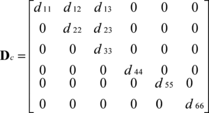
Dc is the stress-strain matrix of concrete. Before cracking of the concrete, it can be calculated as the general homogeneous body, the specific expression is
|
(3) |
In the equation(3),
|
(4) |
|
(5) |
|
(6) |
Among them, Ec is the elastic modulus of concrete, υ is Poisson's ratio. Since the relationship of stress and strain are non-linear, Ec varies with the state of stress.
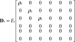
Stress-strain relationship of equivalent distribution steel, can be obtained by the following formula:
|
(7) |
Where, Es is the elasticity modulus of the steel; ρx, ρy, ρz stand for the reinforcement ratios along the x, y, z axis direction respectively.
3. Finite element calculation model
3.1 Joint model
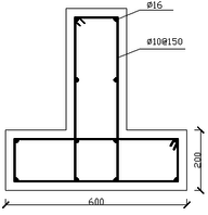
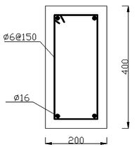
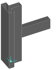
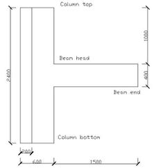
The calculation model in this paper is the frame joint of T-shaped column which is the side column of special-shaped column frame structure[2], as follows:
The height of the T-shaped column is 2.4m and the beam extends from the middle of the column for 1.5m. The limb length of T-shaped column is 600mm, and limb thickness is 200mm. The beam cross-section is of 400mm×200mm. The steel grade of longitudinal bars in both column and beam is HRB335 and that of stirrups is HPB300.The longitudinal bar diameter of column and beam is both 16mm . The stirrup diameter of column is 10mm, but that of the beam is 6mm. And the spacing of stirrups is all 150mm. Reinforcement placement can be seen above. The concrete strength level used for beam and column is both C30.
3.2 Mechanical properties of materials
Mechanical properties of C30 concrete are shown in the following table[16]:
| Strength
grade |
Elastic Modulus(MPa) | Poisson's ratio | Standard value of axial compressive strength (MPa) | Standard value of axial tensile strength (MPa) |
| C30 | 30000 | 0.2 | 20.1 | 2.01 |
The mechanical properties of HRB335 and HPB300 bars are as follows:
| Steel grades | Elastic Modulus(MPa) | Poisson's ratio | Standard value of yield strength (MPa) | Tangential modulus after yielding(MPa) |
| HRB335 | 200000 | 0.27 | 335 | 2000 |
| HPB300 | 210000 | 0.27 | 300 | 2000 |
3.3 The constitutive relationship of concrete
In order to determine the concrete uniaxial compression stress-strain relationship, the equations are selected as follows[16]:
|
(8) |
|
(9) |
among the equation (9),
|
(10) |
|
(11) |
|
(12) |
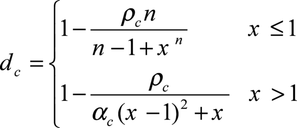
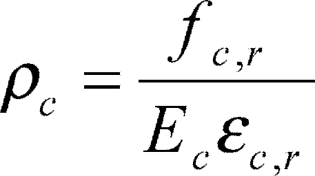
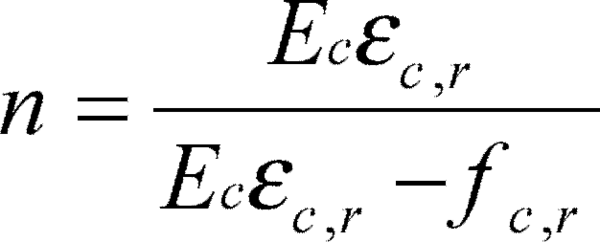
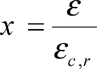
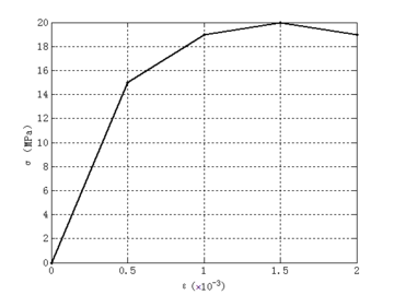
In the formulas above, dc is the uniaxial compressive damage evolution parameter of concrete; αc is the descending section reference value of uniaxial compressive stress-strain curve of concrete, taking 0.74 for C30 concrete in this paper; fc,r is the representative value of uniaxial compressive strength of concrete, taking 20.1N / mm2; εc,r is peak compressive strain of concrete corresponding to fc,r, taking 1.47×10⁻³. When the above values are put into the formula operation, the stress corresponding to a certain strain can be obtained, as shown in the following table:
| Strain ε | 0.0005 | 0.001 | 0.0015 | 0.002 |
| Stress σ(MPa) | 15 | 19 | 20 | 19 |
Drawing concrete four-fold line stress-strain relationship, as follows:
It can be seen that the constitutive relationship has a "softening" decline.
3.4 The establishment of the joint model
In this paper, the three-dimensional solid element SOLID65 , which is specially used to simulate the concrete and rock materials, is selected to establish the integral model of the joint. The Willam-Warnke five-parameter failure criterion and the distribution crack model are adopted in the element. When the stress combination reaches the failure surface, the element enters the crushing or cracking state[17][18].
The non-linear simulation in this paper obeys the von Mises yield criterion and multilinear isotropic hardening model[14][15].
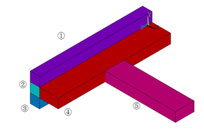
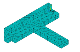
Model the joint and mesh it with tetrahedrons as below:
The reinforcement ratios of each part of the joint are as follows:
| Part ① | Part ② | Part ③ | Part ④ | Part ⑤ | |
| Direction X | 0.26 | 0.523 | 0.26 | 0.523 | 1.0048 |
| Direction Y | 0.523 | 0.523 | 0.523 | 0.13 | 0.0942 |
| Direction Z | 1.0048 | 2.0096 | 1.0048 | 1.0048 | 0.1884 |
4 Calculation results
4.1 Low-cycle repeated loading
Constrain the finite element nodes at the top and bottom of the column, and apply a uniform downward load of 858 KN on the top of the column. Apply a concentrated load in the vertical direction to the overhanging beam end, sequentially changing the direction of the load (up or down) in each load step, and gradually increase the concentrated load in the steps[19][20].
| Load step | Step 1 | Step 2 | Step 3 | Step 4 | Step 5 |
| Magnitude(KN) | 10 | 10 | 20 | 20 | 30 |
| Direction | Vertical down | Vertical up | Vertical down | Vertical up | Vertical down |
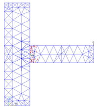
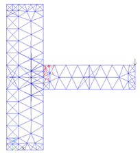
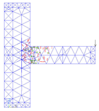
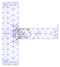
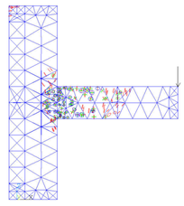
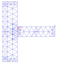
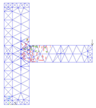
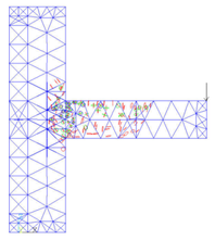
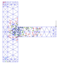
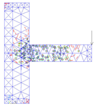
After the five load steps, the formation and development of cracks in the joint model can be got as follows:
(a)load step 1 (b)load step 2
(c)load step 3 (d)load step 4
(e)load step 5
It can be seen from the figure that after the first load step has been loaded, the cracks at the upper part of the beam head first appear due to the tensile stress. After the second load step is applied, there are cracks in the lower part of the beam head. In the third downward concentrated load step, the cracks develop to the column limb, the column part above the beam begins to crack because of the pulling force. The fourth load step is upward, the damage of the beam is aggravated, and the lower part of the column limb emerges the cracking phenomenon. With the fifth load step, fractures occur in the middle of the beam, the junction of beam and column limb is the most devastated, and the top of the column also fractures due to the uniform force.
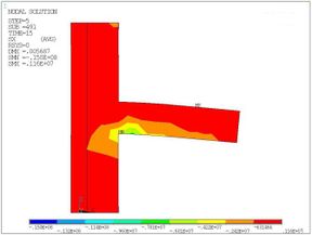
After the five load steps were loaded, the nephogram of major principal stress which is along the x-axis direction can be obtained as follows:
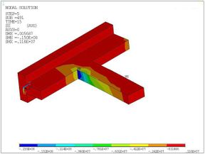
|
As shown in the figure, the stress on the pressure side of the beam is larger, and the stress on the beam head is the maximum. The stress at the column limb increases due to the extrusion effect, and the contour of stress develops obliquely. Different from the stress distribution, cracks appear on the tensile side of the beam and column limb, this is because the concrete tensile strength is much lower than its compressive strength.
4.2 Monotonic loading
As the repeated loading situation above, the top and bottom element nodes of column model are constrained and a uniform downward load of 858 KN is applied to the top of the column.
In monotonic loading situation, a vertically downward concentrated load is applied at the beam end and gradually increases until some elements of the model are destroyed[19][21].
Figure 10 shows the development of joint cracks with increasing load:
(a) 10KN (b) 20KN
(c) 30KN (d) 40KN
(e) 50KN
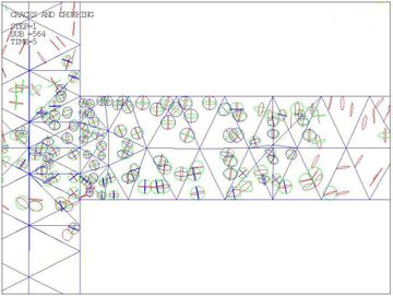
As in the figure, the cracks earliest appears at the beam head and then develop to the middle part of the beam and the column limb. When the load is added to 50KN, a element at beam head is completely damaged, and the failure mode of the damaged element is crushed.
Figure 11 is a partial magnification of the joint when the load force is 50KN, the rhombus appearing in a element means the element is completely destroyed:
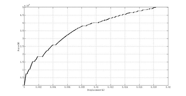
The relationship between the displacement of the beam end and the force under monotonic loading can be got as follows:
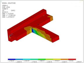
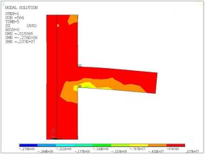
When the beam end is loaded to 50KN, the joint nephogram of major principal stress which is also along the x-axis direction can be acquired as follows:
(a) Isometric view (b) Side view
As shown, due to the stress concentration effect, the stress in the junction of beam and column limb is greater. And the stress in the compression side of beam head is the largest, which exceeds the compressive strength standard value of the concrete.
5 Conclusions
In this paper, by the elasto-plastic finite element analysis of a T-shaped column joint model, the crack development and the stress distribution of the joint under repeated and monotonic loading were observed, its failure mode was studied. The following conclusions can be drawn:
1. The use of integral finite element model, can make the analysis and calculation of model concise and efficient, easy to converge.
2. The four-fold line constitutive model of concrete adopted in this paper is suitable for the nonlinear simulation.
3. The failure mode of T-shaped column frame under repeated and monotonic loading is beam failure. The plastic hinge first appears at the beam head of the frame joint, and the two column limb intersection which is the core area of column is not damaged at all. The T-shaped column frame meets the "strong column weak beam"design principle.
References
[1] JGJ 149-2006. Technical specification for concrete structures with specially shaped columns[S]. Beijing: China Architecture & Building Press, 2006.
[2] S. C. YAN, et al. Comprehension and application of technical specification of concrete special-shaped column [M]. Beijing: China Architecture & Building Press, 2007.
[3] L. N. Lowes, N. Mitra. A beam-column joint model for simulating the earthquake response of reinforced concrete frames[R]. Pacific Earthquake Engineering Research Center, University of California at Berkeley, 2004.
[4]L. Li, J. B. Mander, R. P. Dhakal. Bidirectional cyclic loading experiment on a 3D beam-column joint designed for damage avoidance[J]. Journal of Structural Engineering, 2008 , 134 (11) :1733-1742.
[5] N. Hooda, J. Narwal, et al. An experimental investigation on structural behaviour of beam column joint[J]. International Journal of Innovative Technology & Exploring Engineering, 2013 , 3 (3):84-88.
[6] G. Somma, A. Pieretto, T. Rossetto, D. N. Grant. R.C. beam to column connection failure assessment and limit state design[J]. Materials & Structures , 2015 , 48 (4) :1-17.
[7] J. Marim.Design aids for L-shaped reinforced concrete Columns[J]. Journal of the American Concrete Institute, 1979, 76( 11): 1197-1216.
[8] L. N. RAMAMURTHY, T. A. H. KHAN. L-shaped column design for biaxial eccentric[J]. Journal of Structural Engineering, 1983, 109( 8) : 1903-1917.
[9] C. T. T. HSU. T-shaped reinforced concrete members under biaxial bending and axial compression [J]. ACI structural journal,1989,86( 4) : 460-468.
[10] Mallikarjuna, P. Mahadevappa. Computer-aided analysis of reinforced concrete columns subjected to axial compression and bending. Part II: T-shaped sections [J]. Computers & Structures, 1994 , 53 (6): 1317-1356.
[11] W. L. Cao, S. L. Gao, et al. Nonlinear analysis of T-shaped reinforced concrete columns[J]. World Information On Earthquake Engineering,1996,(1):32-37.
[12] D. Wang, C. K. HUANG, et al. Research on experiment and design method of specially-shaped columns under eccentric loading [J]. Journal of Building Structures, 2001, 22(5): 37-42.
[13]C. H. Chen, H. Gong, et al. Experimental study and nonlinear finite element analysis of concrete frame joint with T-shaped columns[J]. Industrial Construction , 2017, 47( 3):76-82,88.
[14] ANSYS, Inc. ANSYS structural analysis guide release 8.0[S]. SAP, IP Inc, 2000.
[15] J. J. JIANG, X. Z. Lu. Finite element analysis of concrete structures (Second edition) [M]. Beijing: Tsinghua University Press, 2013.
[16] GB50010-2010. Code for design of concrete structures [S]. Beijing: China Architecture & Building Press, 2010.
[17] Z. He, J. P. OU. Nonlinear analysis of reinforced concrete structures [M]. Harbin: Harbin Institute of Technology Press, 2007.
[18] F. LEGERON , P. PAULTRE , J. MAZAR . Damage mechanics modeling of nonlinear seismic behavior of concrete structures [J]. Journal of Structural Engineering - ASCE, 2005, 131(6):949-954.
[19] P. Jun, V. Mechtcherine. Behaviour of strain-hardening cement-based composites (SHCC) under monotonic and cyclic tensile loading: Part 1- Experimental investigations[J]. Cement & Concrete Composites, 2010 , 32 (10) :801-809
[20] H. Ma, X. Y. Sun, et al. Finite Element Analysis of Reinforced Concrete Beam-Column Joint under Low Cyclic Loading with Different Load Systems[J]. Applied Mechanics & Materials, 2013, 351-352 :351-354.
[21] I. N Doudoumis. Finite element modelling and investigation of the behaviour of elastic infilled frames under monotonic loading[J]. Engineering Structures, 2007 , 29 (6) :1004-1024.
Document information
Published on 08/02/19
Accepted on 13/03/18
Submitted on 10/12/17
Volume 35, Issue 1, 2019
DOI: 10.23967/j.rimni.2018.03.003
Licence: CC BY-NC-SA license
Share this document
Keywords
claim authorship
Are you one of the authors of this document?
