Abstract
We proposed a support system called the “Smart Partition System” for infill elements that integrate smart technologies according to the Open Building principles. The design requirements were collected from design practitioners. These design requirements consisted of both architectural and information subsystems. The Smart Partition System was composed of the following multiple levels of smartness: the foundation/core level with an embedded design knowledge in the support system and the utility level with a modular infill that integrate smart technologies. We constructed functional prototypes to demonstrate the feasibility of our proposed support system and some of the possibilities of the smart infill elements. Furthermore, the prototypes were evaluated by design practitioners. We compared our approach with current practices of smart building developments, and we also discussed some future prospects.
Keywords
Support system ; Smart house ; Open building ; Building renovation module ; Technology integration
1. Introduction
Integrating smart technologies into existing houses generally requires major renovations, which may be as time consuming and/or costly as building a new house. Given that a building may last for decades, the requirements to allow incremental integrations of smart technologies into buildings outweigh those of new smart houses. The open building principles provide a systematic approach for building constructions (Habraken, 1972 ). Two key concepts of the open building principles are supports and infills. The supports comprise all permanent, shared building services. An infill system is a carefully pre-packaged, integrated set of products and a custom prefabricated off-site for a given dwelling. By decomposing the construction of a building into various components that can be assembled through building products, the process enables incremental modifications and improvements of existing buildings.
We propose a support system for infill elements that integrate smart technologies. Considering that residential buildings are the largest building stock for improvement with new technologies in many Asian countries, the system is designed for the interior environment. Particularly, the system supports interior partitions of spaces, whereas the system itself is an infill of the overall structural support system of the building.
2. Supports and infills
Habraken (1972) has introduced the open building principles which divide a building into two levels: supports and infills. This division provides a systematic way of linking building elements and enables variations or customization according to residents׳ needs. The two levels are also decision-making levels, where residents can decide on the infills needed and the placements of these infills. To realize the open building policies, Habraken and Van Randen have developed the Matura infill system (Kendall and Teicher, 2000 ; Kendall, 1996 ). The Matura infill system consists of two elements: the matrix tile and the baseboard profile. The matrix tile system is based on a 10 cm×20 cm grid that accounts for the positioning of each component and its relationship to other elements. The baseboard profile is a track component that serves as the basis for interior partitions. These components provide design adaptability, fast on-site installation, and future changeability.
The curtain–wall construction of a building facade is one of the first innovations that allowed wall panels, which are infill elements, to be manufactured separately from the building structural framework, which is a support system. For example, the Blinkenlights project in Berlin, the BIX facade of Kunsthaus of Graz, and SPOTS in Berlin׳s Potsdamer Platz (Hall, 2006 ) are pioneering works of integrating smart technologies into the infill elements, i.e., curtain wall panels. To facilitate such kind of infill elements, the support system provides not only structural backing but also power supply and information communication. Furthermore, a building may contain various types of smart infill elements, as shown in previous developments (Chien, 2009 ), and the support system should provide flexibility to allow various types of infills.
3. System design
Integrating smart technologies into the living environment has been a topic of research since the late 1990s. Various projects such as the neural network house (Mozer, 1998 ), aware home (Kidd et al., 1999 ), and Easy Living (Shafer et al., 1998 ) have constructed prototypes or demonstrative houses. To operate these houses, a huge budget for maintenance and a knowledge on smart technologies are needed. Given that smart technologies are becoming affordable for the general public, architects and interior designers are receiving frequent requests from clients to integrate smart technologies, such as smart indoor environmental or lighting controls, when remodeling houses. We aim to develop an infill system that may assist in designing and deploying smart technologies for the clients of architects and interior designers.
3.1. Requirements analysis
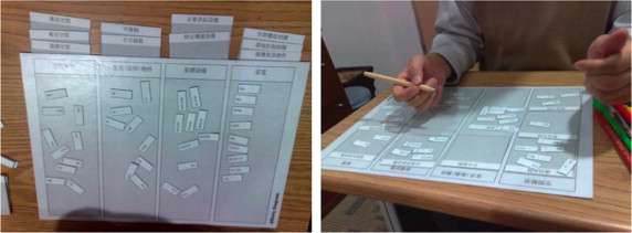
To understand the requirements of such kinds of systems, three design practitioners, one architect, and two interior designers are interviewed to collect possible kinds of infill elements or functional supports for interior partitioning walls. A set of keywords regarding activities, spaces, and interior elements (e.g., fixtures, furniture, and appliances) are extracted from the interviewed data. A researcher then works with each design practitioner to analyze the relationships among these keywords using the affinity diagramming method (Beyer and Holtzblatt, 1998 ) (Figure 1 ). The resulting affinity diagrams are consolidated into a relationship table of spaces and interior elements, which then sets the functional requirements of our proposed support system.
|
|
|
Figure 1. Affinity diagramming analysis. |
The following three types of spaces in a house have been identified by the design practitioners: common, designated, and service spaces. The common space is used by all house members, which includes the living room, dining room, and drawing room. The designated space includes the kitchen, study room, and bedroom; these spaces are mostly private spaces used by specific house members for specific functions. The service space includes the entrance hall, corridor, balcony, and bathroom. For the non-movable furniture and building elements (see last three rows in Table 1 ), cabinets are needed in all these spaces. For the movable furniture (see first six rows in Table 1 ), a folding screen (a free-standing partition) may be needed in the living room, dining room, and entrance hall.
| Common space | Designated space | Service space | ||||||||
|---|---|---|---|---|---|---|---|---|---|---|
| Living room | Drawing room | Dining room | Kitchen | Study room | Bedroom | Entrance hall | Corridor | Balcony | Bath room | |
| Chair | ⊙ | ◯ | ● | ● | ◯ | |||||
| Table | ⊙ | ⊙ | ● | ● | ◯ | |||||
| Bed | ● | |||||||||
| Sofa | ● | ● | ◯ | ⊙ | ◯ | |||||
| Folding screen | ⊙ | ◯ | ◯ | |||||||
| Window Curtain | ◯ | ◯ | ◯ | ⊙ | ||||||
| Cabinet | ⊙ | ⊙ | ⊙ | ⊙ | ● | ⊙ | ⊙ | ⊙ | ◯ | ◯ |
| Door | ⊙ | ◯ | ◯ | ◯ | ◯ | ● | ⊙ | ◯ | ⊙ | ◯ |
| Window | ● | ● | ◯ | ● | ⊙ | ● | ⊙ | ● | ||
The service equipment and infrastructure include the kitchen equipment, bathroom equipment, security, electricity, lighting, plumbing, and information equipment. Security and information equipment are needed in almost all the spaces (see Table 2 ). Appliances that are commonly used at home are those for communication, designated purposes, environmental control, and information and media. Communication appliances, such as a telephone set, are needed in almost all the spaces. Designated purpose appliances are required in specific spaces. Among three environmental control appliances, a lamp (movable lighting) is desired in all the spaces. For information and media appliances, a display screen is considered in the balcony (see Table 3 ).
| Common space | Designated space | Service space | ||||||||
|---|---|---|---|---|---|---|---|---|---|---|
| Living room | Drawing room | Dining room | Kitchen | Study room | Bedroom | Entrance hall | Corridor | Balcony | Bath room | |
| Kitchen equipment | ◯ | ● | ||||||||
| Bathroom equipment | ◯ | ● | ||||||||
| Security equipment | ◯ | ◯ | ◯ | ⊙ | ◯ | ⊙ | ◯ | ◯ | ||
| Electricity | ⊙ | ⊙ | ⊙ | ⊙ | ⊙ | ◯ | ⊙ | ⊙ | ⊙ | ⊙ |
| Lighting | ⊙ | ⊙ | ● | ⊙ | ● | ● | ⊙ | ⊙ | ⊙ | ● |
| Plumbing | ◯ | ● | ● | ● | ||||||
| Information equipment | ⊙ | ⊙ | ◯ | ⊙ | ● | ◯ | ⊙ | ◯ | ◯ | |
| Common space | Designated space | Service space | ||||||||
|---|---|---|---|---|---|---|---|---|---|---|
| Living room | Drawing room | Dining room | Kitchen | Study room | Bedroom | Entrance hall | Corridor | Balcony | Bath room | |
| Telephone | ● | ● | ◯ | ⊙ | ◯ | ◯ | ◯ | ◯ | ◯ | |
| Cell phone | ◯ | ⊙ | ||||||||
| Refrigerator | ⊙ | ● | ||||||||
| Oven | ⊙ | ● | ||||||||
| Washer | ● | ◯ | ||||||||
| Fan | ◯ | ⊙ | ◯ | ◯ | ||||||
| AC | ⊙ | ⊙ | ⊙ | ⊙ | ● | ⊙ | ◯ | |||
| Lamp | ⊙ | ⊙ | ⊙ | ◯ | ⊙ | ⊙ | ◯ | ⊙ | ◯ | ◯ |
| Display screen | ⊙ | ● | ⊙ | ⊙ | ◯ | ◯ | ||||
| Audio set | ● | ⊙ | ◯ | ◯ | ● | ◯ | ||||
| PC | ⊙ | ◯ | ● | ◯ | ||||||
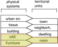
Considering these associations, to support these requirements, our support system needs to address the issues of interfacing with existing building structural components, provide infrastructure supports for information communication, and provide frameworks for flexible infills to serve various living styles and needs. According to the open building theory, the built environment can be modeled in five levels: urban street (city/district), tissue (urban block), building, infill, and furniture. These are physical systems built to support the daily living of people in various territories, such as towns, neighborhoods, dwellings, and rooms (Figure 2 ). From this aspect, our support system needs to address the room level territory supported by the physical infills and furniture.
|
|
|
Figure 2. Design focus (colored area) of our support system. (Redrawn from [ Habraken, 2002 ]). |
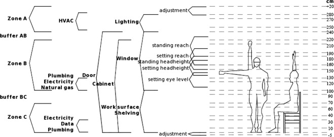
Considering these required associations, we defined the vertical infill zones into three parts (see Figure 3 ). Zone A comprises the space of 240 cm and higher; this space is beyond the standing reach of hands. Zone A is suitable for infills of environmental control appliances, such as air-conditioning and lighting units. Zone B is between 100 cm and 220 cm; this zone is the primary zone where living activities occur. The suitable infills for this space are cabinets, utility supplies (such as electric outlets and faucets), and working surfaces. Zone C is below 70 cm; this zone is easily reachable while sitting. The suitable infills for this space are low cabinets and utility supplies (such as network outlets). Between any two zones, buffer zones are provided to allow adjustments. These vertical infill zones are the basic references for the design of our infill system.
|
|
|
Figure 3. Vertical infill zones. |
3.2. Architectural system
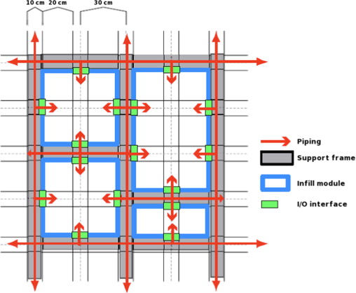
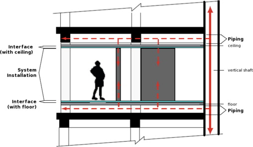
To provide the structural support, our support system is based on a 30-cm modular grid (see Figure 4 ). Each key supporting column is 10 cm wide and contains 5 cm interface strips to connect to the infill elements. The smallest clearance between two columns is 20 cm; however, a more feasible clearance between two columns is 50 cm. Electricity and information communication supports are provided to utilize the hollow part in each column. The system connects the existing building elements, floors, ceilings, and walls to the interface components (Figure 5 ).
|
|
|
Figure 4. Modular grid of the architectural system. |
|
|
|
Figure 5. The system in relation to the existing building elements. |
3.3. Information system
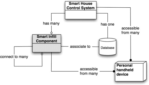
To support infill components with smart technologies, information communication is essential in the support system. With the architectural system providing hardware support for electricity and data network connection, we envisage our information system as a network of agents. The Smart House Control System is a special agent responsible for the overall information interface of the house. This system maintains the list of all Smart Infill Component agents and can relay information to each agent (Figure 6 ). Each Smart Infill Component is an agent that can connect to other agents, but operates autonomously with unique rules of interaction, sensors, and actuators. House members should be able to interact with any agent directly through handheld devices, such as a smart phone. All the data in this information system should be stored in a central database.
|
|
|
Figure 6. Information system object model. |
The communication protocols between the Smart House Control System and the Smart Infill Component agents should ideally support all existing standards of smart home networks that are proprietary (e.g., INSTEON® by SmartLabs, Inc. and LonWorks® by Echelon Corporation) or open (e.g., X-10 and KNX [EN 50090, ISO/IEC 14543]). In this research, we assume that the “translations between different protocols” are provided by another party and the service(s) may be integrated into the Smart House Control System or the “I/O interface” component of the architectural support system (see Figure 4 ). Our research team has been studying various configurations of the Smart House Control System agent and the Smart Infill Component agents. The Smart House Control System can be a special agent that organizes Smart Infill Component agents of the same type into a cellular automata network to implement the interaction rules among agents (Huang and Chien, 2008 ; Huang and Chien, 2009 ). However, given that the appropriateness of the configurations and the rules of interaction depend on the actual installations of infill components, we chose to maintain the information system as simple as possible.
3.4. Detail designs
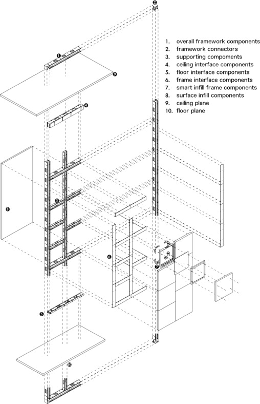
The detail designs of the physical support system concerns both the framework and interface components. The framework components comprise the overall framework of a partition wall; with preset openings (holes) on each element, the framework components allow the infill of smart infill components in various sizes. Figure 7 illustrates a composition of the framework components from the overall framework to the smart infills.
|
|
|
Figure 7. Composition of system components. |
With regard to the feasibility of our system, the detail designs are based on construction methods and materials that are popular in building and interior design applications. The overall framework components are lightweight H-steel columns with a thickness of 1.5 mm and a 100 mm×45 mm section. On the columns, preset openings of 10 cm×6 cm are placed every 30 cm for wiring and piping. For structural stability, horizontal supporting framework components, with the same dimensions as the vertical columns, are placed at least every 120 cm. Framework components for holding the smart infills are then connected to the overall framework and/or supporting framework components.
4. Prototype and evaluation
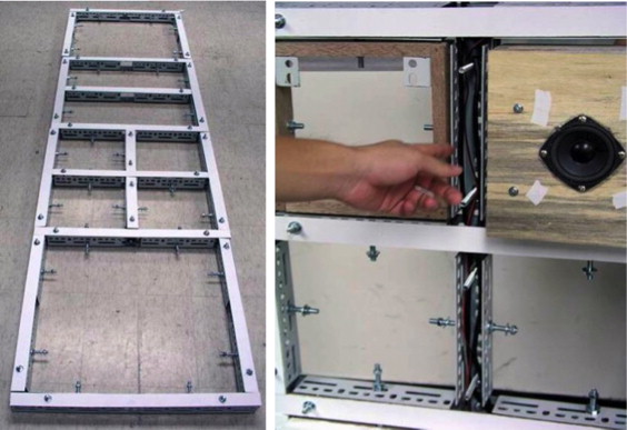
We constructed a functional prototype to demonstrate the feasibility of our proposed support system and some possibilities of the smart infill elements. The prototype was a partitioning wall that was 210 cm high and 120 cm wide (Figure 8 ). To demonstrate the electricity and information communication supports, we tested an information display infill that showed the occupancy status in the environment. To demonstrate the support of the kinetic infill elements, an adjustable (protruding) lighting infill was tested. In addition, to demonstrate the support of interaction between the occupants and the infill elements, an adjustable lighting infill was designed for the light intensity level to adjust according to the ambient lighting conditions.
|
|
|
Figure 8. Support and infill prototypes. |
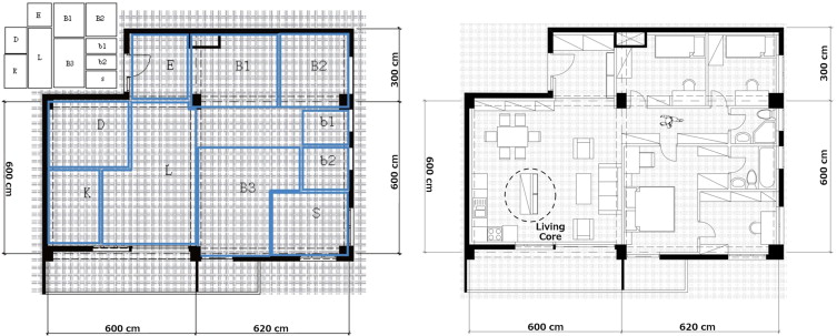
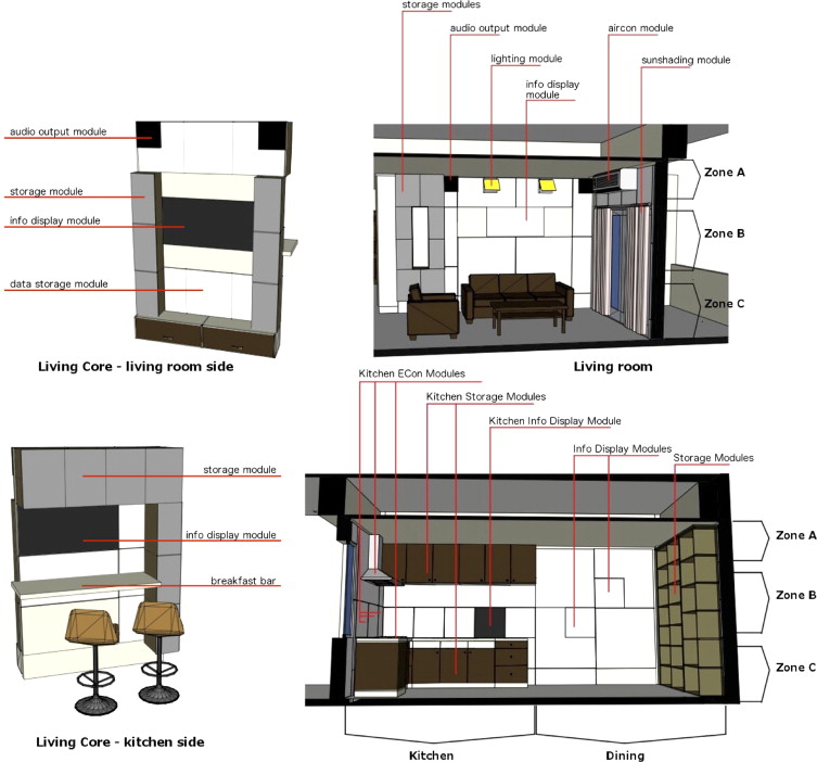
To validate the system, we conducted another round of studies with the design practitioners. We invited one of the three practitioners who participated in the previous interviews and asked this practitioner to complete an interior design using our system. The other two practitioners were provided with a documentation that showed the capabilities of our system, and these practitioners were asked to speculate the possible uses of the system, including the usage scenarios. The results showed that the design practitioners were able to use the support system for partitioning the spaces and positioning various infill functions (Figure 9 ). However, because of the very few smart household products known by the practitioners, the usage scenarios contained insufficient utilization of smart technologies that were beyond the currently available products (Figure 10 ).
|
|
|
Figure 9. Interior design produced by one practitioner based on our system. (Left: schematic layout. Right: detailed interior design.) |
|
|
|
Figure 10. Interior design with infill modules produced by the practitioners. |
5. Discussion
From the functional prototype and reviews with the design practitioners, we gained insights on the limitations of the current detail design, the smartness of the smart partition system, and the ways that our system can assist designers and their clients for co-creating smart environments.
5.1. Limitations of the current detail designs
The prototype, although the intended materials and construction methods were not used, demonstrated the appropriateness of the modular grid and the geometry. The prototype showed that the modular grid was able to accommodate various infill modules, including the information display, video sensor processing, shelving, audio speaker, and adjustable lighting modules, with sizes that ranged from 20 cm×20 cm to 20 cm×50 cm. However, to provide electricity and data connection for smart technologies, conduit space and openings on the framework components are highly critical. The current detail designs provide ample space for up to 4 smart infill modules from the same conduit through the overall framework components. We predicted that a 30 cm segment of the partition wall may install up to 8 smart infill modules, half of which the electricity and information wirings should be supplied from top (the ceiling region), whereas the other half have to be supplied from below (the floor region). With regard to piping spaces, the current detail designs work for supplying water pipes and HVAC cooling water, but these designs cannot handle pipes for wastewater, sewage, or air ducts. Even though our system design can potentially allow do-it-yourself installation styles and adjustments of smart infill modules without integrating the designs of wiring and piping connectors, this work should be performed by specialists, such as technicians or electricians.
5.2. The smartness of our support system
Our smart partition system exhibits smartness at two levels. At the infill level, the smart infill modules may integrate smart technologies to provide adequate services. At the system design level, we believe the design knowledge embedded into the system enables the advanced smartness. The flexibility through the built-in modularity of the system allows the adaptation and incremental improvement for the built environment to grow with the residents in that environment. From most of the early research prototypes of smart houses, e.g., (Kidd et al ., 1999 ; Mozer, 1998 ; Shafer et al ., 1998 ), to the state-of-the-art smart houses, smart technologies are optimized for special purposes. Considering the S-house (Chen and Chang, 2012 ) as an example, this house is a successful case of smart technologies in service of a sustainable design. The S-house has a central control unit with a carefully designed logic that considers multiple indoor temperature, air flow, air quality, occupancy sensors, and data from the outdoor micro-weather station to operate multiple air conditioners, sun shades, and windows for forced air cooling. Adding or upgrading smart technologies in the S-house will need a reprogramming of the central control unit of the house, or should any one of the sensors of the house fails, the central control unit of the house would not perform the appropriate controls. Contrary to the centralized intelligence of the S-house, our support system may provide a distributed intelligence. The smart infill modules may perform individually with possible integrated intelligence through cloud computing. The modular architectural system is another level of distributed intelligence that supports variability and adaptability.
5.3. Co-creating smart environments
The smart partition system establishes a framework for discussions and explorations among residents, designers, and technologists. The architectural system of this support system provides a modular grid that is similar to a game board for players (residents, designers, and/or technologists), where game pieces (infill components) can be placed or gaming strategies (various styles of smart living) can be explored. During the review of our system, the design practitioners were able to “play the game on some preset game board” to create a smart technology that integrated living rooms, dining rooms, and hallways. We predicted a game to be played by designers and their clients to create smart environments that fit the clients׳ needs. We also projected this game as facilitating the creation of new game pieces (new infill components) when designers or residents coordinate with technologists.
6. Conclusion
We proposed the smart partition system to integrate smart technologies into existing buildings. For designers, this system is a design support with dimensions, positions, and interfaces through modular coordination. We built a working prototype to demonstrate the possible implementations of the architectural elements and smart infill components. The smart infill components were implemented as independent agents that interact with the user control and the environment. However, these infill components did not interact with the user control and the environment. Moreover, we implemented other parts of the information system, namely, the smart house control system and the database.
We evaluated the system with three design practitioners. These design practitioners applied the design method and acknowledged the advantages of our system. Subcontractors and installers were not consulted directly during the evaluation because of their unavailability. However, in our local interior design and renovation application, interior designers also acted as contractors. The design practitioners who participated in our study evaluated from both design and construction aspects. Nevertheless, we aimed to explore further evaluations of our system through actual applications, similar to what the S-house (Chen and Chang, 2012 ) has done.
Our purpose of developing the support system was not to promote technology but to support the integration of new technology, should there be a need. Intille (2006) argued that the goal of investigating smart houses was to make people smarter. We were thinking along the same line as Intille (2006) . Furthermore, we believed that the essence of “smart” was “being right.” Therefore, we investigated on the right technology for specific needs. However, we do acknowledge that sometimes right technology means no technology.
Acknowledgments
The research is supported partly by the Minister of Science and Technology Taiwan (NSC 97–2420-H-006–039-KF3 ). The authors would like to thank the design practitioners of HCF Partners Architects Planners for participating in the requirement analysis and the evaluation phases of our research. A special recognition goes to the reviewers for their insightful comments for the improvement of the manuscript.
References
- Beyer and Holtzblatt, 1998 H. Beyer, K. Holtzblatt; Contextual Design: Defining Customer-Centered Systems; San Franscisco, Morgan Kaufmann Publishers (1998)
- Chen and Chang, 2012 S.-Y. Chen, S.-F. Chang; Complexity and contradiction in intelligent green architecture. The S-house as an example; Comput. Aided Des. Appl., 9 (2012), pp. 27–32
- Chien, 2009 Chien, S.-F., 2009. Smart building products. In: Proceedings of the 14th International Conference on Computer Aided Architectural Design Research in Asia, Yulin, Taiwan, pp. 695–703.
- Habraken, 2002 N. Habraken; The uses of levels; Open House Int., 27 (2002), pp. 9–20
- Habraken, 1972 N.J. Habraken; Supports: An Alternative To Mass Housing; The Architectural Press, London (1972)
- Hall, 2006 P. Hall; Living Skin: Architecture as Interface; Adobe Design Center, San Jose, CA (2006) 〈http://www.adobe.com/designcenter/Living_Skins.pdf〉
- Huang and Chien, 2008 Huang, Y.-P., Chien, S.-F., 2008. Smart intimate tiles: applying the concept of cellular automata on pressure sensing tiles in floor space indoor. In: Symposium for Emotion and Sensibility 2008 (ISES 2008), Seoul, Korea.
- Huang and Chien, 2009 Y.-P. Huang, S.-F. Chien; Composing smart houses; E. Dado, R. Beheshti, K. Zreik (Eds.), Innovations for Building and Construction, Europia Productions, Paris, France (2009), pp. 413–424
- Intille, 2006 Intille, S.S., 2006. The goal: smart people, not smart homes. In: Proceedings of ICOST2006: The International Conference on Smart Homes and Health Telematics, IOS Press, Amsterdam, pp. 3–6.
- Kendall and Teicher, 2000 S. Kendall, J. Teicher; Case studies; S. Kendall, J. Teicher (Eds.), Residential Open Building, E & FN Spon, London (2000), pp. 67–168
- Kendall, 1996 S.H. Kendall; Europe׳s ‘Matura Infill System’ quickly routes utilities for custom remodeling; Automated Builder Magazine, Oxnard, CA (1996)
- Kidd et al., 1999 C.D. Kidd, R. Orr, G.D. Abowd, C.G. Atkeson, I.A. Essa, B. MacIntyre, E. Mynatt, T.E. Starner, W. Newstetter; The aware home: a living laboratory for ubiquitous computing research. In: Proceedings of the second international workshop on cooperative buildings; Integrating Information, Organizations, and Architecture (1999), pp. 191–198
- Mozer, 1998 Mozer, M.C., 1998. The neural network house: An environment hat adapts to its inhabitants. In: Proceedings of the AAAI Spring Symposium on Intelligent Environments, pp. 110–114.
- Shafer et al., 1998 Shafer, S., Krumm, J., Brumitt, B., Meyers, B., Czerwinski, M., Robbins, D., 1998. The new EasyLiving project at microsoft research. In: Proceedings of the 1998 DARPA/NIST Smart Spaces Workshop, pp. 127–130.
Document information
Published on 12/05/17
Submitted on 12/05/17
Licence: Other
Share this document
Keywords
claim authorship
Are you one of the authors of this document?
