Abstract
This paper presents an enhanced coupled approach between the Finite Element Method (FEM) and the Discrete Element Method (DEM) in which an adaptative remeshing technique has been implemented. The remeshing technique is based on the computation of the Hessian of a selected nodal variable, i.e. the mesh is refined where the curvature of the variable field is greater. Once the Hessian is known, a metric tensor is defined node-wise that serves as input data for the remesher (MmgTools) that creates a new mesh. After remeshing, the mapping of the internal variables and the nodal values is performed and a regeneration of the discrete elements on the crack faces of the new mesh is carried out. Several examples of fracturing problems using the enhanced FEM-DEM formulation are presented. Accurate results in comparison with analytical and experimental solutions are obtained.
Keywords: Remeshing technique, coupled formulation, fracture mechanics, FEM-DEM, finite element method, discrete element method
1 Introduction
The modelling and simulation of the mechanical process of fracturing of materials and structures is one of the most challenging topics in computational mechanics. The laboratory predictions of the ultimate strength of materials and the detection/propagation of fractures is also a complex research topic due to their typical prompt or abrupt behaviour of crack, which difficulties the experimental analysis.
In this paper a novel coupled FEM-DEM formulation is presented. The method is based on previous works of the authors in coupling the FEM and DEM procedures [2][3]. The existing coupled FEM-DEM procedure is enhanced with an adaptive remeshing technique based on the Hessian of the distribution of a nodal variable of interest. Unlike in other fracture mechanics formulations [4][5][6][7][8][42][43], this methodology only uses the remeshing technique to improve the quality of the crack path. As shown in [2][3], the FEM-DEM formulation is capable of obtain accurate, consistent and mesh-independent results [2][3] due to the use of the super-convergent patch recovery technique [9], this avoids the need of stabilization of the stress field, as it is required in other alternatives [12][13][14].
The selection of a proper nodal variable whose Hessian is going to be computed is crucial in order to refine the mesh near the crack openings and not close to the Dirichlet or Newman boundaries.
The enhanced coupled FEM-DEM formulation here presented has been applied to a collection of benchmark problems. The numerical results presented in this paper prove the accuracy and correctness of the adaptive remeshing technique implemented.
2 State of the Art
2.1 State of the art in Fracture Mechanics
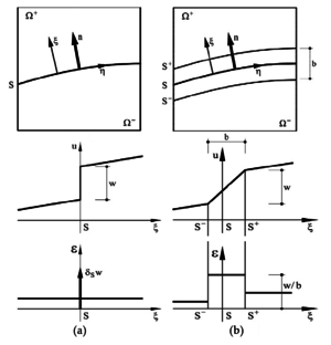
In the field of continuum mechanics, a fracture can be expressed mathematically as a discontinuity of the displacement field in a certain zone of the domain. In this way one must separate the body in two domains and and define the boundaries between them. This approach is called continuum strong discontinuity. Another option is to regularize the strong discontinuity by imposing a finite zone in which the displacement field is continuous and the strains are discontinuous but not infinite [14]. This technique is usually called continuum smeared approach (Fig. 1).
 ] ]
|
| Figure 1: Discontinuities in a continuum (a) strong discontinuity (b) continuum smeared approach. Image from [18] |
 ] ]
|
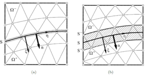
| Figure 2: Discontinuities in a discrete medium (a) strong discontinuity (b) discrete smeared approach. Image from [18] |
If one moves on from the continuum to the discretized problem, i.e. to the FEM, the discrete strong discontinuity technique was introduced by Clough [15], Ngo and Scordelis [16], Nilson [17]. It consists in separating the elements that have achieved a certain stress threshold by duplicating the affected nodes (Fig. 2). This methodology has the drawback that is inherently mesh dependent due to the fact that the propagation directions are the element boundaries.
In order to solve the previous limitation, a remeshed strong discontinuity procedure was introduced by Shephard[4] and Wawrzynek and Ingraffea [15] and improved by Bittencourt et al. [16]. In this case the mesh is refined in zones near the crack tip so the affected elements are split into smaller ones. This methodology overcomes part of the problems of the discrete strong discontinuity method but it has an additional computational cost regarding the remeshing procedure. Moreover, the remeshing tool needs to know the propagation direction of the crack, which is difficult to predict using conventional displacement-based formulations.
After analysing those technical issues, the previous formulation lead to the Extended Finite Element Method (XFEM) [19][20][21][22][23], which uses an enriched set of shape functions to interpolate the displacement field in the elements crossed by the crack.
As for the remeshing techniques, the embedding of the crack path requires to know the directions of the evolution of the crack and this is not accurately predicted in displacement-based formulations. In the XFEM an additional set of integration quadratures are required to properly integrate the split elements that, in normal conditions, have a singular stiffness. Additionally, these techniques usually require tracking techniques in order to preselect the elements that are going to be enriched [26].
Anther option is the so-called smeared crack approach. This model was initially proposed by Rashid [27] and it describes the crack path by a band of elements whose displacements field is continuous and its strain field discontinuous but bounded. Fig. 2b shows the finite elements band affected by the weak discontinuities. The smeared crack approach was very popular but after some years of its adoption Pietruszczak and Mroz [28] and Bazant and Oh [29] noticed that the fracture process is not only dependant on the fracture energy, but also on the characteristic length of the mesh analysed. This issue provokes that the finer the mesh is, the more brittle the behaviour is, which is an unacceptable inconsistency.
Despite the many different discrete weak discontinuities approaches, it was seen that the standard displacement-based formulations appeared to be inaccurate when dealing with the onset and propagation of fractures. This is due to the fact that on the crack tip the strains and stresses are not well predicted and, in general, the direction of the crack path is strongly dependant on the mesh orientation.
Regarding the enhanced or enriched finite element formulations, the multidimensional generalization of the displacement jump is not straight forward and it is usually accompanied by ill-conditioning problems. Additionally, since the mentioned enhancements are applied depending on the stress field of the previous time step and, taking into account that the standard displacement-based formulations do not guarantee the local convergence of the stress field, these methods often require the use of auxiliary crack tracking techniques.
Subsequently, other FEM formulations were developed in order to provide computational enhancements, such as mixed formulations. Mixed formulations are computationally more expensive than the standard ones since they require to solve multiple unknown fields. In addition, the finite elements have to satisfy the Inf-Sup condition [30][31] to ensure the stability of the solution. This condition is not easy to fullfil and several developments were introduced to mitigate this problem [32][33].
If one moves on from the methods based on the FEM to the DEM [36][37], the kind of problematic is intrinsically different. There are several approaches that discretize the continuum as a set of discrete elements (DE) (hereafter termed particles) attached by a bonding between them ruled by local or non-local constitutive laws [38][39]. However, the calibration of the local material parameters of the bonds between the particles is complex [40] and only under certain conditions behaves as a continuum. In addition, the large number of DE needed to solve practical problems discourages its use.
Bearing all this information in mind and trying to combine the best features of the FEM and the DEM, the FEM-DEM methodology was developed [2][3]. The continuum is initially represented with FE whose material behaviour is represented by an isotropic damage model. A smoothing procedure is used by computing the stresses at the element edges. When damage in a certain element achieves a maximum threshold, the element is removed from the mesh DE are placed at its nodes. The new DE avoid the indentation between the crack faces by the contact forces among them and these forces are transferred to the FE nodes as equivalent nodal forces.
2.2 State of the art in mesh refinement
2.2.1 Mesh generation
The early works of mesh generation by Zienkiewicz and Phillips[57] on the 1970s were based on the geometry boundary of the domain size and the required distribution of the element size. Since then many different technologies have been proposed, including mapping techniques and semi-automatic remeshing methods, where the domain has to be subdivided manually in a initial stage into simpler subdomains[49]. These methodologies depend on know-how from the user and are generally limited to structured meshes (quadrilaterals and hexahedra).
Alternatively to structured meshing algorithms, unstructured meshing techniques have been extensively developed for simplex element geometries: triangles in 2D and tetrahedra 3D. These techniques are based mainly in three algorithms[1]:
- Delaunay triangulation methods[50].
- The advancing front method[51].
- Tree methods: quadtrees for 2D and octrees for 3D cases[52].
2.2.2 Adaptive finite element refinement techniques
Mesh adaption is widely used in numerical simulations to improve the accuracy of the solutions, as well as to capture the behaviour of physical phenomena[60]. This technique allows to reduce considerably the computational cost, associated with a reduction of degrees of freedom (DoF from now on), while yielding an accurate solution[67].
Adaptive mesh refinement allows to compute complex problems with good results in 3D without requiring the initial remeshing during pre-processing step, which can be a time consuming and error-prone[1] task. Additionally, adapting the computation during the simulation, avoids the creation of an initial mesh that fits all the problem evolution, which can be a priori not known.
The mesh refinement process depends on the previous numerical results[1]. These methodologies were introduced originally by Babuška and Rheinboldt[53][54] in the late 1970s.
One of the most popular mesh remeshing strategies is based on the recovery by equilibrium of patches (REP) techniques. A widely used approach based on REP is the Superconvergent Patch Recovery (SPR) technique proposed by Zienkiewicz and Zhu [9]. The methodologies based on REP are not the only ones available to measure the error. Zienkiewicz and Zhu proposed other techniques by using different recovery methods[10]. Recently, techniques based on the Hessian of a solution field have been developed[66]. This requires that the variable to be used as error estimation has to be twice continuously differentiable. This methodology has the advantage of giving a proper measure in order to create anisotropic meshes, which reduces the number of new elements necessary.
3 Coupled FEM-DEM Formulation
The coupled FEM-DEM formulation was developed by Zárate and Oñate[2] as an effective procedure for predicting the onset and propagation of cracks in concrete and rocks. Zárate, Cornejo and Oñate[3] extended the formulation to 3D problems.
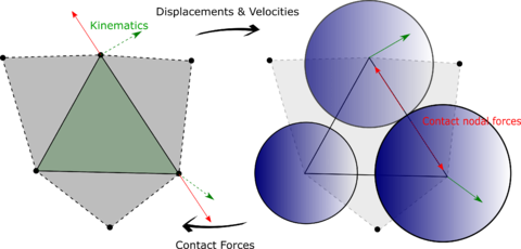
Initially the continuum is modelled with simplex FE (3-noded triangles in 2D and 4-noded tetrahedra in 3D). The FE solution is obtained by reaching the dynamic equilibrium via an implicit transient dynamic solution scheme. An isotropic damage constitutive law is chosen in order to verify failure at the edges of the FE (using the SPR technique [9]). Once one of the failure modes of the FE is achieved, this FE is removed from the mesh and DE are placed at the nodes of the removed FE (see Fig. 3 and [2][3]).
Some important aspects inherent to the FEM-DEM formulation guarantee the good results obtained, such as a smoothed stress field, mass conservation and the use of a simple algorithm to ensure the post-fracture contact between the fractured edge and the adjacent FE and DE in the mesh[2][3].
|
| Figure 3: DE generation after removing a FE |
3.1 FEM formulation
The predictive stress tensor on all the elements of the mesh is initially computed, as:
|
|
(1) |
where is the elastic constitutive tensor and the strain tensor.
Once the predictive stresses at the integration points of all the elements of the mesh are computed, the smoothed stress field is evaluated at the edges of the FE. The smoothing procedure is based on the average stress between the current element and the neighbour one sharing an edge, i.e.
|
|
(2) |
Next, the constitutive equation is integrated at the edges. An isotropic damage model is used if the stress state is outside the yield surface , i.e.
|
|
(3) |
where is the uniaxial stress that is computed according to different yield surfaces and is the mechanical threshold that is related to the yield strength. In the examples performed in this work we have used the Rankine and Modified Mohr-Coulomb[41] yield surfaces. Once the initial threshold is achieved it has to be updated according to the maximum historical stress state.
The isotropic damage constitutive model is written as:
|
|
(4) |
where is the damage parameter that takes into account material degradation as well as the irreversibility of the constitutive model. As far as the computation of damage is concerned, we have used the exponential softening law[69]:
|
|
(5) |
where the parameter is determined from the energy dissipated in an uniaxial tension test as[69]
|
|
(6) |
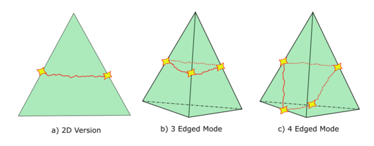
where is the tensile strength, is the specific fracture energy per unit area (taken as a material property) and is the characteristic length of the element. In this way one can compute the damage at the midpoint of the element edges. Next, the damage of the whole element is be evaluated. By analysing all the fracture modes that can occur, the damage of the element corresponding to the mode with less energy is computed (Fig. 4). In 2D problem one can use average the two maximum values at the element edges, as:
|
|
(7) |
|
| Figure 4: Different fracture modes in 2D and 3D element geometries |
3.2 Tangent constitutive tensor approximations
The FEM solution is obtained via an implicit transient dynamic solution scheme. Thus, the tangent constitutive matrix is required at each iteration of the loading step. For this purpose, several numerical techniques have been developed and adapted to the FEM-DEM formulation.
The most robust but slower option is to use the secant constitutive tensor , computed as a function of the initial constitutive tensor and the damage :
|
|
(8) |
Another alternative is based on the derivatives approximation via finite differences, i.e. the tangent constitutive tensor relationship can be expressed as . A column of the tangent constitutive tensor is defined as [34]:
|
|
(9) |
An approximation of the tangent constitutive tensor can be obtained by defining small perturbations of the strain tensor in order to obtain stress tensor increments . This can be done in several ways, as stated below (depending on the finite difference scheme):
|
|
(10) |
where is a zero vector except for the th component whose value is the strain perturbation .
The most general option consists in perturbing the displacement field of the FEM solution [35]. This method is appropriate for small and large strain computations (the strain perturbation method is limited to small strains) and for any kind of constitutive model. In this way, the approximation of the tangent stiffness matrix can be computed as:
|
|
(11) |
Where is the th column of the tangent stiffness matrix, is the displacement increment of that node in the previous time step, is the internal force vector that depends of the displacement field and is a small constant computed as:
|
|
(12) |
being the computer precision. Note that the components of the vector are null except for the th component whose value is .
3.3 DEM formulation
The DEM methodology used in the FEM-DEM formulation implemented in this work is based on the work of Casas et al [44], Oñate et al [38] and Thornton et al. [45].
The motion of the DE is computed by solving the dynamic equilibrium of forces at the center of each particle using an explicit dynamic solution scheme. A sub-stepping procedure has been implemented in order to combine the DEM explicit calculations with the implicit solution scheme[2][3] for the FEM.
A spring-dashpot type soft-sphere approach for the contact between spheres has been selected. Considering two contacting spheres, whose centres are and , the normal vector that connects the centers of the spheres can be computed as follows:
|
|
(13) |
The normal indentation between the discrete particles is computed as:
|
|
(14) |
where are the radii of the particles. The total contact force between two particles is defined as the sum of a normal and a tangential force:
|
|
(15) |
The normal contact force is obtained as a combination of an elastic and a viscous contribution:
|
|
(16) |
Where the elastic part can be computed as:
|
|
(17) |
where . The corresponding viscous damping contribution is modelled as:
|
|
(18) |
For particle-particle contact the constant can be expressed as:
|
|
(19) |
being and a viscous damping coefficient.
On the other hand, the tangential force is computed as:
|
|
(20) |
where the directions and are based on the kinematics during tangential deformation [40].
The elastic tangential contribution is obtained by:
|
|
(21) |
and the tangential viscous contribution as
|
|
(22) |
with
|
|
(23) |
where and .
3.4 Coupling between the FEM and the DEM
Once the damage parameter for an individual element computed by Eq. (7) reaches a maximum threshold, the damaged element is removed from the FE mesh and a set of DE are placed at the nodes of the removed element (Fig. 3, [2][3]).Following this, the displacements and velocities of the element nodes are transferred to the DE. The next step is the integration of the dynamic equations of motion of the DE using an explicit scheme using a substepping procedure.
After performing a contact search among all the DE, the contact forces at each DE (as defined in Section 3.3) are computed. Once these contact forces are known, this information is transferred to the FEM mesh as an equivalent nodal force (Fig. 3) whose objective is to prevent indentation between the crack faces. More information about the time integration of the dynamic equations for the DEM and the FEM is given in [2].
4 Hessian Based Remeshing Technique
In this section we analyse on detail the techniques considered for remeshing. We introduce first the concepts of metrics (Section 4.1) and general Hessian based error measures (Section 4). Then we present the transfer operators for the damage parameter.
4.1 Metric based remeshing
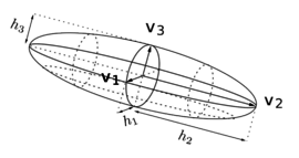
In order to understand the concept involving the Hessian metric[58], we first introduce the concept of metric. Then, we will show the intersection operations needed in case than more that one metric is taken into consideration.
|
|
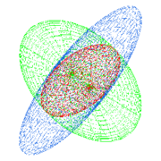
| (a) Metric analogy | (b) Intersection |
| Figure 5: Metric analogies. Images from [58] | |
4.1.1 Concept of metric
The notion of length in a metric space is related to the notion of metric[67] and therefore to an adequate definition of the scalar product in the vector space considered. We define a metric tensor at a point , respect an element from a mesh , represented by a matrix () defined symmetric positive and not degenerated. In 3D, the following definition of (24) is used, which can be assimilated to the analogy of an ellipsoid (Fig. fig:analogy).
|
|
(24) |
Tensor can be diagonalized because it is symmetrical. Then, can be written as , where and are the matrix of the eigenvectors and eigenvalues of , respectively.
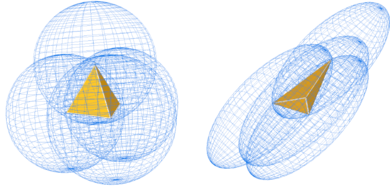
Fig. 6 illustrates the effect of the metric on the mesh. The tetrahedra presented gets sketched accordingly to the metric computed at each node, represented with ellipsoids (Figure fig:analogy).
|
| Figure 6: Effects of the metric on a tetrahedra |
4.1.2 Metric intersection
In the case that several metrics are specified at the same point of the mesh (for example if we want to use various nodal variables whose Hessians return different metrics) one have to define a procedure of intersection of all these metrics into one.
To define the intersection of two metrics, we use the fact that a metric tensor is represented geometrically by an ellipse (in 2D) or an ellipsoid (in 3D). The metric intersection consists then in keeping the most restrictive size constraint in all the directions imposed by this set of metrics[58] (Fig. fig:intersection).
The simultaneous reduction enables us to find a common basis (, , ) such that and are congruent to a diagonal matrix. In this basis we can define a new tensor , whose expresion is:
|
|
(25.a) |
can be diagonalized in because it is symmetrical in the metric . The base in question is given by the normalized eigenvectors of that we denote , and (they form a base because is diagonalisable) . The eigenvalues of and are found in this base using the Rayleigh quotient:
|
|
(25.b) |
Considering be the matrix the columns of which are the eigenvectors of (common basis) one can obtain
|
|
(25.c) |
The metric intersection can be computed as:
|
|
(25.d) |
4.2 Hessian based error measure
Before introducing the theory involving the Hessian based metric, we summarize the following properties[67]:
- The analysis and results obtained by this methodology are not asymptotic. This means that the size of the mesh does not tend to zero, avoiding potential errors, like the collapse of the mesh at certain points.
- The metric is based in the Hessian of the solution.
- The metric is anisotropic.
- It is independent of the nature of the operator, so it can be used with any type of equation.
4.2.1 Theory
We compute the Hessian[66] matrix of a scalar variable as
|
|
(26) |
Once the Hessian matrix has been computed we compute the corresponding anisotropic metric by [58].
|
|
(27.a) |
Being the eigenvalues of H and the error threshold and a constant ratio of a mesh constant. The interpolation ratio has been taken as . On the other hand can be taken as and for 2D and 3D cases, respectively. For an isotropic mesh the metric will be,
|
|
(27.b) |
For an anisotropic mesh we have
|
|
(27.c) |
4.2.2 Example
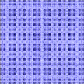
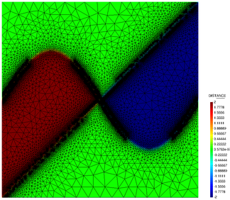
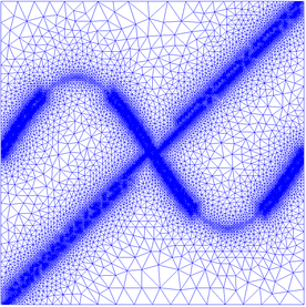
The objective is to remesh the structured mesh of Fig. 7 according to the Hessian of the nodal variable (objective function) defined in Eq. (28). The original mesh has 40000 structured elements. Our objective is to obtain an unstructured mesh where the smaller elements will be in the vicinity of the objective function.
|
| Figure 7: Initial mesh |
The nodal variable values are computed according to:
|
|
(28) |
The results obtained are depicted in Fig. 8b, using a mesh of 15000 elements. The smaller elements are placed around the shape displayed in Fig. 8a showing also the nodal value of the funcion defined in Eq. (28).
|
|
| (a) Nodal values of Eq. (28) | (b) Remeshed mesh |
| Figure 8: Nodal values of the remeshed mesh for the error function from Eq. (28) | |
4.3 Hessian nodal indicator
In order to optimize the remeshing technique and refine the elements close to the crack opening we define a proper nodal variable whose Hessian is computed. Initially, the nodal extrapolation of the predictive Cauchy's stress tensor was selected but the meshes generated with this indicator were suboptimal, as it refines the zones near the boundary conditions where, in general, there is no interest. In the end, a normalized energetic nodal variable indicator was selected. The expression of the mesh refinement indicator is:
|
|
(29) |
where is the material density, is the damage internal variable, and are the regularized fracture energies in tension and compression, respectively and is a tension indicator computed as:
|
|
(30) |
being the principal components of the stress tensor. The mesh refinement indicator can be interpreted as the energy dissipated, normalized with the total energy available.
4.4 Internal variables interpolation
The internal variables information has to be recovered in the refined mesh in order to work with constitutive models that depend on historical values, such as the damage model used in this work. Fig. 9 shows graphically how each one of the transfer operators work[56] (all of them are available in Kratos[48]).
 ] ]
|
| Figure 9: Transfer operators: a) Closest Point Transfer b) Shape Function Projection Transfer c) Least-Square Projection Transfer . Image from [56] |
- CPT: Closest Point Transfer. (a). It takes the value from the closest point. It provides acceptable results at low cost.
- SFT: Shape Function Projection transfer. (b). It interpolates the values using the standard FEM shape functions. It leads to an artificial damage diffusion, but preserves the original shape of the damage profile.
- LST: Least-Square Projection transfer. (c). It considers a least-square transfer across the closest points. Probably it is the most accurate technique but also the most expensive from a computational point of view.
In our simulations we have used the CPT technique.
5 Implemented Algorithm
The FEM-DEM formulation presented can be summarized in the algorithm below.
|
|
Algorithm. 1 Enhanced FEM-DEM algorithm |
6 Numerical Examples
Several examples are presented in order to show the accurate results and good representation of the fracture paths obtained with the enhanced FEM-DEM formulation developed in this work. The first example is the well-known four point bending test whose fracture path is theoretically known and the force-displacement evolution has been compared with the results from [46]. The second example is a tensile test whose analytical solution is trivial, so it is very useful in order to validate the formulation. Finally, a three-point bending test on skew notched beam has been performed. The FEM-DEM results have been compared with those obtained by Cervera et al. [47]. For the 2D examples (Section 6.1) we have used 3-noded triangles. The 3D problems have been solved using 4-noded linear tetraedra.
6.1 Four-Point Bending Beam
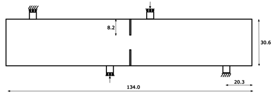
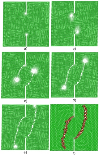
This example is a plane stress four point supported beam with a double notch. In the two central supports a vertical displacement is imposed whereas in the exterior supports only the vertical displacement is enforced to be zero (one of them must be clamped, as depicted in Fig. 10). The dimensions of the beam are 134 x 30.6 x 30 cm. The yield surface used is the Modified Mohr-Coulomb[41]. The material properties used are: E = 30 GPa, = 0.2, = 0.3 m, = 2 MPa, = 100 and the friction angle = . The initial FE mesh is displayed in Fig. 11. Fig. 12 shows that the remeshing technique and the Hessian variable indicator defined in the Section 4 are performing excellently as far as capturing the crack path is concerned. Another interesting feature is that the number of FE does not increase indefinitely. Fig. 12 shows that the number of FE in the mesh increases with respect to the initial coarse mesh but during the calculation is bounded up to a reasonable value (even decreasing at the end of the simulation) so the computational cost is balanced.
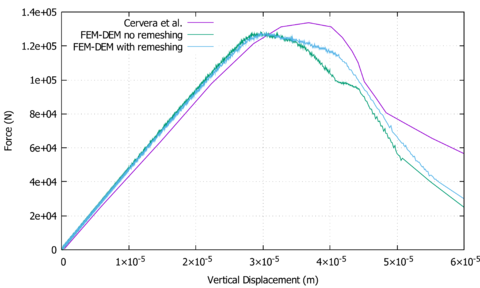
Quantitatively, the force-displacement evolution in one of the central supports is depicted in Fig. 14. In this figure the results from [46] and the ones from the FEM-DEM formulation, with or without remeshing, are compared, showing a good agreement between them.
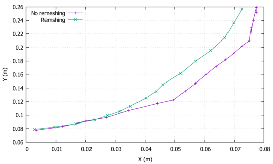
Additionally, the comparison between the crack paths using the remeshing technique and the standard FEM-DEM formulation is depicted in Fig. 15. As one can see, the quality of the crack path is improved with the inclusion of the remeshing technique but, as the non-remeshed solution uses a coarser mesh, the CPU is about 14 min whereas the remeshed solution increases the CPU time up to 45 min. The main advantage of this methodology lies in obtaining great quality crack paths without the requirement of a very fine original mesh.
|
| Figure 10: Geometry and boundary conditions of the four point bending test (units in cm) |

|
| Figure 11: Initial FE mesh used in the calculation (2912 3-noded triangles elements and 1573 nodes) |
|
| Figure 12: FE meshes during calculation (a) 5388 FE, b) 6276 FE, c) 8985 FE, d) 8188 FE, e) 6252 FE and f) Final result without remeshing technique |
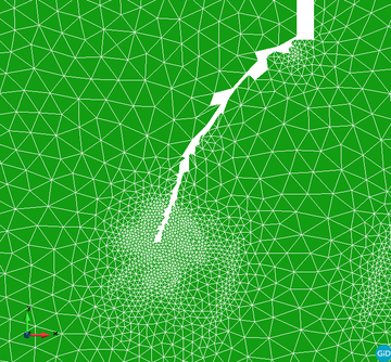
|
| Figure 13: Zoom of the refined FEM mesh in Fig. 12b |
|
| Figure 14: Force-displacement evolution in the four point bending test at one of the inner supports |
|
| Figure 15: Crack paths comparison between the remeshed and non-remeshed solutions |
6.2 Tensile Test
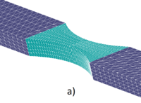
In this example a conventional 3D tensile test has been reproduced. The geometry of the sample is depicted in Fig. 16 with a thickness equal to 0.2 m. The left end is clamped and the right one has a monotonic imposed displacement. The Modified Mohr-Coulomb yield surface has been used. The material parameters are: E = 35 GPa, = 0.2, = 1.5 MPa, = 30 and the friction angle = .
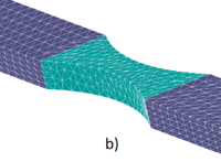
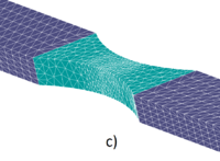
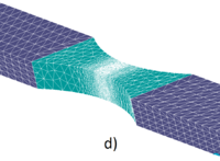
Fig. 17 shows that the mesh refinement is concentrated at the center zone, where all the energy dissipation is taking place due to the damage in the necking zone. The force-displacement evolution at one of the ends of the sample is depicted in Fig. 18. The results are in good agreement with the analytical expected solution ().
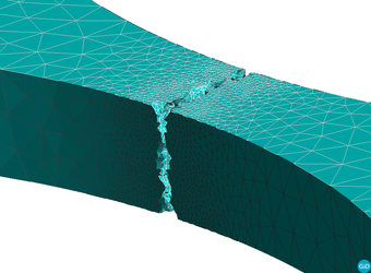
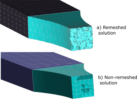
In Fig. 19 the final fracture of the sample is depicted. As expected, fracture occurs at the center of the necking. It is important to notice that the remeshing technique improves the quality of the cracking path (see the comparison in Fig. 20) but quantitatively is always consistent (Fig. 18), even when using coarse meshes.

|
| Figure 16: Tensile test geometry (units in m) |
|
|
|
|
| Figure 17: Tensile test FE meshes during the remeshed FEM-DEM calculation using 4-noded tetrahedra (a) 12000 FE, b) 8248 FE, c) 14092 FE and d) 70749 FE | |

|
| Figure 18: Force-displacement evolution for the tensile test at one of the ends of the sample |
|
| Figure 19: Tensile test fracture in the sample at the end of the calculation |
|
| Figure 20: Tensile test comparison of the crack pattern between the solution with (a) or without (b) the remeshing technique |
6.3 Three-Point Bending Skew Notched Beam
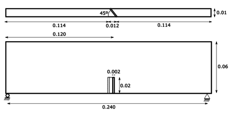
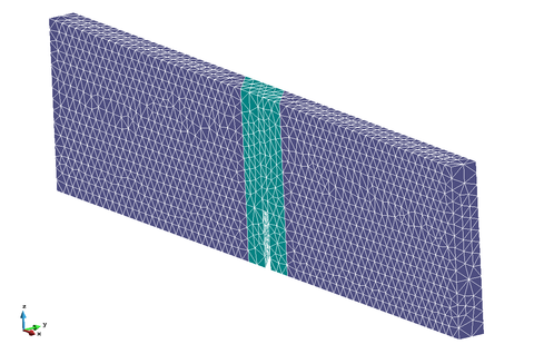
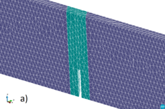
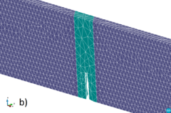
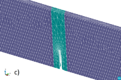
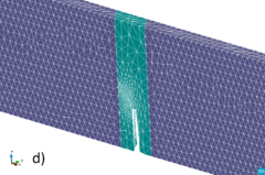
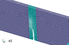
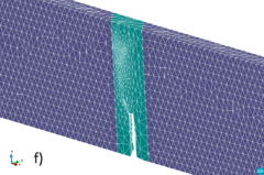
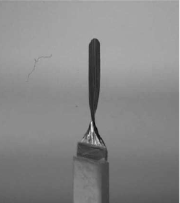
In this section, a skew notched beam subjected to three-point bending is analysed. The same problem was studied by Cervera et al. [47]. The original experiment was performed by Buchholz et al. [68] using Plexiglass in order to identify the fracture path along the sample. The geometry of the sample is shown in Fig. 21 in which the deviation of the notch can be seen. The Rankine yield surface was used in this test as in [47]. The material parameters are: E = 28 GPa, = 0.38, = 40 MPa and = 3000 . The analysed problem is symmetric with respect to the notch and it fractures under a mixed Mode I and Mode III. Initially the crack path twists around the vertical axis until it is oriented perpendicular to the longitudinal direction of the beam. The initial mesh is depicted in Fig. 22. The FE meshes generated during the calculation using the remeshing technique can be analysed in Fig. 23. As it can be seen, the remeshing technique refines the elements near the notch due to the high dissipation that takes place in these zones. As the crack propagates, the remeshing follows the expected path by refining the front of the fracture at each remeshing step.
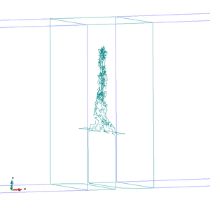
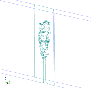
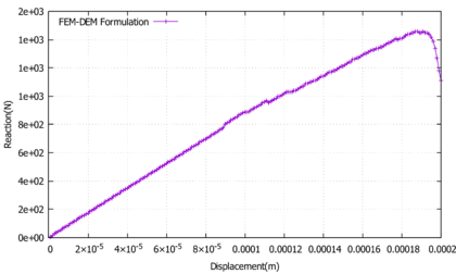
If one compares the results obtained with the simulation (Fig. 24) with the experimental results (Fig. 25) it is clear that the crack path follows the pattern obtained by the experiment accurately. As stated before, the solution obtained is skew-symmetrical. Also, the crack surface is perpendicular to the longitudinal axis at the end of the propagation as expected. The force-displacement evolution can be seen in Fig. 26. No numerical results regarding the force-displacement evolution was provided by the authors of this experiment.
|
| Figure 21: Three point bending skew notched beam geometry (units in m) |
|
| Figure 22: Three point bending skew notched beam initial FE mesh (15546 4-noded tetrahedra) |
|
|
|
|
|
|
| Figure 23: Adaptive FE meshes of 4-noded tetrahedra during calculation a) 15546 FE, b) 14436 FE, c) 16707 FE, d) 25811 FE, e) 27478 FE and f) 29738 FE | |
|
|
| Figure 24: 3-Point bending beam test skew fracture path obtained with the simulation | |
 ] ]
|
| Figure 25: 3-Point bending skew beam experimental results with Plexiglass [68] |
|
| Figure 26: 3-Point bending skew beam force-displacement evolution at the center of the beam |
7 Conclusions
In this work a coupled FEM-DEM formulation enhanced with a novel adaptive remeshing technique has been presented. The proposed methodology has demonstrated a good performance: quantitatively, when comparing the force displacement curves obtained with the analytical ones, and qualitatively when analysing the crack paths obtained versus the expected or experimental results.
The standard FEM-DEM is an accurate numerical procedure due to its intrinsic mesh-independence and consistency features[2][3]. However, the adaptive remeshing technique here presented improves considerably the crack path geometry obtained and optimizes the calculation cost, because it only refines the zones of interest, where the non-linear dissipation takes place.
Regarding the remeshing technique, the Hessian based methodology combined with the nodal variable indicator developed (normalized free energy) has behaved very well in all the examples performed, capturing the zones of interest where the mesh needs to be refined.
In conclusion the FEM-DEM formulation, enhanced with the adaptive remeshing technique presented, is suitable for simulating complex fracture mechanics problems at an affordable computational cost. For instance, the four point bending test was run in 50 min, the tensile test in 9 hours and the three point bending test in 4 hours. All the tests were carried out in a personal computer (CPU: Intel Core i7-8700, RAM: 16 GB DDR4) using 12 threads.
8 Appendix
8.1 Kratos multiphysics

|
| Figure 27: Kratos Multiphysics logo. https://github.com/KratosMultiphysics/Kratos |
The FEM-DEM formulation presented has been implemented in the Kratos multi-physics framework [48] that has been specially designed for helping the development of multi-disciplinary finite element programs. We can summarize the following features:
- Kernel: The kernel and application approach is used to reduce the possible conflicts arising between developers of different fields.
- Object oriented: The modular design, hierarchy and abstraction of these approaches fits to the generality, flexibility and re-usability required for the current and future challenges in numerical methods. The main code is developed in C++ and the Python language is used for scripting
- Open source: The BSD (Berkeley Software Distribution) licence allows to use and distribute the existing code without any restriction, but with the possibility to develop new parts of the code on an open or close basis depending on the developers. Additionally Kratos can be freely used.
8.2 Mmg library
8.2.1 What is Mmg and how does it work?

|
| Figure 28: Mmg logo. Image from Mmg web |
Mmg is an open source software for anisotropic automatic remeshing for unstructured meshes based on Delaunay triangulations. It is licenced under a LGPL license and it has been integrated in Kratos[48] via the mmg_process.h in the MeshingApplication. It provides three applications and four libraries:
- The
mmg2dapplication and thelibmmg2dlibrary: adaptation and optimization of a two-dimensional triangulation and generation of a triangulation from a set of points or from given boundary edges. - The
mmgsapplication and thelibmmgslibrary: adaptation and optimization of a surface triangulation and isovalue discretization. - The
mmg3dapplication and thelibmmg3dlibrary: adaptation and optimization of a tetrahedral mesh and implicit domain meshing. - The
libmmglibrary gathering thelibmmg2d,libmmgsandlibmmg3dlibraries.
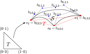
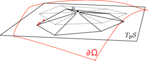
The Mmg remeshing process modifies the mesh[63][64] iteratively until it is in agreement with the prescribed sizes on the idealized (Fig. 29) contour (and directions in case of anisotropic mesh). The software reads the mesh and the metric, then the mesh is modified using local mesh modifications of which an intersection procedure based on anisotropic Delaunay kernel.
|
|
| (a) A piece of parametric Bézier cubic surface, associated to triangle T | (b) The resulting configuration of the vertex relocation procedure |
| Figure 29: Mmg idealized geometry. Image from [64] | |
We can resume the remeshing algorithm in the following steps:
- Mmg tries to have a good approximation of the surface (with respect to the Hausdorff parameter).
- It remeshes according to a geometric criterion. Mmg scans the surface tetrahedra and splits the tetrahedra using predefined patterns if the Hausdorff distance[65] between the surface triangle of the tetrahedra and its curve representation does not respect the Hausdorff parameter.
- The library scans again the surface tetrahedra and collapse all the edges at a Hausdorff distance smaller than a threshold defined in terms of the Hausdorff parameter.
- Next it intersects the provided metric and a surface metric computed at each point from the Hausdorff parameter and the curvature tensor at the point.
- Then Mmg smooths the metric to respect the gradation parameter. The metrics are iteratively propagated until the respect of the gradation everywhere.
- Next it remeshes the surface tetrahedra in order to respect the new metric.
- Finally it remeshes both the volume and surface to have edges between 0.6 and 1.3 (in the metric). The long edges are cutted and short ones are deleted (collapsed).
8.2.2 Integration between Mmg and Kratos
In order to understand the integration between Kratos and Mmg is important to understand the data structure of Kratos. On Fig. 30 an example of the data structure of the Model can be analysed. The Model stores the whole model to be analyzed, and manages the different ModePart used on the simulation. The ModelPart holds all data related to an arbitrary part of model. It stores all existing components and data like Nodes, Properties, Elements, Conditions and solution data related to a part of the Model.

|
| Figure 30: Model data structure |
The entities stored on the ModelPart are:
-
NodeIt is a point with additional facilities. Stores the nodal data, historical nodal data, and list of DoF. -
Conditionencapsulates data and operations necessary for calculating the local contributions ofConditionto the global system of equations. -
Elementencapsulates the elemental formulation in one object and provides an interface for calculating the local matrices and vectors necessary for assembling the global system of equations. It holds its geometry that meanwhile is its array ofNodes. -
Propertiesencapsulates data shared by differentElementsorConditions. It can store any type of data.
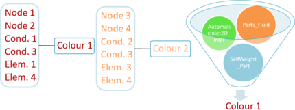
In our implementations we used a process to set the BC (both Neumann or Dirichlet). In order to preserve that information after remeshing we need to create an identification system, so we are able to create an unique ID that will allow us to reconstruct the submodelpart structure after remeshing, this methodologies are commonly called colour identification. Fig. 31 shows the concept of this idea.
|
| Figure 31: Concept of colours |
This work has been supported by the Spanish Government program FPU: FPU16/02697. The authors gratefully acknowledge the received support.
9 Compliance with Ethical Standards
This study was funded by the Spanish Government program FPU: FPU16/02697. The authors declare that they have no conflict of interest.
BIBLIOGRAPHY
[1] Zienkiewicz, O. C. and Zhu, J.Z. and Taylor, Robert L. The Finite Element Method: its Basis and Fundamentals. ISBN 978-1-85617-633-0
[2] Zárate F. and Oñate E., A simple FEM-DEM technique for fracture prediction in materials and structures, Computational particle mechanics, 2, page 301-314 (2015)
[3] Zárate F., Cornejo A. and Oñate E., A three-dimensional FEM–DEM technique for predicting the evolution of fracture in geomaterials and concrete, Computational particle mechanics, 5, pages 411-420 (2018)
[4] M. S. Shephard, N. A. B. Yehia, G. S. Burd, and T. J. Weidner. Automatic crack propagation tracking. Computers and Structures, 20, pages 211–223 (1985)
[5] Wawrzynek P. A. and Ingraffea A. R., An interactive approach to local remeshing around a propagating crack. Finite Elements in Analysis and Design, 5, pages 87-96 (1989)
[6] Bittencourt T. N., Wawrzynek P. A., IngraffeaA. R. and J. L. Sousa, Quasi-automatic simulation of crack propagation for 2D lefm problems, Engineering Fracture Mechanics, 55, pages 321-334 (1996)
[7] Trädegård A., Nilsson F., and Östlund S., Fem-remeshing technique applied to crack growth problems, Computer Methods in Applied Mechanics and Engineering, 160, pages 115-131 (1998)
[8] Bouchard P.O., Bay F., Chastel Y. and Tovena I., Crack propagation modelling using an advanced remeshing technique, Computer methods in applied mechanics and engineering, 189, pages 723-742 (2000)
[9] Zienkiewicz OC., Zhu JZ., The superconvergent patch recovery (SPR) and adaptive finite element refinement, Comput Methods Appl Mech Eng, 101, pages 207-224 (1992)
[10] Zienkiewicz O.C. and Zhu J.Z., A simple error estimator and adaptive procedure for practical engineering analysis, Int. J. Numer. Methods Eng, 24, pages 337–357 (1987)
[11] Babuška I. and Rheinboldt C., A-posteriori error estimates for the finite element method, Int. J. Numer. Methods Eng, 12, pages 1597–1615 (1978)
[12] Cervera M., Chiumenti M., Agelet de Saracibar C., Shear band localization via local J2 continuum damage mechanics, Comput Methods Appl Mech Eng, 193, pages 849-880 (2004)
[13] Cervera M., Chiumenti M., Codina R., Mixed stabilized finite element methods in nonlinear solid mechanics part I: formulation, Comput Methods Appl Mech Eng, 199, pages 2559-2570 (2010)
[14] Cervera M., Chiumenti M., Codina R., Mixed stabilized finite element methods in nonlinear solid mechanics part II: strain localization, Comput Methods Appl Mech Eng, 199, pages 2571-2589 (2010)
[15] Clough R.W., The stress distribution of Norfork dam. Technical Report 19, Department of Civil Engineering, University of California, Berkley, California, USA (1962)
[16] D. Ngo and A. C. Scordelis, Finite element analysis of reinforced concrete beams, ACI Journal, 64, pages 152-163 (1967)
[17] A. H. Nilson, Nonlinear analysis of reinforced concrete by the finite element method, 65, pages 757-766 (1968)
[18] Cervera M., An orthotropic mesh corrected crack model, Computer Methods in Applied Mechanics and Engineering, 197, pages 1603-1619 (2008)
[19] Belytschko T. and Black T., Elastic crack growth in finite elements with minimal remeshing, International journal for numerical methods in engineering, 45, pages 601-620 (1999)
[20] Moës N., Dolbow J. and Belytschko T., A finite element method for crack growth without remeshing, International journal for numerical methods in engineering, 46, pages 131-150 (1999)
[21] N. Sukumar, Moës N., Moran B. and Belytschko T., Extended finite element method for three-dimensional crack modelling, International journal for numerical methods in engineering, 48, pages 1549–1570 (2000)
[22] Sukumar N., Chopp D. L., Moës N., and Belytschko T., Modeling holes and inclusions by level sets in the extended finite-element method, Computer methods in applied mechanics and engineering, 190, pages 813-833 (2001)
[23] Moës N. and Belytschko T., Extended finite element method for cohesive crack growth, Engineering fracture mechanics, 69, pages 813-833 (2002)
[24] Melenk J.M. and Babuška I., The partition of unity finite element method: basic theory and applications, Computer methods in applied mechanics and engineering, 139, pages 289-314 (1996)
[25] Griebel M. and Schweitzer M.A., A particle-partition of unity method for the solution of elliptic, parabolic, and hyperbolic pdes, SIAM Journal on Scientific Computing, 22, pages 289-314 (2000)
[26] Gasser T. C. and Holzapfel G. A., 3D crack propagation in unreinforced concrete.: A two-step algorithm for tracking 3d crack paths, Computer Methods in Applied Mechanics and Engineering, 195, pages 5198-5219 (2006)
[27] Rashid Y.R., Ultimate strength analysis of prestressed concrete pressure vessels, Nuclear Engineering and Design, 7, pages 334-344 (1968)
[28] Pietruszczak S.T. and Mroz Z., Finite element analysis of deformation of strain-softening materials, International Journal for Numerical Methods in Engineering, 17, pages 327-334 (1981)
[29] Bažant Z.P. and Oh B.H., Crack band theory for fracture of concrete, Matériaux et construction, 16, pages 155-177 (1983)
[30] Ladyzhenskaya O.A., Solution “in the large” to the boundary value problem for the Navier-Stokes equations in two space variables, In Sovjet Physics Dokl, 123, pages 1128-1131 (1958)
[31] Babuška I., The finite element method with lagrangian multipliers, Numerische Mathematik, 20, pages 179-192 (1973)
[32] Silvester D.J., Optimal low order finite element methods for incompressible flow, Computer methods in applied mechanics and engineering, 111, pages 357-368 (1994)
[33] Mijuca D., On hexahedral finite element hc8/27 in elasticity, Computational mechanics, 33, pages 466-480 (2004)
[34] Martinez X., Oller S. and Barbero E., Caracterización de la delaminación en materiales compuestos mediante la teoría de mezclas serie/paralelo, Revista Internacional de Métodos Numéricos para Cálculo y Diseño en Ingeniería, 27, pages 189-199 (2011)
[35] Lee Y., Park K.C., Numerically generated tangent stiffness matrices for nonlinear structural analysis, Computer methods in applied mechanics engineering, 191, pages 5833-5846 (2002)
[36] Cundall PA. Strack ODL., A discrete numerical model for granular assemblies, Geotechnique, 29, pages 47-65 (1979)
[37] Labra C. and Oñate E., High-density sphere packing for discrete element method simulations, Commun Numer Meth Eng, 25, pages 837-849 (2009)
[38] Oñate E. and Zárate F. and Miquel J. and Santasusana M. and Celigueta MA. and Arrufat F. and Gandijota R. and Valiullin K. and Ring L., A local constitutive model for the discrete element method. Application to geomaterials and concrete, Comput Part Mech, 2, pages 139-160 (2015)
[39] Williams J. and O’Connor R., Discrete element simulation and contact problem, Arch Comput Methods Eng, 6, pages 279-304 (1999)
[40] Celigueta MA., Latorre S., Arrufat F. and Oñate E., Accurate modelling of the elastic behavior of a continuum with the Discrete Element Method, Computational Mechanics, 60, pages 997-1010 (2017)
[41] Oller S., Un modelo de daño continuo para materiales friccionales, Barcelona (1988)
[42] Lubliner J., Oliver J., Oller S., Oñate E., A plastic-damage model for concrete, International Journal of Solids and Structures, 25, pages 299-326 (1989)
[43] Oller S., Oñate E., Oliver J., Lubliner J., Finite element nonlinear analysis of concrete structures using a “plastic-damage model”, Engineering Fracture Mechanics, 35, pages 219-231 (1990)
[44] Casas G. and Mukherjee D. and Celigueta MA. and Zohdi TI. and Oñate E., A modular partitioned discrete element framework for industrial grain distribution systems with rotating machinery, Computational Particle Mechanics, 4, pages 181-198 (2017)
[45] Thornton C. and Cummins SJ. and Cleary PW.,An investigation of the comparative behaviour of alternative contact force models during inelastic collisions, Powder Technology, 233, pages 30-46 (2013)
[46] Cervera M., Chiumenti M. and Codina R., Mesh objective modelling of cracks using continuous linear strain and displacements interpolations, Int J Numer Methods Eng, 87, pages 962-987 (2011)
[47] Cervera M., Barbat G. and Chiumenti M., Finite element modeling of quasi-brittle cracks in 2D and 3D with enhanced strain accuracy, Computational Mechanics, 60 , pages 767–796 (2017)
[48] P. Dadvand, R. Rossi, E. Oñate, An Object-oriented Environment for Developing Finite Element Codes for Multi-disciplinary Applications. Computational Methods in Engineering (2010)
[49] Thompson J.F., Warsi Z.U.A, Boundary-fitted coordinate systems for numerical solution of partial differential equations, J. Comput. Phys., 47, pages 1–108 (1982)
[50] Bowyer A., Computing Dirichlet tessellations, Comput. J., 24(2) pages 162–166 (1981)
[51] Lo S.H., A new mesh generation scheme for arbitrary planar domains, Int. J. Numer. Methods Eng., 21 pages 1403–1426 (1985)
[52] M.A. Yerry, M.S. Shephard, Automatic three-dimensional mesh generation by the modified octree technique, Int. J. Numer. Methods Eng. 20 (1984) 1965–1990.
[53] Babuška I., Rheinboldt C., A-posteriori error estimates for the finite element method, Int. J. Numer. Methods Eng., 12 pages 1597–1615 (1978)
[54] Babuška I. and Rheinboldt C., Adaptive approaches and reliability estimates in finite element analysis, Comput. Methods Appl. Mech. Eng., 17 (18), pages 519–540 (1979)
[55] Chiaruttini V., Geoffroy D., Riolo V. and BonnetM. , An adaptive algorithm for cohesive zone model and arbitrary crack propagation. Revue Européenne de Mécanique Numérique/European Journal of Computational Mechanics, 21, pages 208-218 (2012)
[56] Jirásek M., Chapter 8 Nonlocal Damage Models 8.1 Basic Types of Nonlocal Damage Formulations.
[57] Zienkiewicz O.C., Phillips D.V., An automatic mesh generation scheme for plane and curved surfaces by isoparametric coordinates, Int. J. Numer. Methods Eng., 3, pages 519–528 (1971)
[58] Alauzet F., Metric-Based Anisotropic Mesh Adaptation. Course material, CEA-EDF-INRIA Schools. Numerical Analysis Summer School (2007)
[59] Tremblay P., 2-D, 3-D and 4-D Anisotropic Mesh Adaptation for the Time-Continuous Space-Time Finite Element Method with Applications to the Incompressible Navier-Stokes Equations. PhD thesis Ottawa-Carleton Institute for Mechanical and Aerospace Engineering, Department of Mechanical Engineering, University of Ottawa. 2007
[60] Frey P.J. and Alauzet F., Anisotropic mesh adaptation for CFD computations. Comput. Methods Appl. Mech (2004)
[61] Frey P.J. and Alauzet F., Anisotropic mesh adaptation for transient flows simulations.
[62] Bellet M., Adaptive mesh technique for thermal–metallurgical numerical simulation of arc welding processes, International Journal for Numerical Methods in Engineering (2008)
[63] Dobrzynski C.. MMG3D: User Guide. [Technical Report] RT-0422, INRIA. 2012. hal-00681813
[64] Dapogny C., Dobrzynski C. and Frey P., Three-dimensional adaptive domain remeshing, implicit domain meshing, and applications to free and moving boundary problems, hal-00804636 (2013)
[65] Rockafellar, R. Tyrrell; Wets, Roger J-B . Variational Analysis. Springer-Verlag. p. 117. ISBN 3-540-62772-3 (2015)
[66] Wessner, Wilfried and Ceric, Hajdin and Heitzinger, Clemens and Hössinger, Andreas and Selberherr, Siegfried. Anisotropic mesh adaption Governed by a Hessian Matrix Metric
[67] Alauzet, Frédéric, Frey and Pascal, Estimateur d'erreur géométrique et métriques anisotropes pour l'adaptation de maillage. Partie I : aspects théoriques. INRIA RR-4759
[68] Buchholz F., Chergui A. and Richard., Analyses and experimental results of crack growth under general mixed mode loading conditions, Eng Fract Mech, 71, pages 455-468 (2004)
[69] Oliver J., Cervera M., Oller S. and Lubliner J., Isotropic damage models and smeared crack analysis of concrete, Second international conference on Computer Aided Analysis and Design of Concrete Structures, (1990)
Document information
Published on 05/06/20
DOI: 10.1007/s40571-019-00306-4
Licence: CC BY-NC-SA license
Share this document
Keywords
claim authorship
Are you one of the authors of this document?