| Line 694: | Line 694: | ||
[8] Veletsos A., Yang J. Earthquake response of liquid storage tanks. Proceedings 2nd Engineering Mechanics Specialty Conference, ASCE. Raleigh, (NC), 1977. | [8] Veletsos A., Yang J. Earthquake response of liquid storage tanks. Proceedings 2nd Engineering Mechanics Specialty Conference, ASCE. Raleigh, (NC), 1977. | ||
| − | [9] Malhotra | + | [9] Malhotra P.K., Wenk T., Wieland M. Simple procedure for seismic analysis of liquid-storage tanks. Struct. Eng. Int., 10(3):197-201, 2000. |
[10] European Committee for Standarization (CEN). Eurocode 8. Design of Structures for Earthquake Resistance. Part 4: Silos, tanks and pipelines. CEN: Brussels, 2006. | [10] European Committee for Standarization (CEN). Eurocode 8. Design of Structures for Earthquake Resistance. Part 4: Silos, tanks and pipelines. CEN: Brussels, 2006. | ||
| − | [11] Epstein | + | [11] Epstein H. Seismic design of liquid-storage tanks. J. Struct. Div., 102:1659-1673, 1976. |
| − | [12] Graham | + | [12] Graham E., Rodriguez A. The characteristics of fuel motion which affect airplane dynamics. Report SM 14212, Douglas Aircraft Company, Santa Monica (CA), 1951. |
| − | [13] Ibrahim | + | [13] Ibrahim R. Liquid sloshing dynamics: Theory and applications. New York (NY): Cambridge University Press, 2005. |
| − | [14] Langhaar | + | [14] Langhaar H. Energy methods in applied mechanics. Krieger: Malabar (FL), 1962. |
| − | [15] Minowa | + | [15] Minowa C. Dynamic analysis for rectangular water tanks. Recent Adv. Lifeline Earthquake Engineering, Japan, 1980. |
| − | [16] Zhu | + | [16] Zhu F. Rayleigh-Ritz method in coupled fluid-structure interacting systems and its applications. J. Sound Vib., 186:543-550, 1995. |
| − | [17] Moradi | + | [17] Moradi R., Behnamfar F., Hashem S. Mechanical model for cylindrical flexible concrete tanks undergoing lateral excitation. Soil Dyn. Earthq. Eng., 106:148–162, 2018. |
| − | [18] Kim | + | [18] Kim J.K., Koh H.M., Kwahk I.J. Dynamic response of rectangular flexible fluid containers. J. Eng. Mech., 122(9):807-817, 1996. |
| − | [19] Rashed | + | [19] Rashed A.A., Iwan W.D. Dynamic analysis of short-length gravity dams. J. Eng. Mech., 111(8):1067-1083, 1985. |
| − | [20] Zhao | + | [20] Zhao D., Hu Z., Chen G., Lim S., Wang S. Nonlinear sloshing in rectangular tanks under forced excitation. In.t J. Nav Arch. Ocean Eng., 10:545-565, 2018. |
| − | [21] Ning | + | [21] Ning D.Z., Song W.H., Liu Y., Teng B. A boundary element investigation of liquid sloshing in coupled horizontal and vertical excitation. J. Appl. Math., 2012:1-20, 2012. [https://www.hindawi.com/journals/jam/2012/340640/ DOI: 10.1155/2012/340640] |
| − | [22] Hu | + | [22] Hu Z., Zhang X., Li X., Li Y. On natural frequencies of liquid sloshing in 2-D tanks using boundary element method. Ocean. Eng., 153:88–103, 2018. [https://doi.org/10.1016/j.oceaneng.2018.01.062 https://doi.org/10.1016/j.oceaneng.2018.01.062]. |
| − | [23] Hwang | + | [23] Hwang I.T., Ting K. Boundary element method for fluid-structure interaction problems in liquid storage tanks. J. Press. Vessel. Technol., 111(4):435-440, 1989. [https://doi.org/10.1115/1.3265701 https://doi.org/10.1115/1.3265701]. |
| − | [24] Taylor | + | [24] Taylor R.E., Wu G.X., Bai W., Hu Z.Z. Numerical wave tanks based on finite element and boundary element modeling. J. Offshore Mech. Arctic Eng., 130(3):031001, 2008. |
| − | [25] Wu | + | [25] Wu G.X., Ma Q.W., Taylor R.E. Numerical simulation of sloshing waves in a 3D tank based on a finite element method. Appl. Ocean Res., 20:337–355, 1998. |
| − | [26] Aslam | + | [26] Aslam M. Finite element analysis of earthquake-induced sloshing in axisymmetric tanks. Int. J. Numer. Methods Eng., 17:159-170, 1981. |
| − | [27] Babu | + | [27] Babu S.S., Bhattacharyya S. Finite element analysis of fluid-structure interaction effect on liquid retaining structures due to sloshing. Comput. Struc., 59(6):1165-1171, 1996. |
| − | [28] Arafa | + | [28] Arafa M. Finite element analysis of sloshing in rectangular liquid-filled tanks. J. Vib. Control, 13(7):883–903, 2007. [https://journals.sagepub.com/doi/10.1177/1077546307078833 DOI: 10.1177/1077546307078833]. |
| − | [29] Cho | + | [29] Cho J.R., Lee H.W. Non-linear finite element analysis of large amplitude sloshing flow in two-dimensional tank. Int. J. Numer. Methods Eng., 61(4):514–531, 2004. [https://onlinelibrary.wiley.com/doi/abs/10.1002/nme.1078 DOI: 10.1002/nme.1078]. |
| − | [30] Hernández | + | [30] Hernández H., Hernández A., Valdés G. Non-linear sloshing effect on storage tanks subjected to high earthquake ground motion. Rev. Int. Métodos Numer. Calc. Diseño Ing., 31(3):198–206, 2015. Spanish. [http://dx.doi.org/10.1016/j.rimni.2014.09.002 http://dx.doi.org/10.1016/j.rimni.2014.09.002]. |
| − | [31] Frandsen | + | [31] Frandsen J.B, Bortwick A.G. Simulation of sloshing motions in fixed and vertically excited containers using a 2-D inviscid σ-transformed finite difference solver. J. Fluids Struct., 18:197–214, 2003. |
| − | [32] Cook | + | [32] Cook R.D., Malkus D.S., Plesha M.E., Witt R.J. Concepts and applications of the finite element analysis. 4th ed. John Wiley and Sons: New York (NY), 2002. |
| − | [33] Housner | + | [33] Housner G.W. Limit design of structures to resist earthquakes. Proc First World Conference on Earthquake Engineering, Berkeley (CA), 1956. |
| − | [34] Uang | + | [34] Uang C.M., Bertero V.V. Evaluation of seismic energy in structures. Earthq. Eng. Struct. Dyn., 19(1):77-90, 1990. |
| − | [35] Koh | + | [35] Koh H.M., Kim J.K., Park J.H. Fluid—structure interaction analysis of 3-d rectangular tanks by a variationally coupled BEM-FEM and comparison with test results. Earthq. Eng. Struct. Dyn., 27(2):109-124, 1998. |
| − | [36] Dogangun | + | [36] Dogangun A., Livaoglu R. Hydrodynamic pressures acting on the walls of rectangular fluid containers. Struct. Eng. Mech., 17(2):203-214, 2004. |
| − | [37] Flores | + | [37] Flores C.B. Comportamiento mecánico de tanques atmosféricos de almacenamiento. Tesis de maestría. Escuela Superior de Ingeniería y Arquitectura (ESIA), Instituto Politécnico Nacional (IPN), Ciudad de México, 2009. |
Revision as of 14:30, 18 July 2022
Abstract
A proposal to estimate both the hydrodynamic pressures and the maximum wave height of liquids contained in rectangular tanks subjected to earthquake ground motions is presented. The computation procedure, based on the Rayleigh-Ritz method, assumes the fluid as a continuum and it does not use concentrated masses or springs. The solution is achieved by equating the seismic input energy of the system with the total kinetic energy of the fluid assuming liquid velocity fields. The resulting design formulas are simple and they are intended to simplify the seismic design of tanks. Numerical results lead to both the liquid maximum sloshing height and hydrodynamic pressure distributions that are similar to those obtained with other simplified methods and those estimated with the finite element method. Preliminary estimations of shear forces and bending moments for a numerical example resulted 13% and 6% larger (respectively) than the corresponding values obtained with the finite element method.
Keywords: Liquid-containing tanks, sloshing, hydrodynamic pressures, seismic design, Rayleigh-Ritz
1. Introduction
The seismic design of ground-supported tanks containing liquids requires the estimation of both the hydrodynamic pressures and the maximum sloshing height of the liquid, as indicated in typical design documents [1,2]. Currently, these documents include recommendations to compute the maximum sloshing height. The ASCE Standard relies on the document ACI 350.3 [3] for the computation of the hydrodynamic pressures.
In general, the formulas recommended by these documents to estimate the hydrodynamic pressures are based on the solutions presented by Housner [4,5]. On the other hand, the formula given by the ASCE Standard [1] to estimate the maximum height of the sloshing liquid is based on the classical solution of the Laplace differential equation given by Chen et al. [6] assuming no damping and the first vibration mode of the liquid. Other similar design recommendations for the seismic design of tanks (e.g., [7]) are also based on the Housner solutions to estimate hydrodynamic pressures and the sloshing height. A similar approach to that proposed by Housner, based on the works by Veletsos and Yang [8] as well as those of Malhorta [9], were incorporated in the Eurocode [10]. Epstein [11], based on the same works by Housner, presented updated formulas for the seismic design of cylindrical and rectangular tanks. Formulas obtained from solving the differential equations to estimate frequencies, pressures and sloshing heights were presented by Graham and Rodriguez [12,13]. These formulas, however, are not simple to use in design codes.
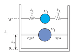
The equations derived by Housner have been widely used and they provide results with a precision that is good enough for engineering purposes. Housner obtained the design formulas assuming the tank as rigid and incorporating some simplifications of the liquid behavior during the tank vibration. The main simplification assumes that, during vibration, the liquid is divided in two parts: 1) a lower liquid mass that moves as a rigid body along with the tank, and 2) an upper liquid mass that moves relatively to the tank. The lower mass is identified as an impulsive mass and it causes pressures that are directly proportional to both the magnitude of this mass and the acceleration of the (rigid) tank. The upper mass is identified as a convective mass and it causes pressures that are due to the sloshing of the liquid. In the associated Housner’s analytical model (Figure 1), the continuum (liquid) consists of two concentrated masses: one rigidly attached to the lower part of the tank and the other that is connected with a spring to the upper part of the tank. Housner provided formulas to estimate: 1) the magnitudes of both masses, 2) the heights of each one and 3) the stiffness of the spring that connects the upper mass to the tank. Since each mass vibrates with a different frequency, the seismic response of each mass, as well as the forces on the tank walls, can be estimated with a seismic spectral analysis and a modal combination rule.
|
| Figure 1. Housner’s model with two concentrated masses to study the liquid movement |
The Rayleigh-Ritz method (RRM) [14] has been used to study vibrations of tanks. For instance, Minowa [15] studied the dynamic characteristics of elevated rectangular water tanks supported on frames and including water sloshing. Zhu [16] used the Rayleigh-Ritz method to estimate the natural frequencies of tanks considering fluid-structure interaction. In the study, full or partially filled tanks with inviscid, irrotational and compressible or incompressible fluids were considered. Zhu reported equations to compute the eigenvalues and eigenvectors of fluid-tank systems. Moradi et al. [17] proposed a mechanical model consisting of three concentrated masses to evaluate the seismic response of flexible cylindrical tanks. In their study, the Rayleigh-Ritz method was used for the analysis of liquid-shell systems. For design purposes, they present charts to estimate the dynamic parameters of the model.
Kim et al. [18] also studied the dynamic response of rectangular flexible tanks using the RRM. Rashed and Iwan [19] used the Rayleigh-Ritz method to express the tank wall displacements as a linear combination of admissible functions, while the liquid pressure equations were obtained with analytical solutions based on the method of separation of variables. In all these studies the RRM was applied to approximate the displacement field of the tank plates (walls or slab) while the liquid equation of motion was obtained with analytical methods, applying in many cases the method of separation of variables.
The seismic response of liquid-containing tanks has been also studied with numerical procedures. The main numerical methods include finite elements, boundary elements or finite differences. For example, Zhao et al. [20] used the boundary-element method (BEM) to study the nonlinear sloshing in rectangular tanks under base excitations. In their study, the hydrodynamic pressures were validated with experimental tests. Ning et al. [21] also used the BEM to study sloshing of liquids in tanks subjected to both horizontal and vertical excitations. Hu et al. [22] studied the natural frequencies of 2D tanks using the BEM.
The finite-element method (FEM) has also been used to study tanks subjected to ground motions. For instance, Hwang and Ting [23] combined the BEM and the FEM to study the dynamic response of liquid storage tanks subjected to earthquake ground motions. Taylor et al. [24] also combined both finite and boundary elements to model the interaction of nonlinear waves in tanks. Wu et al. [25] analyzed the sloshing waves in 3D tank using the FEM. Aslam [26] also studied sloshing in cylindrical tanks induced by ground motions. Babu and Bhattacharyya [27] studied the fluid-structure interaction effect on liquid-retaining structures due to sloshing using finite element analysis. Other studies using the FEM include Arafa [28] and Cho and Lee [29].
The finite-difference method (FDM) has been used, for instance, by Chen et al. [6], by Hernandez et al. [30] and by Frandsen and Bortwick [31] to study the nonlinear sloshing of a liquid contained in cylindrical and rectangular tanks subjected to ground motions.
The studies referred in the previous paragraphs either used the Rayleigh-Ritz method or numerical procedures to estimate dynamic characteristics of tanks containing fluids. Such works are not directly applicable for design because the associated procedures or formulas are elaborate.
The aim of the present work is to present simple design equations to estimate both the distribution of tank wall hydrodynamic pressures and the liquid maximum sloshing height. The proposed formulas are obtained with a model that does not use concentrated masses or springs. It assumes the liquid as a continuum. The solution is obtained by establishing an equilibrium between the system seismic input energy and the maximum fluid kinetic energy. The solution follows the Rayleigh-Ritz method [14] in the sense that the infinite number of degrees of freedom (d.o.f.) of the liquid is reduced to a small number of d.o.f. by assuming an approximating field [32]. In this work, the approximating fields are both the lateral and the vertical displacements/velocities of the fluid.
2. A method to estimate pressures
2.1 Tank geometry and liquid velocity fields
In this section, the Rayleigh-Ritz method is used to obtain expressions to estimate the liquid-sloshing height and the wall pressures in a liquid-storage rectangular tank subjected to an earthquake ground motion. The tank is assumed as rigid and trial functions are proposed for both the vertical () and the horizontal () fluid velocities. The basic assumption used to obtain the main design parameters is to equate the seismic input energy of the liquid with its maximum kinetic energy. In the solution, a velocity potential is not required.
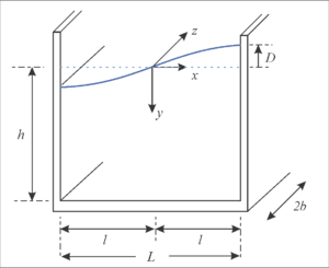
An open rectangular tank is shown in Figure 2, wherein the system of reference is located at the center of the initial liquid surface. In this figure, a surface of the liquid during sloshing is also illustrated. It is assumed that the fluid moves according to its first sloshing mode in a steady-state motion with constant peak wave . The variable represents the maximum sloshing liquid height at . In this work, this sloshing height is assumed as the main variable to be determined and it is taken as a generalized coordinate [30] within the Rayleigh-Ritz method. The initial height of the water is and the tank width is equal to . The total tank length is assumed equal to , although the analysis can be completed for a length equal to 1.0, when the ground motion direction is along the direction.
|
| Figure 2. Geometry of a rigid rectangular tank |
For the first sloshing mode, the shape of the water surface can be approximated with the following admissible fields for horizontal and vertical displacements, respectively
|
|
(1) |
|
|
(2) |
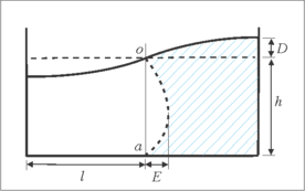
where is the liquid circular frequency and is the time. These fields lead to maximum fluid horizontal displacement at the bottom for and maximum vertical displacement of the liquid of the surface at . They also lead to , at the tank bottom (). The horizontal and vertical velocity fields result. The liquid movement resulting of these displacement fields is illustrated in Figure 3. In these equations is the time.
|
| Figure 3. Fluid displacement |
In these fields, the variable is the maximum horizontal displacement of the fluid (Figure 3). The liquid volume reduction that occurs at one side of the tank when the surface lowers should be equal to the volume increment at the other side of the tank (Figure 3). Therefore the maximum horizontal displacement () can be expressed in terms of the maximum vertical displacement ():
|
|
(3) |
The velocity fields resulting of these displacement fields are given by the following equations after taking derivatives with respect to the time :
|
|
(4) |
|
|
(5) |
Using Eq. (3) in (4), the field of the horizontal velocities results as follows
|
|
(6) |
2.2 Energy balance and liquid maximum sloshing height
The total kinetic energy of the fluid can be estimated by integrating the amount 0.5(), that corresponds to the kinetic energy of each mass differential , over the liquid volume:
|
|
(7) |
In these expressions, is the velocity of each particle and
|
|
(8) |
Assuming that the liquid is homogeneous with density equal to , the total maximum kinetic energy of the fluid due to the horizontal velocity is
|
|
(9) |
Similarly, the maximum kinetic energy due to the vertical velocity is
|
|
(10) |
The total kinetic energy of the fluid, assuming that both and occur at the same time, results
|
|
(11) |
The (input) energy that an earthquake introduces to the liquid can be estimated with the following expression [33-34], where is the liquid effective mass and is the spectral velocity for the liquid period . Notice that system does not include the mass of the tank.
|
|
(12) |
To obtain the spectral velocity, an estimate of the fundamental vibration frequency is required. Graham and Rodríguez [12-13], as well as Chen et al. [6], give the following formula for the modal frequency ():
|
|
(13) |
where for asymmetric modes, and for symmetric modes. The estimation of the fundamental vibration frequency in the Housner’s model is based on the values of and (Figure 1).
The effective mass can be estimated using a weight function similar to the function used for the horizontal velocity field
|
|
(14) |
Computing the definite integrals and simplifying
|
|
(15) |
If the total maximum kinetic energy (Eq. (11)) is set equal to the liquid input energy (Eq. (12)), an expression for can be obtained. This assumes that when the maximum kinetic energy occurs, the potential energy is equal to zero. Thus, the expression to estimate the maximum liquid sloshing height is
|
|
(16) |
This value can be used to completely define both the displacement and the velocity fields.
2.3 Lateral hydrodynamic pressures
The lateral pressure on the wall tank can be obtained with the Bernoulli equation which, including the lateral ground acceleration and the hydrostatic pressure , results:
|
|
(17) |
where is the velocity potential function, is the ground motion peak acceleration and is the gravity acceleration. This equation applies for inviscid, incompressible and irrotational fluids.
The pressure term can be obtained as follows. Taking the partial derivative of this term with respect to
Thus, the pressure associated to the velocity results:
The maximum vertical acceleration at the wall results (after Eq. (5)):
|
|
(18) |
Since the lateral (relative) acceleration is equal to zero at the wall, the maximum amplitude of the wall pressure results (to evaluate the constant notice that at ):
|
|
(19) |
As for the pressure term :
|
|
(20) |
At the wall, the amplitude of this pressure second term is:
|
|
(21) |
These two pressures ( and ) can be assumed as the “convective” pressure because both vary according to the liquid sloshing frequency. The pressure can be neglected [6] because its value is small, compared with the other terms.
The third pressure term (Eq. (17)) is related directly to the acceleration of the wall and it is identified as the impulsive pressure. Usually, this pressure has a larger magnitude than because in most cases its acceleration spectral ordinate is larger than the corresponding ordinate for the sloshing frequency. Since the tank wall is assumed rigid, the pressure computation with Eq. (17) would lead to a magnitude equal to (). In theory, the pressure would vary according to the ground shaking.
To be consistent with the estimation of pressures and , wherein an effective mass was considered, the same shape function used to compute is used here (Eq. (13)) to estimate . Thus, for , the shape function leads to the following pressure distribution (with a value of at the tank base and zero at the liquid free surface):
|
|
(22) |
Finally, an estimation of the total hydrodynamic pressure on the wall (no including the hydrostatic one) can be obtained, by combining the pressures having different frequencies, using the square root of the sum of the squares (SRSS) rule. Thus:
|
|
(23) |
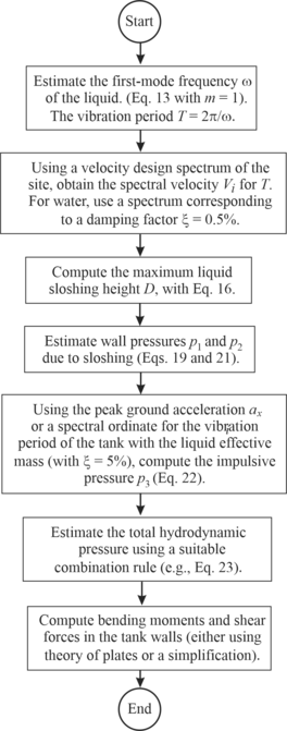
As a summary of the proposed method, Figure 4 shows a diagram with the steps involved in the computation of both the liquid sloshing height and the total hydrodynamic pressures.
|
| Figure 4. Steps to compute both the liquid sloshing height and the hydrodynamic pressures according to the proposed method |
3. Numerical example
A numerical example is presented in this section to compare the solutions obtained with the following methodologies: a) ASCE Standard [1,3], b) Housner [4,5], and c) the method presented in this work. A computation using the CFE Code [2,37] is also included, although its formulas are similar to those obtained by Housner. These computations are compared with the FEM results published by Koh et al. [35,36].
The geometry of the tank containing water is defined with the following values: m ( m) and m. The system is excited with the NS component of the 1949 El Centro (Imperial Valley) earthquake ground motion (the perpendicular component is neglected). For comparison purposes, no load and resistance factors are included in the computations. No overstrength factors are used either. In all cases, wall pressures are computed for a unit width .
3.1 ASCE standard
Section 15.7 of the Standard (Tanks and Vessels) contains design recommendations for tanks supported at the base. According to this Standard [1], damping for sloshing (convective) effects shall be taken as 0.5% in the case of water. Since the impulsive effects are related to the mass rigidly attached to the tank, in this section the impulsive term is associated to the pressure in Eq. (17). Similarly, the convective effects are associated to the terms and of the same equation. No vertical forces associated to vertical ground accelerations are considered here.
According to the Standard, the natural period of the first (convective) mode of sloshing is (using as the diameter ' of the equation given by the Standard)
|
|
(24) |
This formula uses English units, so , and : s.
The ACI 350.3 [3], which is also referred by the Standard, leads to the value of s, which is almost equal to the one obtained after using Eq. (13) [12,16].
As for the water sloshing maximum height, the Standard gives the following formula:
|
|
(25) |
where is the Importance Factor and is the spectral acceleration of the sloshing liquid based on its vibration period and a damping factor . Considering = 5 s, the spectral ordinate is . Moreover, using , the sloshing height results equal to m. Equation (25) is practically the same as the one given by Chen et al. [6] for zero damping. Notice that the ACI-350.3 gives the following formula to estimate the maximum sloshing height
|
|
(26) |
where the product between parenthesis can be seen as the spectral acceleration since is the zone peak ground acceleration and is the coefficient of spectral acceleration, which is dependent of the vibration period. The factor is the soil coefficient and is the importance factor taken equal to Thus, with = 0.075, the sloshing height results m.
For the computation of pressures and their resultants, the Standard recommends the use of the method given by the ACI 350.3 [3]. First, the lateral forces are computed. The impulsive force is simply evaluated as the product of the effective impulsive weight and the spectral acceleration (normalized with respect to ); i.e.,
|
|
(27) |
The impulsive force is computed with . According to the ACI 350.3 the impulsive weight is , where is the total liquid weight, which for results kN = 180,000 kgf. Notice that the weight obtained with the effective mass given by Eq. (15) for the proposed method ( kN = 145,890 kgf) is about 80% of .
Therefore kN = 89,640 kgf and kN = 31,195 kgf.
Similarly, the convective force is given by (with kN = 93,976 kgf):
|
|
(28) |
Considering = , (921.6 kN) = 69.1 kN = 7,048 kgf. According to the ACI 350.3, the pressures are obtained by applying the forces on each perpendicular wall with linear distributions (here is measured from the bottom up, m and m):
|
|
3.2 Housner
In this subsection, the wall pressures are computed taking into account Housner [4,5]. The impulsive pressure is computed with the following formula, where is measured from the liquid surface down (with and ):
|
|
(29) |
The convective pressure is:
|
|
(30) |
where and is an estimation of the maximum rotation of the liquid surface. To compute this value, an estimation of the sloshing height is required. Housner [5] gives the following equation to estimate it ( is the spectral displacement):
|
|
(31) |
Thus, the value of can be computed as follows:
|
|
(32) |
3.3 Method presented here
First, the maximum sloshing height is computed with Eq. (16). Using the spectral velocity m/s and with rad/s, the sloshing height results m. Then the pressures can be computed with Eqs. (19), (21) and (22). These pressures are combined with Eq. (23). The procedure follows the steps indicated in Figure 4.
3.4 CFE
The dynamic model as well as the formulas to estimate the sloshing height and the wall pressures are based on the Housner model. Therefore the estimation of is computed with Eq. (31), with . The formulas used to compute the pressures are (after some simplifications and with ):
|
|
(33) |
and
|
|
(34) |
where the coefficients and are the spectral accelerations computed for the vibrations periods of the impulsive and convective movements, respectively. The coefficients and are dimensionless values that describe the pressure variations in terms of the normalized height (). These graphs are similar to those included in Ref [36]. The CFE also recommends that the total pressure should be computed with the SRSS rule.
3.5 Comparisons
3.5.1 Sloshing heights
The liquid sloshing heights computed with each method are listed in Table 1. They vary between 51 and 75 cm. It can be observed that the smaller sloshing height is the one estimated with the finite element method [35] considering the wall thickness = 1.0 m (or rigid). Among the methods that assume the walls as rigid, the proposed method gives the nearest estimation to that computed with the FEM [35].
| Method | D [m] |
|---|---|
| Housner | 0.71 |
| Standard ASCE 7-16 | 0.63 |
| ACI-350.3 | 0.75 |
| Method presented here | 0.51 |
| CFE-2015 | 0.71 |
| Ko, Kim and Park ( m)* | 0.70 |
| Ko, Kim and Park ( m and rigid)* | 0.30 |
3.5.2 Convective pressures
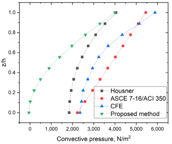
To show a complete perspective of the computed pressures, the convective pressures are computed separately for those methods were these pressures are available. Figure 5 shows the convective pressures computed for some methods. The smaller convective pressures are estimated by the proposed method; however, this is not relevant because the design of tanks is carried out with the total pressures. The separation of convective and impulsive pressures is just a computational device.
|
| Figure 5. Wall convective pressures computed with several methods |
3.5.3 Impulsive pressures
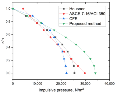
Figure 6 shows the impulsive pressures computed for some methods. Contrary to the convective pressures, the larger convective pressures at the tank base are estimated by the proposed method.
|
| Figure 6. Wall impulsive pressures computed with several methods |
3.5.4 Total hydrodynamic pressures
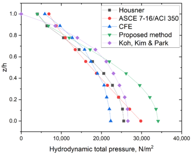
As for the total pressures, the total wall pressures are shown in Figure 7. The pressures computed in Cho and Lee [29] are also included in the figure. These values were computed with the finite element method (FEM) and are assumed here as the “exact” pressures.
|
| Figure 7. Total wall pressures computed with several methods |
3.5.5 Sher forces and bending moments at the tank walls
For the wall design, an estimation of both the shear forces () and the bending moments () is required. An analysis of the walls can be carried out taking into account a theory of plates (either thin plate theory or thick plate theory). In the estimation of these forces () and the bending moments () a finite element analysis of the complete tank can also be considered, however given the accuracy involved in the estimations of pressures, this refinement is in many cases not justified. An isolated plate with adequate boundary conditions seems to be enough for the computation of forces. Since the length/height ratio of the tank of this example is larger than 2.0, a vertical strip of wall can be idealized as a contilever beam supported at the base with a width equal to 1.0 m. This simplification is used here as a simple way to compare these moments among the methods. In the case of reinforced-concrete tanks the bending moment referred here can be used to obtain the wall vertical reinforcement.
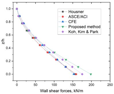
The distributions of shear forces per unit width are shown in Figure 8. It is clear that the distributions of these shear forces are similar among the methods. The shear forces computed with the proposed method resulted slightly larger than the finite element method (FEM) forces, given by Koh et al. [35]. The shear force at the wall base predicted by the proposed method resulted 13% larger than the value given by the FEM solution.
|
| Figure 8. Shear forces per unit width of wall computed with several methods |
The distributions of bending moments per unit width are shown in Figure 9. All distributions are similar among the methods. Again, the closer approximation to the finite element method (FEM) results [35], is the one obtained with the proposed method. The bending moment at the wall base predicted by the proposed method resulted only 6% larger than the value given by the FEM solution.
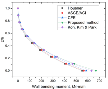
|
| Figure 9. Bending moments per unit width of wall computed with several methods |
4. Conclusions
A simple method to estimate both the liquid sloshing height and the wall pressures in tanks containing liquids is presented. The method is based on the Rayleigh-Ritz method applied to the liquid. To obtain these design parameters the total seismic input energy is made equal to the maximum total kinetic energy of the liquid for assumed liquid velocity fields. In the proposed method the tank is assumed rigid. Results indicate that the proposed method gives estimations of both the liquid sloshing height and the total hydrodynamic pressures similar to those obtained with both other simplified methodologies and using the finite element method.
The shear force and the bending moments computed with the proposed method resulted larger than the values computed with the solution obtained with the finite element method. For the example, the shear force at the wall base predicted by the proposed method resulted 13% larger than the value given by the FEM solution. As for the bending moment, the value at the wall base predicted by the proposed method resulted only 6% larger than the value given by the FEM solution. The proposed method seems to be simple enough that it can be used for design of rigid rectangular tanks. The methodology used for the proposed method can be extended to the study of cylindrical tanks. Moreover, the flexibility of the tank can be incorporated in the Rayleigh-Ritz solution proposing a displacement field for the walls and incorporating the corresponding strain energy. Additional examples with the proposed method are recommended before the method can be used extensively.
References
[1] American Society of Civil Engineers. ASCE/SEI 07-16. Minimum design loads and associated criteria for buildings and other structures. ASCE: Reston, Virginia, 2017.
[2] Comisión Federal de Electricidad. Manual de diseño de obras civiles – Diseño por sismo. CFE: Ciudad de Mexico, 2009. Spanish.
[3] American Concrete Institute. ACI 350.3-06: Seismic design of liquid-containing concrete structures and commentary ACI: Farmington Hills, 2006.
[4] Housner G.W. Dynamic pressures on accelerated fluid containers. Bull. Seismol. Soc. Am., 47:15-35, 1957.
[5] Housner G.W. The dynamic behavior of water tanks. Bull. Seismol. Soc. Am., 53:381-387, 1963.
[6] Chen W., Haroun M, Liu F. Large amplitude liquid sloshing in seismically excited tanks. Earthq. Eng. Struct. Dyn., 25:653-669, 1996.
[7] American Water Works Association. Welded carbon steel tanks for water storage. ANSI/AWWA D100-05 Standard. Denver, 2005.
[8] Veletsos A., Yang J. Earthquake response of liquid storage tanks. Proceedings 2nd Engineering Mechanics Specialty Conference, ASCE. Raleigh, (NC), 1977.
[9] Malhotra P.K., Wenk T., Wieland M. Simple procedure for seismic analysis of liquid-storage tanks. Struct. Eng. Int., 10(3):197-201, 2000.
[10] European Committee for Standarization (CEN). Eurocode 8. Design of Structures for Earthquake Resistance. Part 4: Silos, tanks and pipelines. CEN: Brussels, 2006.
[11] Epstein H. Seismic design of liquid-storage tanks. J. Struct. Div., 102:1659-1673, 1976.
[12] Graham E., Rodriguez A. The characteristics of fuel motion which affect airplane dynamics. Report SM 14212, Douglas Aircraft Company, Santa Monica (CA), 1951.
[13] Ibrahim R. Liquid sloshing dynamics: Theory and applications. New York (NY): Cambridge University Press, 2005.
[14] Langhaar H. Energy methods in applied mechanics. Krieger: Malabar (FL), 1962.
[15] Minowa C. Dynamic analysis for rectangular water tanks. Recent Adv. Lifeline Earthquake Engineering, Japan, 1980.
[16] Zhu F. Rayleigh-Ritz method in coupled fluid-structure interacting systems and its applications. J. Sound Vib., 186:543-550, 1995.
[17] Moradi R., Behnamfar F., Hashem S. Mechanical model for cylindrical flexible concrete tanks undergoing lateral excitation. Soil Dyn. Earthq. Eng., 106:148–162, 2018.
[18] Kim J.K., Koh H.M., Kwahk I.J. Dynamic response of rectangular flexible fluid containers. J. Eng. Mech., 122(9):807-817, 1996.
[19] Rashed A.A., Iwan W.D. Dynamic analysis of short-length gravity dams. J. Eng. Mech., 111(8):1067-1083, 1985.
[20] Zhao D., Hu Z., Chen G., Lim S., Wang S. Nonlinear sloshing in rectangular tanks under forced excitation. In.t J. Nav Arch. Ocean Eng., 10:545-565, 2018.
[21] Ning D.Z., Song W.H., Liu Y., Teng B. A boundary element investigation of liquid sloshing in coupled horizontal and vertical excitation. J. Appl. Math., 2012:1-20, 2012. DOI: 10.1155/2012/340640
[22] Hu Z., Zhang X., Li X., Li Y. On natural frequencies of liquid sloshing in 2-D tanks using boundary element method. Ocean. Eng., 153:88–103, 2018. https://doi.org/10.1016/j.oceaneng.2018.01.062.
[23] Hwang I.T., Ting K. Boundary element method for fluid-structure interaction problems in liquid storage tanks. J. Press. Vessel. Technol., 111(4):435-440, 1989. https://doi.org/10.1115/1.3265701.
[24] Taylor R.E., Wu G.X., Bai W., Hu Z.Z. Numerical wave tanks based on finite element and boundary element modeling. J. Offshore Mech. Arctic Eng., 130(3):031001, 2008.
[25] Wu G.X., Ma Q.W., Taylor R.E. Numerical simulation of sloshing waves in a 3D tank based on a finite element method. Appl. Ocean Res., 20:337–355, 1998.
[26] Aslam M. Finite element analysis of earthquake-induced sloshing in axisymmetric tanks. Int. J. Numer. Methods Eng., 17:159-170, 1981.
[27] Babu S.S., Bhattacharyya S. Finite element analysis of fluid-structure interaction effect on liquid retaining structures due to sloshing. Comput. Struc., 59(6):1165-1171, 1996.
[28] Arafa M. Finite element analysis of sloshing in rectangular liquid-filled tanks. J. Vib. Control, 13(7):883–903, 2007. DOI: 10.1177/1077546307078833.
[29] Cho J.R., Lee H.W. Non-linear finite element analysis of large amplitude sloshing flow in two-dimensional tank. Int. J. Numer. Methods Eng., 61(4):514–531, 2004. DOI: 10.1002/nme.1078.
[30] Hernández H., Hernández A., Valdés G. Non-linear sloshing effect on storage tanks subjected to high earthquake ground motion. Rev. Int. Métodos Numer. Calc. Diseño Ing., 31(3):198–206, 2015. Spanish. http://dx.doi.org/10.1016/j.rimni.2014.09.002.
[31] Frandsen J.B, Bortwick A.G. Simulation of sloshing motions in fixed and vertically excited containers using a 2-D inviscid σ-transformed finite difference solver. J. Fluids Struct., 18:197–214, 2003.
[32] Cook R.D., Malkus D.S., Plesha M.E., Witt R.J. Concepts and applications of the finite element analysis. 4th ed. John Wiley and Sons: New York (NY), 2002.
[33] Housner G.W. Limit design of structures to resist earthquakes. Proc First World Conference on Earthquake Engineering, Berkeley (CA), 1956.
[34] Uang C.M., Bertero V.V. Evaluation of seismic energy in structures. Earthq. Eng. Struct. Dyn., 19(1):77-90, 1990.
[35] Koh H.M., Kim J.K., Park J.H. Fluid—structure interaction analysis of 3-d rectangular tanks by a variationally coupled BEM-FEM and comparison with test results. Earthq. Eng. Struct. Dyn., 27(2):109-124, 1998.
[36] Dogangun A., Livaoglu R. Hydrodynamic pressures acting on the walls of rectangular fluid containers. Struct. Eng. Mech., 17(2):203-214, 2004.
[37] Flores C.B. Comportamiento mecánico de tanques atmosféricos de almacenamiento. Tesis de maestría. Escuela Superior de Ingeniería y Arquitectura (ESIA), Instituto Politécnico Nacional (IPN), Ciudad de México, 2009.Document information
Published on 20/07/22
Accepted on 07/07/22
Submitted on 06/03/22
Volume 38, Issue 3, 2022
DOI: 10.23967/j.rimni.2022.07.001
Licence: CC BY-NC-SA license
Share this document
Keywords
claim authorship
Are you one of the authors of this document?