LUZhongxiang (talk | contribs) |
LUZhongxiang (talk | contribs) |
||
| Line 73: | Line 73: | ||
{| style="text-align: center; margin:auto;" | {| style="text-align: center; margin:auto;" | ||
|- | |- | ||
| − | | <math display="inline">{S\left( x\right) ={S}_{max}exp(-\frac{{x}^{2}}{2{i}^{2}})</math> | + | | <math display="inline">{S\left( x\right) ={S}_{max}exp(-\frac{{x}^{2}}{2{i}^{2}})}</math> |
|} | |} | ||
| style="width: 5px;text-align: right;white-space: nowrap;" | (2-1) | | style="width: 5px;text-align: right;white-space: nowrap;" | (2-1) | ||
Revision as of 17:04, 8 September 2023
Abstract:This study utilizes ABAQUS finite element software to analyze embankment deformation during shield tunneling. Results reveal that shield tunneling effects are manageable.The left tunnel line successfully tunnels beneath the embankment, causing a maximum settlement of 8.7 mm, meeting regulations. The ground surface exhibits a "V"-shaped lateral settlement trough, approximately five times the tunnel centerline width. Conversely, the right tunnel line induces a more extensive impact, with a 12.2 mm maximum settlement.Different lateral settlement patterns emerge in soil at varying depths. The left tunnel creates a "V" shape, with slightly increasing settlement above the tunnel axis as depth increases, accompanied by narrower troughs. The right tunnel line results in a pronounced "W" shape, especially at the grouting layer depth.Horizontal displacement forms an "S" shape, with maximum displacement at positions ±i from the tunnel axis. The right tunnel line induces greater maximum horizontal displacement than the left.In summary, this numerical analysis provides insights into embankment deformation during shield tunneling, aiding in assessing the impact and guiding safe tunneling beneath embankments.
Keywords: shield tunnel finite element simulation Levee settlement data fitting
1. introduction
With the rapid development of urban transportation, the number and scale of urban cross-river tunnel constructions are also expanding. These tunnels, primarily built using large-diameter mud shield methods, have seen their outer diameters grow from approximately 11 meters [1] to about 15 meters [2]. Notably, these river-crossing tunnels must traverse through river embankments, inevitably causing soil disturbance, particularly during the construction of super-large diameter mud shield tunnels.Given the intricacy of embankment structures and the vital role that river embankments play in safeguarding the lives and property of communities on both sides of the river, it becomes crucial to adopt rational construction parameters and measures. This approach aims to minimize the impact of shield tunneling on embankment structures.
In recent years, the engineering field has accumulated some experience on the disturbance effect of shield tunneling through levees. Zhang Yazhou et al[3].used finite-difference software to establish a three-dimensional numerical model of Nanjing Weisan Road super-diameter shield tunnel crossing the Yangtze River embankment, and calculated the settlement law and overall stability of the embankment. With the Chengjiang West Road tunnel in Jiangyin as the background, Han Lei et al[4]. used the displacement control finite element method based on the formation loss rate to calculate the embankment settlement under different formation loss rates and put forward control suggestions. Based on monitoring data and Peck empirical formula, Li Zongliang et al. [5-6] analyzed the disturbance and settlement law of the Qiantang River levee during shield crossing construction of Qingchun Road Tunnel in Hangzhou City, and proposed settlement control measures when mud shield crossing the levee. Wu Weiyi et al[7]. applied FLAC3D finite difference program and combined with field measurement to calculate and analyze the deformation law of the levee caused by the mud-water balanced shield with a diameter of 11.68m penetrating the Qiantang River levee, and found that the transverse settling trough at the top of the levee was similar to that of the subway shield with a diameter of 6.34m, showing Gaussian normal distribution. Peck formula can still be used to estimate the settlement, but the variation of settlement amount and trough width with depth is not as obvious as that of 6.34m diameter subway shield. Huang Hai [8] studied the embankment surface settlement caused by the large-diameter shield tunneling under Qiantang River, and found that the transverse settlement trough of the levee basically accords with normal distribution, the settlement is the largest at the center of the tunnel axis, and the surface settlement away from the tunnel center gradually decreases, and the settlement is symmetrically distributed along the tunnel axis, which accords with the normal distribution curve proposed by Peck. Zhu Muyuan et al[9]., relying on the Jilou Road Tunnel project, analyzed the settlement rules and characteristics of the large embankment section during the process of shield tunnel through the levee through the field measured data, and adopted a fine dynamic simulation of the shield tunnel driving process, and found that the initial settlement rate of the large embankment section during the shield tail ejection stage was larger and more susceptible to disturbance than that of the ordinary flat section. And the top of the levee is more sensitive to the disturbance of deep soil. Xie Xiongyao et al[10]. used finite element software to establish a three-dimensional numerical model for the super-diameter shield tunneling levee across the Yangtze River, and carried out a fine simulation of the construction process on the basis of considering construction elements such as soil excavation, mud-water support, segment lining, grouting behind the wall and formation loss. This paper summarizes the technical measures of settlement control in slurry shield tunneling from 7 aspects, such as slurry pressure control and real-time measurement of synchronous grouting quantity. Lin, QB et al[11]. takes Liuyang River levee engineering section of Changsha Metro Line 6 as the engineering background, and studies the levee deformation under shield tunnel excavation condition. Wu Shiming et al[12].analyzed the risk sources of mud shield tunneling through levee engineering, discussed the causes, hazards and avoidance measures of the risks, and verified the rationality of the risk control measures by combining the engineering example of mud shield tunneling through levee in Qingchun Road Tunnel in Hangzhou. Most of the existing research results are the analysis of the settlement of levees, but there are few studies on the deep soil settlement and horizontal displacement characteristics of levees. Therefore, the analysis of three-dimensional deformation characteristics of levees after shield tunneling is helpful to understand the law and control the construction risk.
In this paper, the deformation (settlement and displacement) of the levee caused by the large diameter shield machine under the construction of the Jiangshan Road tunnel in Hangzhou is numerically calculated, and the three-dimensional deformation characteristics of the levee are studied.
2. Project overview and geological conditions
2.1 Project Overview
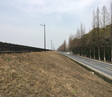
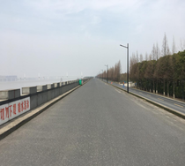
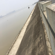
Genshandong Road Cross-River Tunnel is a significant infrastructure project located between Xiisha Bridge and Jiangdong Bridge, spanning a total length of 4462.26m. This tunnel plays a vital role in the region's transportation network, and its technical aspects are noteworthy for a comprehensive understanding.This shield tunnel features a single-layer lining with segment assembly. It boasts an impressive outer diameter of 14.5m, an inner diameter of 13.3m, a segment thickness of 0.6m, and a ring width of 2m. The tunnel comprises 10 "9+1" sections, and these sections are assembled with staggered joints, tightly secured by high-strength bolts. The construction of the shield tunnel begins at the eastern starting well of the Big River and proceeds westward. Upon crossing the mighty Qiantang River, it reaches its destination at the Xiasha receiving well. It's worth noting that when the shield tunneling machine pierces through the Qiantang River levee, it faces a significant challenge due to the levee's high deformation requirements caused by tidal influence. For a visual representation, please refer to Figure 1, which illustrates the current status of the levee.
|
|
|
2.2 Hydrogeological conditions and monitoring arrangement
The shield tunnel passes through various soil layers, including sandy silt, silt,silty clay, mucky clay,clay,Fully weathered rock and Moderately weathered rock. It's worth noting that the levee wasn't strengthened before shield construction. However, monitoring points were strategically placed on the levee to ensure safety. Let's delve into the specifics of the tunnel's soil layers and monitoring setup in Figure 2. Safety is a top priority in this project. Despite the absence of levee strengthening before shield construction, we've taken precautions by installing settlement monitoring points on the levee. These measures are crucial to ensure the stability and safety of the project.
3. Measured analysis of surface settlement of levees
3.1 Lateral surface settlement of levee top
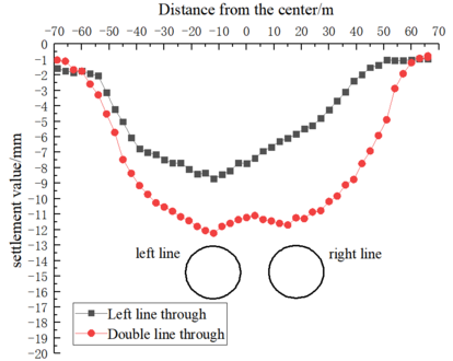
In Figure 3, we observe the settlement patterns above and around the tunnel axis. The most significant settlement occurs directly above the tunnel axis. For the left-line shield tunnel, the transverse surface settlement generally forms a 'V' shape distribution, with a maximum settlement of 8.7mm, directly above the left line. Conversely, after the right-line shield tunnel crosses the levee, the transverse surface settlement generally exhibits a 'W' shape distribution. Here, the maximum settlement reaches 12.2mm, which is still directly above the left line of the shield tunnel and greater than the surface settlement above the right line. Additionally, the surface settlement in the middle of the left and right lines is slightly less than the settlement value above the tunnel.
For the prediction of ground displacement caused by single-line tunnel excavation, the horizontal distribution estimation formula of ground settlement proposed by Peck is generally adopted in current engineering practice [13] :
|
|
(2-1) |
|
|
(2-2) |
S(x):Ground subsidence caused by ground loss;x:the distance from the tunnel center line;Smax:the maximum settlement caused by the formation loss at the center line of the tunnel;i:the width coefficient of surface settling trough;Vs:Stratum loss per unit length of tunnel;η:the formation loss rate, is the ratio of the surface subsidence trough area to the tunnel excavation area;R:the radius of tunnel excavation.
When the Peck formula is used to predict the transverse surface settlement, the most important thing is to determine the formation loss rate V1 and the width coefficient of sedimentation tank i. O'Reilly &New (1982) [14] proposed the following values in accordance with the experience of London:
|
|
(2-3) |
K:sedimentation tank width parameter;Z0:buried depth for the tunnel axis.
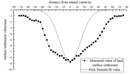
In the paper, Peck formula was used to fit the measured transverse surface settlement curve of the embankment top after the left line crossed the embankment, further compared the surface settlement of the embankment top, and evaluated the applicability of Peck formula in the project, as shown in Figure 4.
Upon analyzing Figure 4, we can observe that the variation in the surface settlement curve closely aligns with the Peck formula. However, it's noteworthy that the measured values in the field are slightly larger than those fitted by the Peck formula. This discrepancy may arise due to the greater structural weight of the levee compared to typical strata. Compared with shield tunneling in other general strata, the soil and water pressure, as well as settlement, beneath the levee excavation surface are greater at the same burial depth. This is influenced by the large diameter of the shield used. Given that the Peck formula remains applicable even in situations involving large-diameter shield tunnels, engineers can use it to quickly predict the distribution of transverse settling troughs at the top of the levee. This prediction considers the formation loss (Vs) caused by shield construction and the width coefficient of the settling trough (i). Such predictions are invaluable for assessing whether levee settlement values and uneven settlement slopes exceed deformation control thresholds, allowing timely adjustments to construction parameters.
3.2 Surface settlement of shield through various stages
The surface settlement caused by shield tunnel construction can be divided into five stages based on the relative position and formation mechanism of the shield tunnel and monitoring section. The following is a detailed description of each stage:
1) the shield approaches: the shield excavation face has not reached the monitoring section, and the distance is about 2 times the diameter of the shield.
2) the shield arrives: the excavation face of the shield has not reached the monitoring section, and the distance is 0~2 times the diameter of the shield.
3) the shield goes through: when the shield excavation face passes through the monitoring section, the distance is 1 times the diameter of the shield.
4) the shield leaves: when the shield excavation face leaves the monitoring section about 1 times the diameter of the shield.
5) Final stable times: about 10 times the diameter of the shield when the shield excavation face leaves the monitoring section.
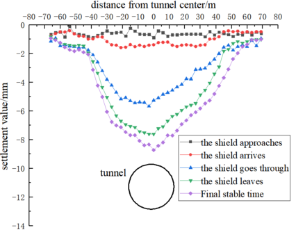
As shown in Figure 5, this is the lateral surface settlement curve of the levee at each stage of left-line shield construction. By comparing these curves, it can be observed that as the shield advances, surface settlement gradually increases. The width of the transverse settlement trough in the same section remains relatively constant, and the settlement curve becomes steeper. When the shield reaches the monitoring fault front (approximately 1D~2D away from the section,D: the tunnel diameter), a noticeable transverse settlement trough with a width of about 15~20 meters is generated. The maximum land settlement occurs at the center of the tunnel, with settlement decreasing as one moves farther away from the tunnel center.
Table 1 provides valuable insights into the percentage distribution of settlement in different stages of shield tunnel excavation. Understanding these percentages is crucial for assessing settlement patterns during the construction process. In the early settlement stage of the monitoring point, the settlement value accounts for 7% of the total settlement, which, while relatively small, should not be overlooked. Moving on to the arrival stage of the shield, we see that it contributes 14% of the total settlement. However, the phases of shield passage and post-shield passage are particularly critical, with these two stages contributing to a larger proportion of the total settlement, specifically 43% and 23%, respectively. In fact, settlements in these stages collectively account for approximately 66% of the total settlement value, making this phase the most concerning due to its rapid and substantial settlement changes. Finally, the late sedimentation stage produces around 13% of the total settlement value. To summarize, the percentage of settlement in various stages of shield tunnel excavation varies significantly. The early and late stages contribute relatively small percentages, while the arrival stage accounts for 14% of the total settlement. However, it's during the phases of shield passage and post-shield passage that settlement percentages are most substantial, combining to make up approximately 66% of the total settlement value. This phase is of particular concern due to its rapid and pronounced settlement changes.
Figure 5. Surface settlement curve of the left line shield crossing the levee at each stage
Table 1. Percentage of the total settlement at each stage of the monitoring point (%)
| Pre-arrival settlement of shield | Phase settlement of shield arrival | Phase settlement of the shield as it passes through | Phase settlement after shield passage | Long-term subsequent stage settlement |
| 7 | 14 | 43 | 23 | 13 |
4. Numerical analysis of levee deformation
To investigate the soil deformation characteristics of the levee during sequential passage by the left and right-line shields, we have utilized the advanced finite element software ABAQUS to calculate and compare the dynamic construction processes.
4.1 Numerical calculation model
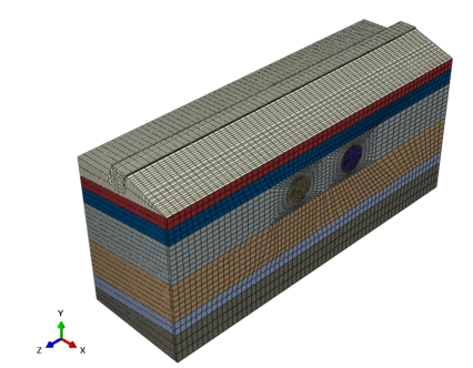
To better understand the real-world engineering scenario and design parameters, we have created a numerical calculation model using ABAQUS finite element software. This model aims to simulate the effects of the shield tunnel's construction. The tunnel consists of two parallel lines, with a centerline separation of 35m. We've represented the grouting filler within the shield tunnel gap as a uniform and equally thick grouting layer.
In our simulation, we've applied the thrust generated by the shield machine and the pressure exerted by cement in the form of nodal concentrated forces. Our model encompasses various elements, including the surrounding rock, pipe segments, grouting material, and the levees, all represented using solid elements.
The numerical model's dimensions are as follows: a longitudinal length of 56m, a transverse width of 180m, and a vertical height ranging from 76.1m to 84.6m. This extensive model is divided into 140,208 units and comprises 148,071 nodes, ensuring a comprehensive representation of the system. For a visual representation, please refer to Figure 6.
In our analysis, we employed the Mohr-Coulomb elastoplastic model for simulating soil behavior, while an elastic model was utilized for both the grouting layer and segment materials. The specific material parameters for these models are detailed in Table 2.
The boundary conditions and deformation constraints play a critical role in accurately representing the real-world scenario. At the top and surface of the levee, we have implemented free boundaries to allow for unrestricted movement. Around the levee, deformation constraints have been applied to capture the complex interactions. Additionally, at the bottom surface, we've limited deformation in the X, Y, and Z directions to reflect the ground's response. Furthermore, lateral constraints have been introduced on the sides of the model.
| Material name | weight(kN/m³) | cohesion(c)kPa | internal friction Angle φ(°) | Poisson's ratio υ | elastic modulus
E(MPa) |
| Sandy silt | 19.8 | 12 | 32 | 0.2 | 19 |
| silt | 19.9 | 13.5 | 33.4 | 0.22 | 20 |
| Silty clay | 17.6 | 19 | 32 | 0.25 | 8 |
| mucky clay | 18.4 | 27 | 34 | 0.35 | 4 |
| clay | 19.6 | 45 | 17.3 | 0.36 | 9 |
| Fully weathered rock | 22.3 | 50 | 22 | 0.26 | 320 |
| Moderately weathered rock | 22.6 | 200 | 22 | 0.23 | 550 |
| Grouting layer | 21 | / | / | 0.2 | 15 |
| segment | 25 | / | / | 0.17 | 34500 |
4.2 Simulation of shield excavation process
To simulate the step excavation process of the shield accurately, we utilize the element life and death function to manage the elements representing the shield machine, the grouting layer, and the segment. This process involves several key steps:
Initial Mud Support (N Analysis Step):In the N analysis step, we initiate the simulation by applying boundary conditions of mud pressure and pore pressure to the corresponding position of the palm surface, mimicking the mud support provided by the shield machine. This support pressure is continuously applied for one analysis step.
Soil Excavation (N+1 Analysis Step):In the N+1 analysis step, we replicate the excavation of soil as the shield machine advances. Here, we employ the life-death unit method to deactivate the soil elements in front of the original palm face. The shield unit in front of the machine is activated, while the shield unit in the rear is deactivated. We apply the same mud pressure and pore pressure conditions to the next palm face to simulate the shield's progress. Additionally, we activate the grouting layer and segment units at this position and apply radial grouting pressure and pore pressure boundary conditions to simulate the grouting process at the shield tail.
Grout Hardening and Dissipation (N+6 Analysis Step):In the N+6 analysis step, we conclude the process by closing the boundary conditions of grouting pressure and pore pressure at this position. Furthermore, we enhance the modulus of the isoplasmic layer material to model grout hardening and grouting pressure dissipation.
These steps are cyclically executed to achieve dynamic tunnel shield excavation.
4.3 Calculation results and analysis
4.3.1 Model verification
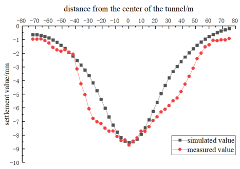
Figure 7 presents a comparison between the measured settlement curve and the calculated settlement curve of the embankment top following the shield tunneling through the levee. This visual representation allows us to assess the accuracy of our calculations and their compliance with specified requirements.As depicted in Figure 7, the maximum calculated settlement value at the top of the levee, after the left hole shield tunnel's completion, is 8.7mm. Importantly, this value meets the specified requirements outlined in the project specifications. Furthermore, it is worth noting that the calculated settlement curve closely aligns with the measured settlement curve, indicating a high level of accuracy in both our numerical calculation model and the associated processes outlined in this paper.
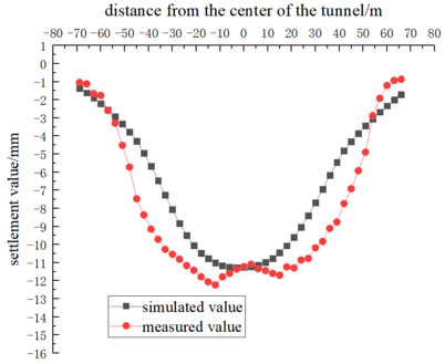
Figure 8 displays the calculated results of roof settlement in the levee during the penetration of the right-line shield. This visual representation allows us to assess the accuracy of our calculations and their compliance with project specifications.As depicted in the figure, the maximum measured settlement of the levee after the completion of the double-hole shield is 12.2mm. It's noteworthy that this value aligns with the specifications' requirements. While the calculated value is slightly smaller than the measured one, the agreement in the curve further substantiates the precision of our numerical calculation model.
4.3.2 Deep soil settlement of levee
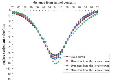
Figure 9 presents a comparative analysis of the lateral settling trough at the top of the levee and at depths of 10, 20, and 28 meters from the levee's top during the penetration of the left-line shield. Upon examining Figure 9, it becomes evident that the transverse settlement trough at varying depths of the levee exhibits a distinctive "V" shape, with the settling trough at the levee's summit showing a comparatively gentle slope. As we delve deeper, we observe a slight increase in soil settlement above the tunnel axis and a simultaneous reduction in the width of the settlement trough. This phenomenon can be attributed to the stress redistribution that occurs in the surrounding soil as the shield traverses the levee. This redistribution results in the formation of a lateral settlement trough. Notably, stress propagation at the top of the levee is more dispersed, leading to a less pronounced settlement effect. Moreover, with increasing depth, the soil above the tunnel axis gradually bears a greater load, contributing to a slight rise in settlement. The narrowing of the settlement trough width is a consequence of the localized nature of stress transfer.
The characteristics of deep soil settlement of the levee bear some resemblance to those induced by the φ6.34m subway shield [15]. However, it is noteworthy that the maximum soil settlement experienced by the levee and the extent to which the width of the sedimentation tank varies with depth are significantly less pronounced compared to the subway shield. In light of these observations, it is reasonable to consider that, under the specific conditions of this project, the width coefficient (ih) of the transverse sedimentation trough at varying depths closely approximates the width coefficient (i0) of the surface transverse sedimentation trough. When a large-diameter shield passes through the levee, the disparity between the settlement value at the levee's crest and the settlement value in the corresponding deep soil strata appears to be minimal. This suggests that, in practical engineering applications, the settlement value recorded at the levee's surface can effectively serve as an indirect indicator of deep soil settlement. Consequently, there may be no compelling need for the specialized arrangement of deep settlement monitoring points unless exceptionally high precision is warranted.
Figure 9. Lateral settlement curve of soil at different depths of levee
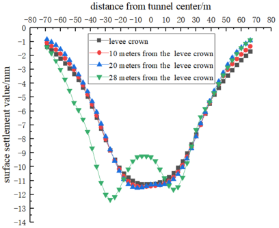
Figure 10 presents a comparison of transverse settling troughs at various depths when the right-line shield passes through the levee. This analysis aims to shed light on the settlement patterns during this process. Upon examination, it's evident that the maximum settlement during the penetration of the right-line shield increases by 3.5 meters compared to the single-hole scenario. As we delve deeper into the analysis, several trends emerge: (a) With increasing depth, soil settlement above the tunnel axis experiences a slight increase. (b) The width of the sedimentation tank shows a minor decrease with depth. (c) Settlement in the shield area, overall, follows a "W" shape distribution.
Notably, at a depth of 28 meters below the top of the embankment (coinciding with the grouting layer), there's a pronounced "W" shape settlement distribution. This phenomenon can be explained by two key factors:
1) The depth of 28 meters coincides with the shield construction area for the right-line, resulting in significant soil disturbance near the existing left line. This leads to soil redistribution and substantial settlement.
2) Additionally, this depth aligns with the grouting layer location. Typically, grouting processes enhance soil strength, potentially reducing interaction between soil masses. Consequently, the soil exhibits a marked "W" shape settlement distribution at the grouting layer depth.
In conclusion, this analysis reveals important settlement patterns during right-line shield penetration. These findings can have implications for future projects in similar conditions.
Figure 10. Lateral settling tank of soil in different depths of levee
4.3.3 Horizontal displacement of deep soil mass of levee
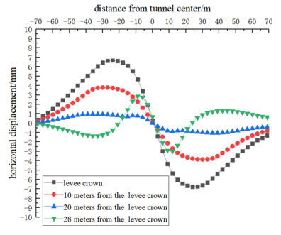
Figure 11 displays the horizontal displacement curves of the soil mass at the top of the levee and at depths of 10, 20, and 28 meters from the top when the left-line shield penetrates the levee. As seen from Figure 11, the horizontal displacement curve of the levee top exhibits an approximately inverted "S"-shaped distribution, symmetrically centered around the tunnel axis. The horizontal displacement directly above the axis is zero, while the horizontal displacement on both sides of the axis is non-zero and directed towards the tunnel axis. The maximum horizontal displacement is 6.6 millimeters, with symmetry appearing at positions ±i from the tunnel axis. There are distinct variations in the laws of change for soils at different depths:
1) At a depth of 10 meters from the top of the levee, the soil is situated in a shallower position, making it significantly affected by surface loads and shield construction. The mechanical compression from the shield and the lateral soil displacement result in substantial soil deformation, leading to a reduction in horizontal displacement. Consequently, the maximum horizontal displacement of the soil decreases by approximately 42.4% compared to the top position of the embankment.
2) As the depth increases to 20 meters, the soil is positioned deeper, and the influence of surface loads and construction decreases, resulting in minimal soil deformation. The reduction in horizontal displacement is also relatively modest, around 1 millimeter.
3) Concerning the depth of 28 meters from the top of the embankment, the soil is not only deep but also in proximity to the shield grouting layer. The maximum horizontal displacement occurs at positions ±0.5i, with a reverse bend point at the centerline of the tunnel. Despite minimal impact from surface loads, shield construction still induces significant deformation. The presence of the grouting layer likely enhances the soil's compressive strength, causing some soil to move towards the tunnel direction near the shield side and away from the grouting layer, resulting in an asymmetric displacement distribution.
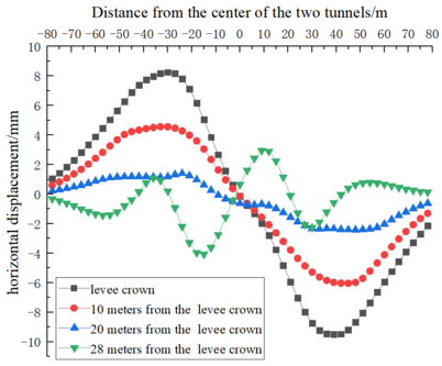
Figure 12 illustrates the horizontal displacement curves of the soil mass at the top of the levee and at depths of 10, 20, and 28 meters from the top after shield tunneling. As depicted in the figure, the horizontal displacement curve at the levee's crest exhibits an approximate "wave-like" distribution, symmetrically centered around the axis of the two tunnels. Above the axis, the horizontal displacement registers as zero, whereas on either side of the axis, the horizontal displacement is non-zero and directs toward the tunnel axis. The maximum horizontal displacement recorded is 9.2 millimeters, symmetrically distributed at positions ±i from the tunnel axis.
For soil at different depths, distinct patterns in the variation of horizontal displacement become apparent. At a depth of 10 meters from the levee's top, the soil, being in a shallower position, experiences significant influences from surface loads and shield construction. The mechanical compression from the shield and lateral soil displacement result in substantial soil deformation, leading to a reduction in maximum horizontal displacement of approximately 42.4% compared to the top position.
As depth increases to 20 meters, the soil is situated deeper, resulting in reduced influence from surface loads and construction activities. Consequently, soil deformation decreases, and the reduction in horizontal displacement is relatively modest, approximately 1 millimeter.
At a depth of 28 meters from the levee's top, coinciding with the position of the shield grouting layer, the soil displays a unique behavior. Maximum horizontal displacement is observed directly above the centerline of the tunnel. Additionally, there are inflection points in soil horizontal displacement at ±0.75i and ±i. Despite the minimal impact of surface loads, shield construction continues to induce significant soil deformation. The presence of the grouting layer appears to enhance the soil's compressive strength, causing some soil to move toward the tunnel and away from the grouting layer. This results in an asymmetric distribution of displacement.
To ensure the safety of the levee, real-time monitoring of horizontal displacement is imperative during the passage of a large-diameter shield tunnel, particularly for the deep soil layers within the levee. In cases where pile foundations or other retaining structures are present in the levee area, additional shear forces should be anticipated, necessitating proactive protective measures.
5. Conclusion
1. When the left line shield penetrates through the levee, the maximum settlement of the top reaches 8.7mm, which meets the deformation control requirements. The surface transverse settlement trough is distributed in a "V" shape, and the width of the sedimentation trough on the top of the levee is about 5 times of the width coefficient of the sedimentation trough. The settlement distribution can be estimated by the Peck formula. When the levee is passed under the right line, the maximum settlement of the top reaches 12.2mm, which has a wider influence on the soil and a larger settlement.
2. When the left line shield tunneling underpasses the levee, the lateral settlement at different depths of the levee is distributed in a "V" shape, and the lateral settlement trough at the top of the levee is relatively gentle. With the increase of depth, the soil settlement above the tunnel axis slightly increases, while the width of the settlement trough slightly decreases. When the right line shield underpasses the levee, the lateral settlement at different depths of the levee shows a "W" shape distribution, and the "W" shape settlement of the soil at the depth of the grouting layer is more significant.
3.The horizontal displacement curves of the top of the levee and deep soil mass (except the grouting layer) are approximately inverted "S" shape when the left line shield underpasses the levee and the right line shield underpasses the levee, and the maximum horizontal displacement of the top of the levee and deep soil mass (except the grouting layer) occurs at the position of ±i. And the maximum horizontal displacement of the right shield through the levee is greater than the maximum horizontal displacement of the left shield through the levee.
4.When the left line shield underpasses the levee, the maximum horizontal displacement at the grouting layer appears at the position of ±0.5i, and there is a reverse bending point at the center line of the tunnel. When the right line shield tunneling underpasses the levee, the maximum horizontal displacement at the grouting layer appears at the position of ±0.5i, and there are reverse bending points at the center line, ±0.75i and ±i of the tunnel.
Reference
[1] XIE Wenbin,WU Weiyi. Analysis of measured settlement of the Qiantang River embankment caused by under-crossing of large-diameter slurry shield tunneling[J]. Modern Tunneling Technology,2011,48(4):142-147.
[2] YANG Jiangang. Finite difference analysis of impact of undercrossing super-large-diameter shield tunnel on training jetty[J]. Chinese Journal of Geotechnical Engineering,2019,41(8):1569-1572.
[3] ZHANG Yazhou,XIA Pengju,ZHU Wei,et al. Analysis of stratum deformation and stability: a case study of the Nanjing Weisan road river-crossing tunnel passing under the Yangtze River embankment[J]. Modern Tunneling Technology,2015,52(4):151-157.
[4] HAN Lei,YE Guanlin,WANG Jianhua,et al. Finite element analysis of impact of under-crossing of large shallow shield tunnel on riverbank[J]. Chinese Journal of Geotechnical Engineering,2015,37(S1):125-128.
[5] LI Zongliang,HUANG Xigang. Study on settlement control for slurry shields crossing the embankment[J]. odern Tunneling Technology,2011,48(1):103-110.
[6] ZHANG Zhongmiao,LIN Cungang,WU Shiming,et al. Analysis and control of ground settlement of embankments in construction of cross-river shield tunnels[J]. Chinese Journal of Geotechnical Engineering,2011,33(6):977-984.
[7] Wu Weiyi, Sun Yukun, Li Liang et al. Analysis of levee deformation caused by large diameter shield tunneling in river Crossing Tunnel [J]. China Railway Science, 2016,37(04):78-82.
[8] Huang Hai. Research on settlement of Qiantang River levee caused by large-diameter shield construction [D] Zhejiang: Zhejiang University of Technology, 2018.
[9] ZHU Muyuan, Wei Lifeng, Fang Yong et al. Study on settlement analysis and control of large diameter shield tunnel under the Yellow River levee [J]. Modern Tunnel Technology. 2022,59(03):211-219.
[10] Xie Xiongyao, Yang Changzhi, Wang Qiang et al. Settlement analysis and control study of shield crossing levee of Yangtze River in Nanjing and Yanlu River Crossing Passage [J]. Chinese Journal of Rock Mechanics and Engineering. 201,40(S2):3313-3322.
[11] Lin Qibin,Cao Ping,Dong Tao. Numerical Simulation of Flood Control Levee Deformation by Shield Tunnel Excavation through the Liuyang River: A Case Study. GEOFLUIDS[J] Vol(2023):156-163.
[12] WU Shiming,LIN Cungang,ZHANG Zhongmiao,et al. Risk analysis and control for slurry shield under-passing embankment[J]. Chinese Journal of Rock Mechanics and Engineering,2011,30(5):1034-1042.
[13] PECK R B. Deep excavations and tunneling in soft ground[C]// State of the art report. Proceedings of 7th International Conference on Soil Mechanics and Foundation Engineering. Mexico City: 1969: 225-290.
[14] O’REILLY M P,NEW B M. Settlements above tunnels in the United Kingdom-their magnitude and prediction[C]// Proc. Tunnelling 82, Institution of Mining and Metallurgy, London: 173-182.
[15] Sun Yuyong,Zhou Shunhua,Gong Quanmei.Distribution of Deep Displacement Field during Shield Tunneling in Soft-soil Areas[J]. Chinese Journal of Rock Mechanics and Engineering,2009,28(3):500-506.
Document information
Published on 25/03/24
Accepted on 03/03/24
Submitted on 06/09/23
Volume 40, Issue 1, 2024
DOI: 10.23967/j.rimni.2024.03.003
Licence: CC BY-NC-SA license
Share this document
Keywords
claim authorship
Are you one of the authors of this document?

