(Tag: Visual edit) |
|||
| Line 95: | Line 95: | ||
The monitoring and early warning process is shown in Figure 5.Through the construction data, the theoretical maximum strain and maximum displacement of each rod of the construction support are calculated according to the theoretical maximum construction load, the monitoring scheme (monitoring points and instruments) is determined, the three-level warning value is set, and the actual data of the support during the construction process is monitored and collected throughout the day.Due to real-time monitoring, once there is a dangerous situation, the system could immediately give feedback to the construction site, adjust the construction, and then ensure construction safety, forming a closed-loop construction-monitoring chain. | The monitoring and early warning process is shown in Figure 5.Through the construction data, the theoretical maximum strain and maximum displacement of each rod of the construction support are calculated according to the theoretical maximum construction load, the monitoring scheme (monitoring points and instruments) is determined, the three-level warning value is set, and the actual data of the support during the construction process is monitored and collected throughout the day.Due to real-time monitoring, once there is a dangerous situation, the system could immediately give feedback to the construction site, adjust the construction, and then ensure construction safety, forming a closed-loop construction-monitoring chain. | ||
| − | + | [[File:Draft_房_828988194_5121_图片6.png]] | |
Fig.5 Monitoring and early warning flowchart | Fig.5 Monitoring and early warning flowchart | ||
Revision as of 12:25, 23 September 2022
1 Title, abstract and keywords
Construction Monitoring and Finite Element Simulation of Assembly Support for Large Cantilever Cover Beam
Abstract: The safety study is carried out for the large cantilevered cover beam assembly bracket used in the actual project, using real-time monitoring and early warning of the whole process, monitoring the strain and displacement development process of the bracket during the actual construction process, ensuring that the use of the bracket is in a safe state during the actual construction process while analysing the causes of its changes and proposing the timing of the bracket flow. Modelling of the support and numerical simulation for actual working conditions. The monitoring data and analysis results show that the overall bracket stress ratio is less than 30%, and after the concrete structure being supported hardens, the bracket is unloaded, and the bracket strain is reduced to less than 10% of the stress ratio before it is most appropriate to remove the bracket. The maximum strain does not exceed 66.26% of the theoretical maximum strain of the rod. The actual construction conditions and the spatial form of the bracket affect the force situation, resulting in a significant deviation from the theoretical maximum strain, and the analysis results and trends reflect the low utilisation rate of such bracket rods. The results of the study can be used as a reference for the topology optimisation of assembled bracing frames for large cantilevered cover beams.
Keywords: Large cantilever fabricated support; Real time monitoring and early warning; Simulation analysis; Stress ratio utility analysis
2 The main text
In the city's overpass system, it is common to see the existence of a large cantilever prestressed cover beam because of its overwhelming characteristics, such as long span, compact, small footprint, open to traffic and high urban utilisation rate. Both local and oversea scholars have in-depth study in the full load bearing bracket because of the extensive use and the comprehensive construction technique[1-6]. With the development of technology, society requires a shorter construction period, the traditional full load bearing bracket needs too much time and experienced workers to set up. Thus the large cantilever assembly support frame which cost less time and short turn over a period became a better choice to constructors, because of its passable stents, the construction process could minimise the influence on local traffic. Nowadays, the majority of researchers focus more on stents' construction technology or shape design, instead of force analysis. Although a part of researchers uses the finite element analysis method to simulate the loading condition of the heteromorphic stent, fewer of them apply the test in actual construction condition[7-11]. Moreover, internal and external scholars prefer to focus on stent monitoring and monitoring plan research rather than real-time construction process monitoring[12-16].
This essay is based on the Hangzhou Pengbu Interchange Reconstruction Project. It is focused on the real-time information monitoring of the first class large cantilever truss prestressed cover beam prefabricated support frame. The such stent is different from others. The superstructure is a cantilever truss structure which suitable for cantilever cover beam construction. Except for the shorter construction period, the primary advantage of it is the passable stent, which satisfies the requirements of traffic reconstruction on site. In order to generate a comprehensive monitoring plan, the high-frequency acquisition instrument is used to monitor the whole actual process of construction in real-time all day, simultaneously increasing construction security. Through data analysis and the change of force in the different construction phase, this essay is going to figure out the reliability rate and the optimal turning timing of stents. Furthermore, the finite element simulation and monitoring data will be compared and analysed to figure out the main factors that may affect the support force in the construction process. It provides technical support for safe construction and a basis for the broad application of this kind of stent.
1 project profile
The Hangzhou Pengbu Interchange reconstruction project is interworking in situ reconstruction. The total length of the road is around 1.73 meters. The main highway is 1.49m long. The bridge has a full width of 25.1m and a maximum span of 56m.The main line cover beam construction could be considered a risky project. The structure could be divided into three main types, which include: T-type, M-type, and F-type. Most of them are T-type structures, and 30 of them are the size of 25.11m×3.0m×2.4m. Because of the enormous traffic flow, the full of the support frame is not allowed to use here. However, the current construction does not use column. It means that except for the high cost and high-risk level, the force of the column in all directions is not uniform while constructing. Thus, the new large cantilever assembly bracket will be more suitable under such conditions. This essay mainly focuses on the monitoring and analysis of one of the support forms of the T-shaped cover beam.
This kind of support system mainly contains foundation, steel column, horizontal support, unloading sandbox, beam and scissors support. Steel components are mainly made of Q235 steel. The support rods are all standard H-shaped steel. The upper chord is 588×300 H-type steel, the lower chord is 440×300 H-type steel, the connecting rod is 250×250 H-type steel, and the vertical foundation supporting rod is 594×302 H-type steel. For more information, the foundation is connected to the column by anchor bolts of embedded parts, the middle column is connected to the C30 concrete foundation and embedded parts of the cap platform by anchor bolts, and the unloading sandbox is set between the steel column and the beam for force transmission and unloading. The specific structure of the support is shown in Figure 1.
Fig.1 Support structure2 Construction monitoring and actual data analysis
2.1 Construction monitoring and forewarning
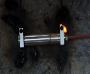
During this strain monitoring test, the monitoring position is decided by the structure position classification and the theoretical stress of the rod.The strain monitoring was performed using JDEBJ vibrating chord surface strain gauge, which was uploaded to the monitoring cloud by HC-M610/4/8 wireless data acquisition instrument.
The network monitoring platform is shown in Figure 3.
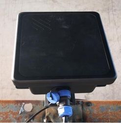
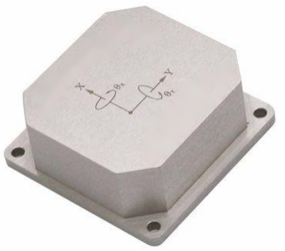
It allows 24 hours data collection without interruption to ensure the implementation of construction monitoring data transmission, and it provides timely strain situation to ensure the real-time safety of the support construction. Moreover, the IICC-NDM non-contact disturbance detector was used for displacement monitoring, and HC-B300 Double-axis digital inclinometer was used for bracket tilt.
(a)IICC-NDM Non-Contact Flexure Tester (b)HC-B300 Double-axis digital inclinometer (c)JDEBJ vibrating chord surface
Fig.2 Monitoring instruments
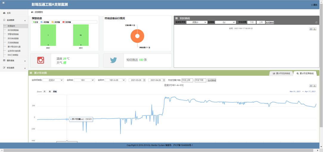 Fig.3 Network monitoring platform
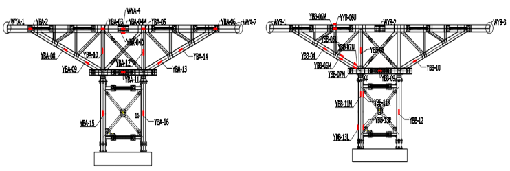
The specific monitoring position is shown in Figure 4.There are 30 strain monitoring stations (some of the monitoring test bar are stress form correctly, and the i-steel web and flange set two strain gauge respectively); 6 displacement monitoring point (using three deflection detector by fixed position instrument, the relative position between the monitoring and measurement instrument, determine stent displacement deformation, displacement of each instrument can be used to detect two points); and one inclination monitoring point (placed on the central column)
Fig. 4 Layout of monitoring positions of product A and product B supports
The monitoring and early warning process is shown in Figure 5.Through the construction data, the theoretical maximum strain and maximum displacement of each rod of the construction support are calculated according to the theoretical maximum construction load, the monitoring scheme (monitoring points and instruments) is determined, the three-level warning value is set, and the actual data of the support during the construction process is monitored and collected throughout the day.Due to real-time monitoring, once there is a dangerous situation, the system could immediately give feedback to the construction site, adjust the construction, and then ensure construction safety, forming a closed-loop construction-monitoring chain.
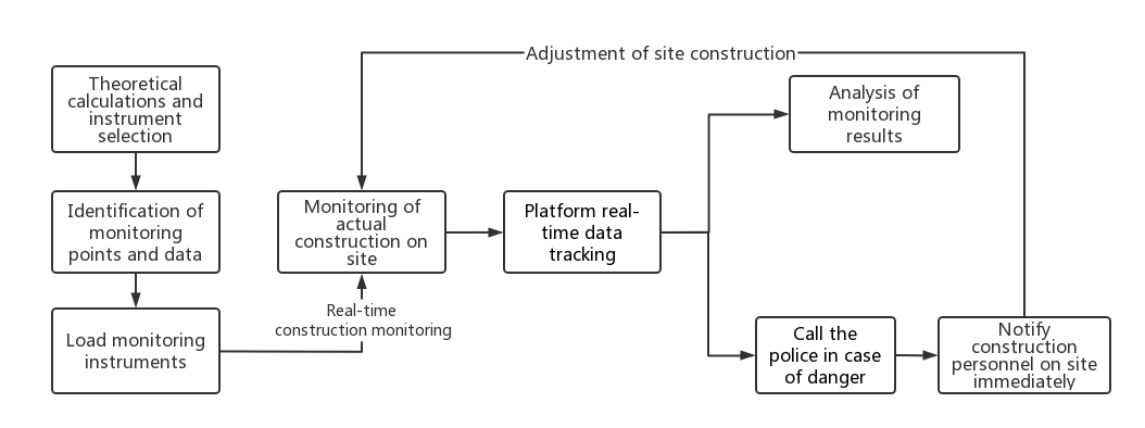 Fig.5 Monitoring and early warning flowchart
During the construction period, in order to provide early warning for the actual construction, according to the design cover beam construction load (construction load 5 KN/m2, formwork load 2 KN/m2, concrete load 26 KN/m2), it was considered that the brackets should all be warned within the yield load, so the theoretical maximum strain situation of the brackets was calculated for all bars according to the elastic bars (after the action of the upper beryl beam of the brackets, so the maximum theoretical load was divided according to The maximum strain on the bracket caused by the uniform distribution of the load on the two independent brackets) and the theoretical maximum displacement resulting from the larger displacements are calculated. After taking into account the material yield strength of each rod in comparison with the instability strength of the space structure, each strength meets the requirements, so a three-stage warning is proposed in accordance with 110%, 120% and 130% of the theoretical maximum strain to guide the construction on site.
Table 1 Early warning values of strain at each measuring point (strain unit: με)
| Number | Level 1 | Level 2 | Level 3 | Number | Level 1 | Level 2 | Level 3 |
| YBA-03 | 915 | 998 | 1043 | YBB-04 | 550 | 600 | 651 |
| YBA-04D | 768 | 845 | 922 | YBB-05U | 723 | 789 | 855 |
| YBA-04M | 768 | 845 | 922 | YBB-05M | 723 | 789 | 855 |
| YBA-05 | 915 | 998 | 1043 | YBB-06U | 915 | 998 | 1043 |
| YBA-08 | 550 | 600 | 651 | YBB-06M | 915 | 998 | 1043 |
| YBA-09 | 723 | 789 | 855 | YBB-11R | 351 | 383 | 414 |
| YBA-10 | 273 | 298 | 322 | YBB-11M | 351 | 383 | 414 |
| YBA-11 | 620 | 676 | 732 | YBB-07U | 723 | 789 | 855 |
| YBA-13 | 723 | 789 | 855 | YBB-07M | 723 | 789 | 855 |
| YBA-14 | 550 | 600 | 651 | YBB-08 | 273 | 298 | 322 |
| YBA-12 | 273 | 298 | 322 | YBB-09 | 620 | 676 | 732 |
| YBA-16 | 351 | 383 | 414 | YBB-10 | 723 | 789 | 855 |
| YBA-15 | 351 | 383 | 414 | YBB-12 | 351 | 383 | 414 |
| YBA-02 | 239 | 261 | 283 | YBB-13R | 351 | 383 | 414 |
| YBA-06 | 239 | 261 | 283 | YBB-13L | 351 | 383 | 414 |
3 References
Document information
Published on 12/01/23
Accepted on 26/12/22
Submitted on 24/09/22
Volume 39, Issue 1, 2023
DOI: 10.23967/j.rimni.2023.01.001
Licence: CC BY-NC-SA license
Share this document
claim authorship
Are you one of the authors of this document?

