The modeling of both synchronous generator and induction motor which is represented by the rotor reference frame was studied where the modeling was established using MATLAB /SIMULINK software package for an isolated synchronous generator direct-on-line with different sized induction motors; 20, 50, and 100 Hp, at manually adjusted excitation voltage values which were maintained constant at 3.35, 4.55, and 6.21 V, respectively. The purpose of this work is to study the impact of a sudden increase in the load torque; from 0 to 150 % with an increase of 25 %, full load torque was studied at a constant motor speed of 188.49 rad sec-1. On the other hand, the impact of a sudden decrease in the rotor speed by about 20 % from its rated value; from 188.49 to 150.79 rad sec-1 was also studied at full load torque of the same different sized induction motors. These values were manually recorded and response variables of the generator including terminal voltage, current, output power, electromagnetic torque, and load angle were determined and represented as a function of time. The results illustrated the Changes in the terminal voltage, the current, the output power, the electromagnetic torque, and the load angle as parameters of a synchronous generator for different sized induction motors.
Keywords: Dynamic model, Matlab /Simulink, Synchronous generator
1. Introduction
The induction motors are the most energy-consuming loads especially in isolated grids, such as emergency generation plants, which are used for industrial power loads, shopping centers, hospitals, conveyors, fans, eand lectric energy systems of ships. The induction motors, especially the squirrel-cage type, are the most common machines used in various industrial applications owing to their simple design, rugged structure, high accuracy, great self-starting ability, good efficiency, and low maintenance requirements.
The direct-on-line starting is the simplest method used for starting the squirrel-cage induction motor in isolated electrical networks. Generally, a normal value of starting current is between 6 to 7 folds the rated current which could reach in large size induction motors to up to 9 or 10 folds, will cause supply voltage dips and torque disturbance were suggested according to [1,2].
There are many parameters that affect the performance of the synchronous generator such as the sudden changes in each mechanical input power, excitation voltages, load torque, and also the nature of load type. These changes cause that the performance of the synchronous generto paspasses by a transient period until reaching the steady-state operative conditions. The various loads of synchronous generators were discussed by several authors but till now, there is no study related to the sudden changes in both mechanical speed and the load [3-8].
Thus, the aim of this work was to study the impact of a sudden increase in the load torque at constant rotor speed as well as the sudden decrease in the rotor speed at full load torque for different sized induction motors on the behavior of the synchronous generator with a constant voltage of excitation. The response variables include the terminal voltage, current, torque, output power, load angle, and speed where these responses are represented as a function of time.
Materials and methods
The dynamic model of synchronous generator
The synchronous generator applied in this work is composed of uniform three armature windings that are sinusoidally distributed along the air gap, with only one field winding. Additionally, Damper windings existed in the rotor; where one of them is found along the direct-axis; d-axis, and the other one along the quadrature-axis (Q) with 90 electrical degrees behind the d-axis.
The field winding was put on the d-axis where the modeling of the damper circuit was performed throughout a short-circuited winding along the direct and quadrature axis representing the impact of induced currents within the damper bars and further in the rotor body, where the positive rotation direction was opposite to that of clockwise. The positive angle θ was then determined from the axis of phase-A to the d-axis. Based on this, some hypothesizes were suggested according to [8] in order to improve the dynamic model of the synchronous generator as shown below:
- Representing the flux linkages as a function of the rotor place,
- Magnetically connected all the windings,
- Neglecting both copper losses and the slots in the synchronous generator, and
- The permeability of both stator and rotor is infinite,
The windings of phases A, B, and C are exemplified with the inductances La, Lb, and Lc (self and mutual inductance). Due to the magnetic connections between the stator and the rotor parts, as well as the flux linking of the windings are both dependent on rotor position. The electrical equations were derived using Kirchhoff’s voltage law to each winding, in other words, by equalization of the voltage at the terminal of the winding with the sum of all voltages drop (resistive and inductive) across the winding. In addition, if damper windings are present, they are always short-circuited, and their terminal voltage is always zero. As a result, the equations of the dynamic voltage of the synchronous generator were within the rotor reference frame [8, 9] as follows:
.... (1)
……………...... (2)
…………………………....……............... (3)v
0
=
−
r
s
.
i
0
+
d
ψ
o
d
t
{\textstyle {v} {0}=-{r} {s}.{i} {0}+{\frac {d{\psi } {o}}{dt}}}
…………………………....……............... (3)
……… (4)
…... (5)
………….. (6)
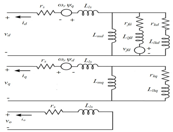
Where these mathematical equations represent the synchronous generator equivalent circuit in the rotor reference frame as illustrated in Fig. (1).
Fig. 1 Equivalent circuit of a three-phase synchronous machine in the rotor reference frame
The dynamic model of induction motor
The stator of the induction motor is made up of three-phase windings where each of which is separated from the other two by 120 degrees in space and a three-phase rotating magnetic field is created when the current runs throughout these windings. While the squirrel cage type is composed of a number of bars which in turn form a number of symmetrical loops where each is made up of two rotor bars that are joined by two end ring parts. Owing to the coupling between the stator and rotor windings along with the variation of coupling coefficient with the rotor position, studying the operative performance of the machine is therefore very complicated. As a result, the dynamic model of the induction motor was described by some differential equations with the time-varying coefficients. Therefore, a few assumptions should be applied when the mathematical dynamic model used for a 3-phase squirrel cage induction motor [10-12 and 15] as follows:
- Stator windings are designed and arranged in such a way that they can produce sinusoidal MMF distributions along air gap;
- Mutual inductances are equal value;
- The harmonics in the voltages and the currents are ignored;
- The effects of each saturation, eddy currents, and hysteresis are ignored;
- Uniform air gap;
- The iron parts permeability is unlimited.
To simplify the differential equations that describe the induction motor, the two-axis theory is therefore applied where the performance behavior of the induction motor is described by the time- varying voltage and torque equations.
Voltage equations
Stator circuit
Provided the equations of stator voltage for a three-phase induction motor according to [10-13] as follows:
..…….. (7)
Rotor circuit
Provided the following equations for the rotor voltage according to [11-15]:
…..…….. (8)
Where, are the magnetic flux linkage of phases a, b, and c.
Flux linkage equations
The stator and rotor mutual inductances, also the line currents were used to develop the flux linkage equations between them where the flux linkages were provided by [11-15] as shown below:
|
|
(9) |
Where: ias, ibs, ics are the stator windings currents, iar, ibr ,icr are the rotor windings currents and the inductances are described below.
Inductances equations
Stator inductances
The main components of the self-inductance of the stator windings are magnetizing and leakage inductance. As the windings are symmetrical, the self-inductance of all stator windings is thus equal, as given by the following relationships [11-14]:
…………. (10)
Where Lls: is the stator leakage inductance which identical for all phases and Lms: is the stator magnetizing inductance.
Because of consistency of the stator windings, the mutual inductance of any two stator windings is equal.
……………………… (11)
Where, Lms is the magnetizing inductance of the stator windings.
Rotor inductances
As with the stator, the rotor self-inductance is equal as shown by the following relations presented by [11-14]:
………… (12)
Where Llr: is the rotor leakage inductance which symmetrical for all phases and Lmr is the rotor magnetizing inductance.
The mutual inductances are then calculated as follows:
………………….. (13)
Where Lmr is the magnetizing inductance of the rotor
Mutual inductances between stator and rotor windings
It was observed that the mutual inductance between a stator winding and any rotor winding changes sinusoidally with the rotor position according to [11-14] as follows:
…… (14)
Where θr: is rotor angle, Lmsr: is the mutual inductance between a rotor and stator winding when the rotor angle is such that the rotor and the stator magnetic axes are aligned, and the subscripts indicate which rotor and stator windings defining e mutual inductance between them. As a result, the derivatives of such these inductances related to the time are havplicitly existed in the machine equations where the three-phase squirrel-cage induction motors in the rotating DQ axis were described as follows according to [12]:
……………………… (15)
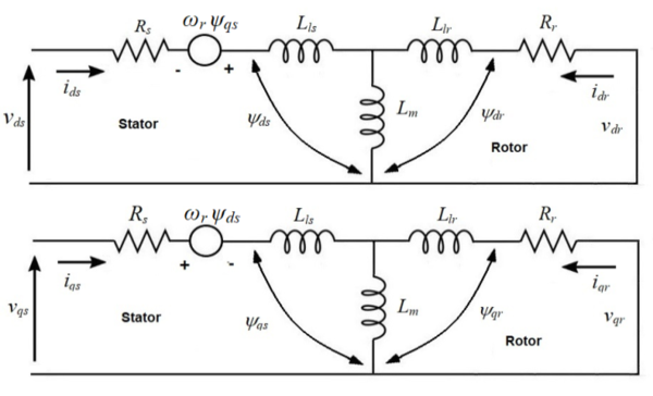
Therefore, figure (2) illustrates the equivalent circuits of a 3-phase squirrel cage induction motor by the rotor reference frame with ignored zero sequence components according to [10] as follows:
………………………… (16)
…. (17)
Fig. 2 The induction motor equivalent circuit in the rotor reference frame
'3.' The dynamic model of synchronous generator D.O.L induction motor
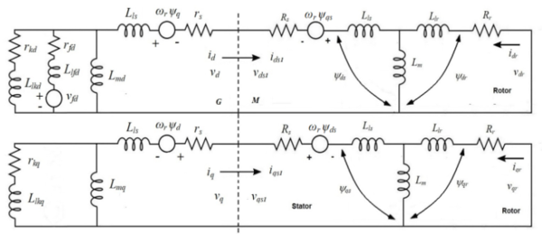
Figure (3) illustrates the equivalent circuit of the isolated synchronous generator direct online by the squirrel cage induction motor by the rotor reference frame. In addition, the equation (18) represents all equations of stator voltage, and current of the synchronous generator D.O.L by induction motor in the rotating DQ axis, indicating that they are on the same voltage and current.
…………………………………… (18)
Fig. 3 Equivalent Circuit of an isolated synchronous generator D.O.L induction motor in rotor reference frame
Results and discussion
Matlab/simulink model
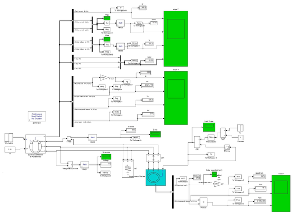
Figure (4) illustrates the performed dynamic modeling of an isolated synchronous generator direct on-line by induction motor using MATLAB /SIMULINK software package where the synchronous generator was loaded with different sized induction motors loads (20, 50, and 100 Hp). In manual mode, the excitation voltage is set with the required values of 3.36, 4.64, and 6.21 V, respectively to maintain the generator’s terminal voltage equal to the estimated value of 460 V at full load. Subsequently, the simulated values of each terminal voltage, current, output power, torque, load angle, and speed as a function of time were determined. The performance of the synchronous generator with a constant excitation voltage is affected by several operative parameters like the sudden increase in the load torque at a constant rotor speed of 188.49 rad sec-1 and the sudden decrease in rotor speed at full load torque. The specifications of the synchronous generator and the differen- sized induction motors used in this work exist in the Appendix.
Fig. 4 MATLAB / SIMULINK model of an isolated Synchronous Generator D.O.L Starting Induction Motor load
Effect of the sudden increase in the load torque at constant the rotor speed
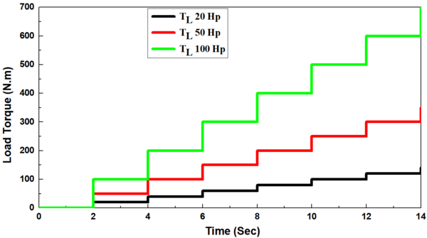
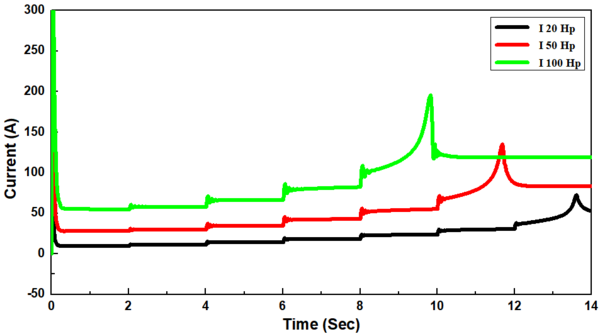
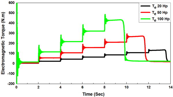
With different sized induction motors (20, 50, and 100 Hp), the synchronous generator was firstly connected direct-on-line with induction motor without load torque (TL=0) in the period (0-2 s) and the load torque was then suddenly applied in a step form in the periods 2-4, 4-6, 6-8, 8-10, 10-12, and 12-14 s, where the load torque ranged from 25% to 150 % of full load torque with a gradual increase of 25 %, respectively, Figure 5(a). The values of starting currents were obtained to be 163.35, 470.4, and 989 A, respectively for different sized induction motors of 20, 50, and 100 Hp, which increased by about 6 - 9 folds of full load current, and in some cases, it could attain 10 folds. The current drawn by induthe ction motor in the period of 0-2 s which was just after starting the period with no-load (TL=0) is known as the no-load current which represents about 40-50 % of full load currents of 9.72, 27.65, and 54.78 A, respectively.
Moreover, it was found that when these loads were applied during the mentioned periods, the current drawn (withdrawn) by the induction motor gradual increased, and it reaches to the full load current of 27.6 and 54.7 A, respectively for induction motors with sizes of 20 and 50 Hp at full load torque in the period 8-10 s. on the other hand, it was also observed that the current drawn by induction motor with sizthe e of 100 Hp did not meet the full load current as in Fig. 5(b). While, it increased greatly versus the dip in voltage in a 5 and 100 Hp- induction motors, as in Fig. 5(b).
Also, the field current instantaneously increased when the load torque increased, and it return to maintain constant value at 99.06 and 134.35 A, respectively for induction motors with sizes of 20, 50 and100 Hp at full load torque in the period 8-10 s this because the excitation system employed is a battery with a constant voltage. While, it increased as similar to stator current greatly versus the dip in voltage in a , and 100 Hp- induction motors, as in Fig. 5(c).
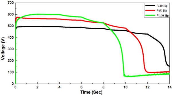
The voltage at the generator terminals declined with each increase in the load torque until the voltage-dip. The voltage dip occurred after loading by 125, 100, and 75 % of full load torque for induction motors with sizes of 20, 50, and 100 Hp, respectively. The voltage dip is due to the load torque becoming greater than the generation torque, and there is no procedure (voltage regulator) to bring the terminal voltage back to the setpoint by increasing the field.as in Fig. 5(d).
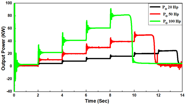
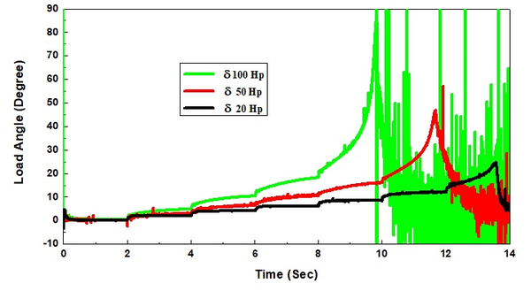
Moreover, the power drawn by the induction motor increased provisionally after the no-load period reaching thereafter a steady state condition for each increase in the load applied on the induction motor as mentioned above where it approaches almost zero after the voltage-dip, Fig. 5(e). There is a direct relation between the electrical torque and the output power and an inverse relation between the electrical torque and rotor speed where . As a result, the torque increased temporally reaching thereafter a stable condition with each increment in the load applied on the induction motor with a similar trend of output power. It is due to the constant speed and approaching near zero after voltage dip, Fig. 5(f). In addition, the load angle increased with an increase in the load torque, but it increased instantaneously and then decreased thereafter when the voltage-dip occurring, Fig. 5(g).
Fig. 5 Impact of a sudden increase in the load torque at a constant rotor speed on an isolated synchronous generator D.O.L by different sizing induction motors (20, 50, 100 Hp) at constant the rotor speed (a) Load torque, (b) Stator Current, (c) Field Current (d) Voltage, (e) Output Power, (f) Torque and (g) Load Angle.
Effect of the sudden decrease in the rotor speed
It was found that decreased mechanical input power results in a smaller turbine torque passed to the synchronous generator decreasing the rotor speed. Figure (6) illustrates the impact of the sudden decrease in rotor speed from 188.49 rad/sec to 150.72 rad sec-1 in the period of 2-4 s on the behavior of an isolated synchronous generator direct-on-line by different sized induction motors of 20, 50, and 100 Hp at full load torque.
The current drawn by the induction motor declined when the rotor speed decreased from 22.89, 53.66, and 103.95 A to 22.5, 53.09, and 105.4 A respectively, reaching thereafter a stable condition in the two sized induction motors of 20, 50 Hp. While, it increased greatly versus the dip in voltage in a 100 Hp- induction motor, as in Fig. 6(a). Also, the field current decreased slightly when the rotor speed decreased from 99.37, 137.72, and 197.51 A to 98.95, 136.39, and 195.76 A respectively reaching thereafter a stable condition in the two sized induction motors of 20, 50 Hp, this, because the excitation system employed, is a battery with a constant voltage. While, it increased as similar to stator current greatly versus the dip in voltage in a 100 Hp- induction motor, as in Fig. 6(b).
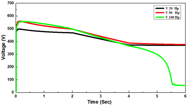
Furthermore, it was found that the generator terminal voltages declined when the rotor speed decreased from 467.7, 496.9, 498.8V to 372.4, 387.6, 366.09 V, respectively, reaching thereafter a stable condition in two sized induction motors of 20 and 50 Hp. While, the voltage-dip occurred in a 100 Hp- induction motor, as in Fig. 6(c). The voltage dip is due to the decrease in the rotor speed as a result of decreasing the fuel amount which in turn decreases the generating torque, and also this model there is no contains (voltage regulator) to bring the terminal voltage back to the setpoint by increasing the field.
Manually, the excitation voltage was adjusted to (3.36, 4.64, and 6.21 V), respectively to keep the flux of field constant. As a result, the internal generated voltage EA= Køw decreased. Therefore, a decrease in output power was observed with a decrease in the terminal voltage where , it declined from 16.19, 39.05, 78.83 Kw to 12.59, 30.45, and 59.47 Kw, rWspectively reaching thereafter a stable condition in two siz-d induction motors of 20 and 50 Hp. while in a 100 Hp- induction motor, the output power approached almost zero after occurring the voltage-dip as Fig. 6(d).
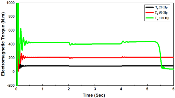
Due to the direct relationship between the electrical torque and the output power and the inverse relation between the electrical torque and the rotor speed (Tem=Pout/ωs), it declined as rotor speed was decreased from 86.12, 211.5, and 428.17 Nm to 84.18, 204.9, and 406.67 Nm respectively reaching thereafter a stable condition in two sized induction motors of 20, 50 Hp. But in a 100 Hp- induction motor, the torque approached almost zero after occurring the voltage-dip, as Fig. 6(e).
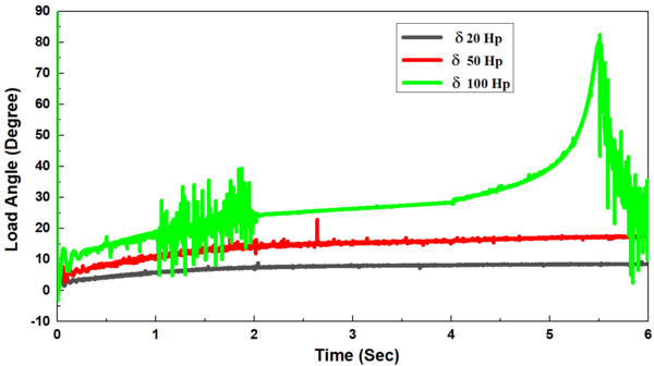
Conversely, as the rotor speed decreased, the load angle (δ) increased from 7.6, 14.48, and 24.73 ° to 8.18, 15.95, and 28.34° where , reaching thereafter a stable condition in two sized induction motors of 20, 50 Hp. However, it increased greatly versus the dip in the voltage in the 100 Hp- induction motor, as Fig. 6(f).
Fig. 6 Effect of the sudden change in the rotor speed on an isolated synchronous generator D.O.L by different sizing induction motors (20, 50, 100 Hp) at full load torque on (a) Stator Current, (b) Field Current (c) Voltage, (d) Output Power, (e) Torque, and (f) Load Angle.
Conclusion
In this study, the mathematical dynamic model of the synchronous generator direct-on-line by an induction motor is analyzed in the case e of rota or reference frame. The modeling of an isolated synchronous generator direct-on-line by different sizes induction motors (20, 50, 100 Hp) was performed using MATLAB /SIMULINK software package with constant and adjusted the excitation voltage at (3.35, 4.55 an,d 6.21V), respectively. The generator parameters were experimentally measured and the generator simulated values (terminal voltage, current, output power, electromagnetic torque, and load angle as function of time) were subsequently calculated.
The obtained results show that the current, the output power, the electromagnetic torque, and the load angle increased with increasing the load torque at a constant speed. While the terminal voltage decreased with increasing then load torque at a constant speed. In the case of a sudden decrease in the rotor speed at full load torque, only the load angle increased. In this study, the voltage dip may be due to
1) The load torque was greater than the generation torque,
2) The decrease in the rotor speed as a result of decreasing the fuel amount which in turn decreases the generating torque.
Appendix
The specifications of the synchronous generator as well as the induction motors applied in the simulation were as follows:
Synchronous generator specifications
The synchronous generator applied in this work was 100 KVA, 460 V, 125.5-A, 60 Hz, 4 pole 3-phase cylindrical pole synchronous generator, star-connected
Per phase stator resistance (Rs): 0.055 Ω
Per phase stator reactance (Xs): 21.6317 Ω
Resistance of the field windings Rf = 0.03386 Ω
The generator moment of inertia J = 0.7136 kg.m2
The generator's friction factor B = 0.06 N-ms
Rated rotor Speed =1800 r.p.m.
Induction motor 1 specifications
Three-phase squirrel cage Υconnected, 20 HP, 460-V, 23.4 -A, 60 Hz, 4 poles
Speed (N):1760 rpm
Per phase stator resistance (R1): 0.2761Ω
Per phase stator reactance (X1):0.82598 Ω
Referred rotor per phase resistance (R2): 0.1645 Ω
Referred rotor per phase reactance (X2): 0.82598 Ω
Magnetizing inductance (Xm): 28.704 Ω
Moment of inertia (J): 0.1 kg m2
Friction factor (F): 0.01771 N m s
Induction motor 2 specifications
Three-phase squirrel cage Υconnected, 50 HP, 460-V, 52-A, 60 Hz, 4 poles
Speed (N):1780 rpm
Per phase stator resistance (R1): 0.09961 Ω
Per phase stator reactance (X1): 0.32685 Ω
Referred rotor per phase resistance (R2): 0.05837 Ω
Referred rotor per phase reactance (X2): 0.32685 Ω
Magnetizing inductance (Xm): 11.4567Ω
Moment of inertia (J): 0.4 kg m2
Friction factor (F): 0.02187 N m s
Induction motor 3 specifications
Three-phase squirrel cage Υ-connected, 100 HP, 460-V, 117-A, 60 Hz, 4 poles
Speed (N): 1780 rpm
Per phase stator resistance (R1): 0.03957 Ω
Per phase stator reactance (X1): 0.146649 Ω
Referred rotor per phase resistance (R2): 0.02215 Ω
Referred rotor per phase reactance (X2): 0.146649 Ω
Magnetizing inductance (Xm): 6.2731322 Ω
Moment of inertia (J):1.3 kg m2
Friction factor (F):0.05543 N m s
Acknowledgment
I thank to Prof. Dr. Fathy Abd-el-Kader (At Electrical Engineering Department, Faculty of Engineering, Menofeya University, Egypt) and Dr. Mohamed Abdel Fattah Enany (At Electrical Powers & Machines Department, Faculty of Engineering, Zagazig University, Egypt) for their technical suggestion and full guidance towards completion of this paper.
- [1] B. T., Jaykishan R., Jay D., and Kamlesh S., “Soft Start of Induction Motor Using TRIAC Switching”, International Journal of Engineering Development and Research (IJEDR), Vol. 5(2), pp. 1635-1639, 2017. www.ijedr.org
- [2] Mahmoud M.S. A., “Development of the system of preemptive control over excitation of a synchronous generator to reduce voltage dips when starting-up asynchronous motors”, Przegląd elektrotechniczny, R. 94, NR 10, pp. 210- 215, 2018. doi:10.15199/48.2018.10.49
- [3] Guogang W., Shiyu S., and Jinning L., “Influence of Motor Starting on The Operating Characteristics of Diesel Generator Sets”, Advances in Computer Science Research, Vol. 71
- [4] Marija M., and Zlatko M., “Torsional Dynamics of Generator Units During Sudden Impact Load”, Electrical and Electronic Engineering, Vol. 2(4), pp.183-191, 2012. doi: 10.5923/j.eee.20120204.03
- [5] Marija M., Zlatko M., and Daniel P., “The Dynamics of Diesel-Generator Unit in Isolated Electrical Network”, International journal of renewable Energy Research, IJRER, Vol. 1(3), pp.126-133, 2011. doi: 10.5923/j.eee.20120204.03
- [6] Marija M., Zlatko M., and Ivan G., “Effects of Interruption in Power Supply of Induction Motors in Isolated Electrical Grid”, Acemp - Electromotion, pp.732-735, 2011.
- [7] M. MiroSevid, Z. Maljkovid, and M. MilkoviC, “Dynamics of Generator-Units During the Start-up of the Induction Motor Drives”, IEEE Melecon, pp.1109-1112, 2004
- [8] Nashwa M., Mohamed E., and Fathy E., “Dynamic operation of isolated self-excited synchronous generator under static loads”, Journal of Electrical Systems, Vol. 17(3), pp. 310-323, 2021. www.journal.esrgroups.org/jes/
- [9] E. J. Akpama, K. M. Udoka, and O. I. Okoro., “Dynamic Modeling of Induction Machine Incorporating Transmission Line Impedance”, International Journal of Recent Development in Engineering and Technology, Vol. 7(6), pp. 7-13, 2018. www.ijrdet.com
- [10] Pema D. and Bevek S, “D-Q Mathematical Modelling and Simulation of Three-Phase Induction Motor for Electrical Fault Analysis”, International Advanced Research Journal in Science, Engineering and Technology, Vol. 7(9), pp. 38-46, 2020. http://doi: 10.17148/IARJSET.2020.7909
- [11] Pratyusha B. D. and Sudhangshu S., “Dynamic Model Analysis of Three Phase Induction Motor Using Matlab/Simulink”, International Journal of Scientific & Engineering Research, 7(3), pp. 572-577, 2016. http://www.ijser.org.
- [12] Onofre A. M., Carlos E. C., Riemann R. C., Fredy A. V. Miguel A. M., Abel E. Q., and Nahitt P., “The Squirrel-Cage Induction Motor Model and Its Parameter Identification Via Steady and Dynamic Tests”, Electric Power Components and Systems, Vol. 0(0), pp. 1-14, 2018. https://doi.org/10.1080/15325008.2018.1445140
https://www.tandfonline.com/loi/uemp20
- [13] Sang-H. K., “Electric Motor Control DC, AC, and BLDC Motors”, Published by Elsevier Inc. 2017. http://dx.doi.org/10.1016/B978-0-12-812138-2.00004-0
- [14] Reuben J., Onah C. O., and J. U. Agber, “Modeling and Simulation of Three Phase Induction Motor Electrical Faults Using Matlab/Simulink”, International Journal of Modern Trends in Engineering and Research (IJMTER), Vol. 5(5), pp. 176-187, 2018.
http://doi.10.21884/ijmter.2018.5158.zxudq
- [15] Martin. K., Anastázia M., and Michal K., “Modeling of Synchronous Machines Including Voltage Regulation”, Przegląd Elektrotechniczny, R. 95 NR 7, pp. 125-132, 2019. http://doi:10.15199/48.2019.07.26
| NASHWA M. MOUNIR (Non-member) received a Bachelor of Science degree in Electrical Power and Machines Engineering – at Zagazig University in 2002, Masters of Science degree in Electrical Power and Machines Engineering- at Zagazig University, in 2010. She is currently a design and implementation engineer at the Housing Directorate - Sharkia Governorate- Egypt. Her research interests include electrical machines. E-mail: nashwamounir@yahoo.com, |
| MOHAMED A. ENANY (Non-member) was born in January 1979. He received the B.Sc., M.Sc., and Ph.D. degrees in electrical power and machines engineering from the Engineering College, Zagazig University, Egypt, in 2000, 2005, and 2009, respectively. He is currently an Associate Professor in power and electrical machines engineering with the Engineering College, Zagazig University. He has many international publications in the areas of electrical machines, renewable energy, soft computing techniques, and electrical drives.
E-mail: m_enany79@yahoo.com
|
| FATHY EL-SAYED (Non-member) received a Bachelor of Science degree in Electrical Power Engineering - at Mansoura University in 1970, a Masters of Science degree in power and electrical machines - at Helwan University in 1977, and a Doctor of Philosophy degree in power and electrical machines - Mansoura University, in 1979. He is currently a Professor in electrical power and machines engineering with the Engineering College at Minufiya University. His research interests include electrical machines.
E-mail: fatkader2@yahoo.com |
Document information
Accepted on 19/08/22
Submitted on 12/08/22
Licence: CC BY-NC-SA license
Share this document
Keywords
claim authorship
Are you one of the authors of this document?
