Abstract
The paper presents an overview of the advances in recent years on the finite element method (FEM) and on particle-based methods for the simulation of industrial metal forming processes. More specifically, we present the evolution of the FEM in the field from the early plastic/viscoplastic flow approaches to the new stabilized FEM for analysis of multiphysics bulk forming processes. Also the paper describes the state of the art in the new rotation-free shell elements for simulation of sheet stamping processes. Finally, we present the so-called Particle Finite Element Method (PFEM), as a component of a family of new computational techniques integrating particle-based methods and mesh-based procedures. The PFEM is particularly suited for large deformation problems in solids and fluids involving nonlinear mechanical and geometrical effects, fluid-structure interactions and frictional contact situations. Applications of the FEM and the PFEM to several metal and material forming processes are presented.
Keywords: Finite element method, Particle-base Methods, Particle Finite Element Method, PFEM, Metal forming
The Flow Formulation
The first applications of the FEM in the industrial forming field go back to the early 1970´s. Most FEM developments in the field at that time were based on standard rigid-plastic theory [Pittman et al. (1984)]. In those days Zienkiewicz et al. introduced the so called “flow formulation” allowing to follow up with the FEM the large deformation of rigid-plastic/viscoplastic solids during bulk forming operations [Zienkiewicz (1984), Zienkiewicz et al. (1978)]. The method basically exploits the analogy between the equations of an incompressible rigid-plastic/viscoplastic solid and those of a non-Newtonian Stokes fluid. The flow analogy establishes that the velocities, strain rates, stresses and viscosity in the non Newtonian fluid can be interchanged with the displacements, strains, stresses and the shear modulus in the equivalent incompressible elastic solid. The resulting system of equations in the FEM can be thus seen as the solution of a non linear incompressible elasticity problem in which the shear modulus is a non linear function of the strain and stress levels. The flow approach was successfully applied in conjunction with the FEM for the analysis of many bulk forming problems (rolling, extrusion, forging, etc) [Pittman et al. (1984), Zienkiewicz (1984), Zienkiewicz et al. (1978)].
Extensions of the flow approach and the FEM to account with thermal-coupling effects in hot forming processes were presented in [Zienkiewicz et al. (1981), Kobayashi (1984)]. The flow analogy was also applied to sheet metal forming problems via the so called viscous shell formulation. A particular feature of viscous shell elements is that incompressibility in the metal sheet during deformation is satisfied by a simple updating of the sheet thickness, taking advantage of the plane stress assumption of shell theory [Oñate and Zienkiewicz (1983), Oñate and Agelet (1990)].
The flow approach was soon extended to incorporate elastic effects. Different FEM formulations based on non linear continuum mechanics theory were reported in the period 1980-1995. The basic differences here are the constitutive model chosen and the use of displacements or velocities as the main nodal variables. Many applications of the elastoplastic/viscoplastic flow approach to bulk and sheet metal forming processes using the FEM have been reported in Zienkiewicz et al. (2005), Rojek et al. (1998). Extensions of the FEM to account with adaptive mesh refinement procedures for bulk forming analysis can be found in Zienkiewicz et al. (1988).
Stabilized FEM for Multiphisics Bulk Forming Problems
The application of the FEM to bulk forming problems expanded rapidly to problems of multiphysics nature were coupled interactions between fluids and solids appear. Two characteristic problems of this kind are the analysis of polymer moulding and casting processes. The possibility to couple the simulation of the mould filling operation with the subsequent solidification and cooling of the melt become a reality by the mid 1990´s. The solution typically requires using stabilized FEM for modelling the turbulent flow of the melt in the mould during the filling, as well as for analysis of the deformation of the part and the mould during the solidification and cooling phases accounting for thermal-mechanical coupling effects and frictional contact conditions [Celentano et al. (1994,1996), Codina et al. (1994), Agelet et al. (1999), Cervera et al. (1999), Agelet et al. (2001)].
Application to aluminium casting simulation
A numerical simulation of an aluminium casting process is presented as a demonstration of the accuracy of the stabilized formulation. The computations are performed with the finite element code VULCAN where a stabilized FEM has been implemented [VULCAN (2011)].
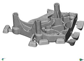
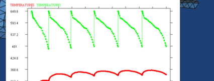
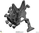
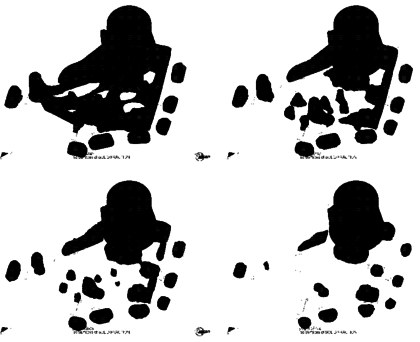
The analysis simulates the casting process of an aluminium (AlSi7Mg) specimen in a steel (X40CrMoV5) mould. Material behavior of aluminium casting has been modeled by a fully coupled thermo-viscoplastic model, while the steel mould has been modeled by a simpler thermo-elastic model [Oñate et al. (2006)]. Fig. 1 shows the finite element mesh used for the part and the cooling system. The full mesh, including the mould has 380.000 four node tetrahedra. The pouring temperature is 650oC. Initial temperature for the mould is obtained through a thermal die-cycling simulation. Fig. 2 shows the evolution of the mould temperature after 6 cycles. The cooling system has been kept at 20oC. Filling evolution has been simulated as in a pressure die-casting process using a stabilized FEM/VOF technique [Codina et al. (1994)]. Fig. 3 shows different time steps of the simulation.
The final temperature field obtained after the filling simulation is taken as the initial condition for the solidification and cooling analysis. The temperature distribution during solidification is shown in Fig. 4.
Forming of a hose-clamp band
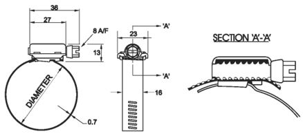
The stabilized FEM was applied to model the manufacturing of a hose-clamp band of AISI 409L steel (Fig. 5). The initial set-up of the tooling and band is shown in Fig. 6. A series of grooves are forged in the band by the roll passing over the band placed on the toothed punch. The band thickness is 0.7 mm and its width 8 mm. Plane strain conditions are assumed. Material properties can be found in Oñate et al. (2006).
Simulation was carried out using stabilized linear triangular elements. The finite element mesh was regenerated when element distorsion was excessive. The purpose of the simulation was to check if the expected groove depth and tooth height in the band were obtained. Fig. 7 shows the deformed shapes and the distribution of the effective plastic strain at different stages of forming. The results are in good agreement with values obtained in the real process.
Figure 7. Hose clamp. Deformed shapes at different stages of forming with distribution of effective plastic strain.
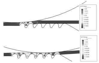
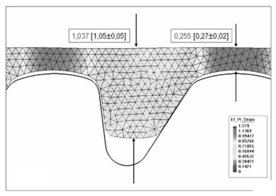
Figure 8. Hose-clamp. Detail of the deformed shape with finite element discretization and effective plastic strain distribution.
Fig. 8 shows a detail of the deformed shape with finite element discretization and the distribution of effective plastic strain. The obtained dimensions are compared with the required ones shown in brackets. Effects of elastic springback can be clearly seen.
FEM for Sheet Metal Forming Processes
In the field of sheet metal forming the FEM evolved from using the simple 3-noded triangle based on membrane theory in the early 1970´s, to the development and application of sophisticated shell elements rooted in the principles of non linear shell theory in recent years. The two numerical schools in the field basically differ from using either an implicit or an explicit (dynamic) solution approach. The former allows larger time steps (or load increments) for the transient (or quasi-static) solution. The explicit dynamic scheme, on the other hand, is simpler to implement and facilitates the treatment of frictional contact conditions which are a challenging problem in sheet stamping analysis. The drawback of the explicit method is the limitation in the maximum time step size for numerical stability, which results in very small time increments for thin metal sheets. The debate between using implicit or explicit methods for metal forming simulations is still open in the computational mechanics community and different codes based on one or other procedure are available in practice.
Among the recent advances of the FEM in the sheet metal forming field, we note the development of the so-called rotation-free shell elements [Oñate and Zárate (2000)]. The name refers here to the formulation of shell elements using the displacements as the only nodal degrees of freedom. Rotation-free shell elements are typically of triangular shape [Oñate and Zárate (2000), Oñate and Flores (2005), Oñate et al. (2007), Gärdsback and Tibert (2007)], although quadrilaterals are also possible [Flores and Estrada (2007)]. The simpler rotation-free shell triangle has three nodes and three displacement variables per node. The curvature field is computed using information from the nodal displacements of the patch of elements formed by a central triangle and the three adjacent triangles. A rotation-free shell triangle of this kind, termed BST for Basic Shell Triangle, was developed by Oñate and Zárate (2000) and later enhanced in Oñate et al. (2007) (the so called EBST1 element). Applications of rotation-free shell triangles to sheet metal forming problems using explicit and implicit solution schemes are reported in Oñate and Flores (2005), Oñate et al. (2007).
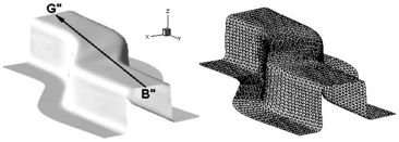
Figure 9. Stamping of a S-rail. Final deformation of the sheet after springback obtained in the simulation. The triangular element mesh of the deformed sheet is shown.
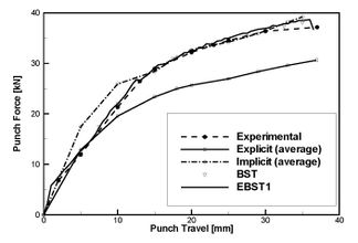
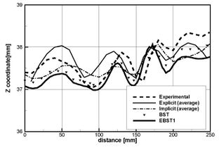
Figure 10. Stamping of a S-rail. (a) Punch force versus punch travel. (b) Z-coordinate along line B´´-G´´ after springback. Average of explicit and implicit results reported in NUMISHEET'96 (1996) are also shown.
S-rail Sheet Stamping
The analysis comprised two parts, namely, simulation of the stamping of a S-rail sheet component and springback computations once the stamping tools are removed. Numerical results were obtained with the sheet stamping code STAMPACK [STAMPACK (2011)]. Fig. 9 shows the deformed sheet after springback.
The detailed geometry, material properties and FEM data can be found in Oñate et al. (2006), NUMISHEET'96 (1996). The mesh used for the sheet has 6000 EBST1 elements and 3111 nodes (Fig. 9). The tools are treated as rigid bodies. Fig. 10a compares the punch force during the stamping stage obtained with BST and EBST1 elements and the experimental values. The average values of the simulations reported in NUMISHEET'96 (1996) are shown. Explicit and implicit simulations are considered as different curves. There is a remarkable coincidence between the experimental values [NUMISHEET'96 (1996)] and the results obtained with both the BST and the enhanced EBST1 elements. Fig. 10b plots the Z coordinate along line B"-G" after springback. The top surface of the sheet does not remain plane due to some instability due to the low blank holder force used. Simulations results compare very well with experimental values.
Stamping of Industrial Automotive Part
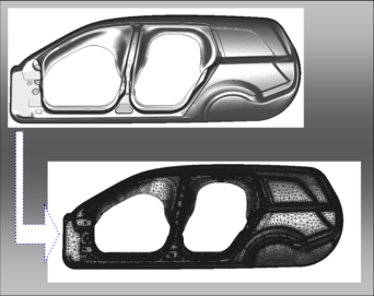
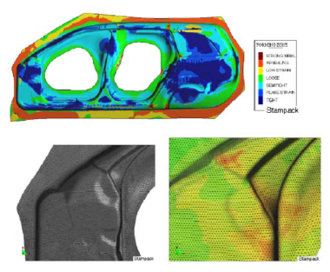
Fig. 11 shows the geometry of the lateral panel of a car and the mesh of 457760 EBST1 elements used for the computation. Results of the stamping simulation using STAMPACK [STAMPACK (2011)] are shown in Fig. 12. The outputs of the simulation have been translated into graphical plots indicating the quality of the stamping process and the risk of failure in the different zones of the panel. This helps designers for taking decisions on the adequacy of the stamping process and for introducing changes on the design of the stamping tools (dies, punch, blankholders, etc.) and on the process parameters if needed.
Figure 11. Lateral panel of an automotive. Finite element mesh of 457760 EBST1 triangles used for the simulation.
The Particle Finite Element method
We finally mention the potential of the new Particle Finite Element Method (PFEM, www.cimne.com/pfem). The PFEM integrates an innovative particle-based technique with the FEM to solve complex multiphysics problems in fluid and solid mechanics [Oñate et al. (2004), Oñate et al. (2010)]. In the PFEM nodes are considered as lagrangian particles which move under external or internal forces. A mesh connects the nodes at each time step defining the computational domain where the equations of continuum mechanics are solved with the standard FEM. The PFEM has a big potential for the analysis of bulk forming processes involving very large deformations of deformable continua (both fluids and solids), fluid-structure-thermal interactions and multiple frictional contact conditions .Initial applications of the PFEM in the industrial forming field are reported in Oñate et al. (2006), Cante et al. (2004).
Filling of moulds
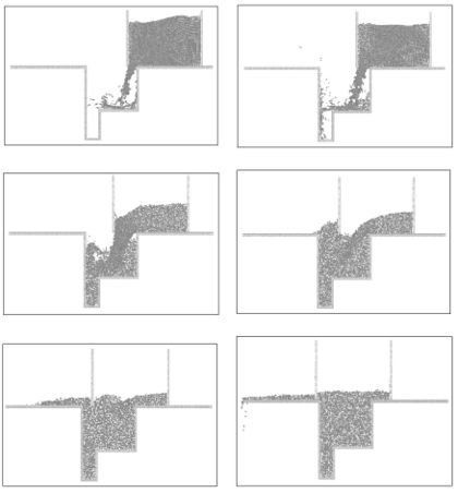
Fig. 13 shows the results of the filling of a 2D mould cavity with a powder material using the PFEM. The essential feature of the filling process are well reproduced. The mesh used for the computation at a certain instant is shown in Fig. 13b. This ilustrates the fact that the PFEM is, in fact, a blending of particle and finite element procedures. Other applications of the PFEM to powder compaction problems are reported in Oñate et al. (2006), Cante et al. (2004).
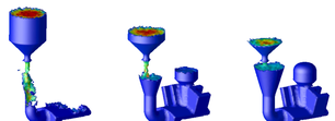
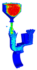
Fig. 14 shows the simulation of the casting of a mechanical part using the PFEM. The mesh discretizing the casted region is progressively generated as the mould is filled. This is a distinct feature of the PFEM which distinguishes this method from VOF techniques using Eulerian and ALE approaches.
Mixing problems
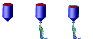
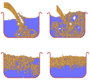
Fig. 15 shows an example of application of the PFEM to the mixing of a collection of particles within a container filled with a fluid of a higher density. Initially the particles are thrown into the container and mix within the fluid as shown. As time evolves the particles move up towards the surface of the fluid due to their lower density.
This example clearly shows the possibilities of the PFEM for analysis of material mixing situations. Applications of the PFEM in this field can be found in Idelsohn et al. (2009).
Conclusions
We have presented an overview of the advances on the finite element method (FEM) and on the new particle-finite element method (PFEM) for industrial metal forming processes. The new stabilized FEM offer many possibilities for analysis of multiphysics bulk forming processes. Also the new rotation-free shell elements are a powerful technique for simulation of sheet metal stamping processes. The PFEM is particularly suited for simulation of bulk metal forming problems involving coupled fluid-structure interaction, material non linearity and complex frictional contact situations.
(a)
Figure 13. (a) Filling of a 2D mould with a powder material using PFEM. (b) Mesh used at a certain instant. Circles indicate external and internal free surfaces.
Acknowledgements
The company Quantech ATZ SA (www.quantech.es) kindly provided the casting code VULCAN and the sheet stamping code STAMPACK for the simulations presented in the paper. PFEM results were obtained with the PFLOW code developed at CIMNE (www.cimne.com). This support is gratefully acknowledged.
References
Agelet de Saracibar, C., M. Cervera, M. Chiumenti, 1999. On the Formulation of coupled thermoplastic problems with phase-change. Int. J. of Plasticity 15, p. 1-34.
Agelet de Saracibar, C., M. Cervera, M. Chiumenti, 2001. On the constitutive modeling of coupled thermo-mechanical phase-change problems. International Journal of Plasticity 17, p. 1565-1622.
Cante, J.C., J. Oliver and C. González, 2004. Powder forming simulation with the particle finite element method. Computational Mechanics, Z.H. Yao, M.W. Yuan and W.X. Zhong (Eds.), CD-Rom Proceedings of the WCCM VI, Beijing, September 5-10.
Celentano, E., E. Oñate, S. Oller, 1994. A temperature-based formulation for finite element analysis of generalized phase-change problems. Int. J. Num. Meth. Engng. 37 (20), p. 3441-3465.
Codina, R., U. Schaefer, E. Oñate, 1994. Mould filling simulation using finite elements. Int. J. Num. Meth. Engng. 4, p. 291-310.
Celentano, D., S. Oller, E. Oñate, 1996. A coupled thermomechanical model for the solidification of cast metals. Int. J. of Solids and Structures 33 (5), p. 647-673.
Cervera, M., C. Agelet de Saracibar and M. Chiumenti, 1999. Thermo-mechanical analysis of industrial solidification processes. Int. J. Num. Meth. Engng. 46, p. 1575-1591.
Flores, F.G., Estrada, C.F., 2007. A rotation-free thin shell quadrilateral. Comput Meth Appl Mech Engng. 196, p. 2631-2646.
Gärdsback, M., Tibert G., 2007. A comparison of rotation-free triangular shell elements for unstructured mesh. Comput Meth Appl Mech Engng. 196, p. 5001-5015.
Kobayashi, S., 1984. Thermoviscoplastic analysis of metal forming problems by the finite element method. In J.F.T. Pittman et al. (eds.), Numerical Analysis of Forming Processes, Chap. 2, p. 45-70. Wiley, Chichester.
Idelsohn S., Mier-Torrecilla M., E. Oñate, 2009. Multi-fluid flows with the PFEM. Comput Meth Appl Mech Engng. 198 (33-36), p. 2750-2767.
NUMISHEET'96. Third Int. Conf. on Numerical Simulation of 3D Sheet Forming Processes. Lee EH, Kinzel GL, Wagoner RH (eds), Dearbon-Michigan, USA, 1996.
Oñate, E., O.C. Zienkiewicz, 1983. A viscous shell formulation for the analysis of thin sheet metal forming. Int. J. Mech. Sci. 25, p. 305-335.
Oñate, E., C. Agelet, 1990. Finite element analysis of sheet metal forming problems using a selective bending membrane formulation. Int. J. Num. Meth. Engng. 30, p. 1577-1593.
Oñate, E., F. Zárate, 2000. Rotation-free plate and shell triangles. Int J Num Meth Engng. 47, p. 557-603.
Oñate, E., S.R. Idelsohn, F. Del Pin and R. Aubry, 2004. The Particle finite element method. An overview. Int. J. Comput. Meth. 1 (2), 267-307.
Oñate, E., F.G. Flores, 2005. Advances in the formulation of the rotation-free basic shell triangle. Comput Meth Appl Mech Engng. 194 (21-24), p. 2406-2443.
Oñate, E., J. Rojek, M. Chiumenti, S.R. Idelsohn. F. Del Pin, R. Aubry, 2006. Advances in stabilized finite element and particle methods for bulk forming. Comput Meth Appl Mech Engng. 195 (48-49), p. 6750-6777.
Oñate, E., F.G. Flores, L. Neamtu, 2007. Enhanced rotation-free basic shell triangle. Applications to sheet metal forming. E. Oñate and R. Owen (eds.), Computational Plasticity, Springer, The Netherlands, p. 239-265.
Oñate, E., R. Rossi, S. Idelsohn, K. Butler, 2010. Melting and spread of polymers in fire with the PFEM. Int. J. Numerical Methods in Engineering 81 (8), 1046-1072.
Pittman, J.F.T., Zienkiewicz, O.C., Wood, R.D. and Alexander, J.M. (eds.), 1984. Numerical Analysis of Forming Processes, Wiley, Chichester.
Rojek, J., E. Oñate, E. Postek, 1998. Application of explicit FE codes to simulation of sheet and bulk metal forming processes. J. Mat. Proc. Tech. 80-81, p. 620-627.
STAMPACK. A finite element code for simulation of sheet metal forming processes. www.quantech.es, 2011.
VULCAN. A finite element code for simulation of casting and founding processes. www.quantech.es, 2011.
Zienkiewicz O.C., P.C. Jain and E. Oñate, 1978. Flow of solids during forming and extrusion: some aspects of numerical solutions. Int. J. Solids Struct. 14, p. 15-38.
Zienkiewicz O.C., E. Oñate and J.C. Heinrich, 1981. A general formulation for coupled thermal flow of metals using finite elements. Int. J. Num. Meth. Engng. 17, p. 1497-1514.
Zienkiewicz O.C., 1984. Flow formulation for numerical solutions of forming problems. In J.F.T. Pittman et al. (eds.), Numerical Analysis of Forming Processes, Chapter 1, p. 1-44. Wiley, Chichester.
Zienkiewicz, O.C., Y.C. Liu, G.C. Huang, 1988. An error estimate and adaptive refinement method for extrusion and other forming problems. Int. J. Num. Meth. Engng. 25, p. 23-42.
Zienkiewicz, O.C., R.L. Taylor, P. Nithiarasu, 2005. The Finite Element Method for Fluid Dynamics. Vol. 3, Chap. 5, 6ª Edition, Elsevier Butterworth-Heinemann.
Document information
Published on 01/01/2011
Licence: CC BY-NC-SA license
Share this document
Keywords
claim authorship
Are you one of the authors of this document?
